EP1083814B1 - Wiping material dispensing drum in dispensing apparatus with format and length adjustment of the dispensed material - Google Patents
Wiping material dispensing drum in dispensing apparatus with format and length adjustment of the dispensed material Download PDFInfo
- Publication number
- EP1083814B1 EP1083814B1 EP99911876A EP99911876A EP1083814B1 EP 1083814 B1 EP1083814 B1 EP 1083814B1 EP 99911876 A EP99911876 A EP 99911876A EP 99911876 A EP99911876 A EP 99911876A EP 1083814 B1 EP1083814 B1 EP 1083814B1
- Authority
- EP
- European Patent Office
- Prior art keywords
- drum
- cylinder
- format
- hub
- ring
- Prior art date
- Legal status (The legal status is an assumption and is not a legal conclusion. Google has not performed a legal analysis and makes no representation as to the accuracy of the status listed.)
- Expired - Lifetime
Links
- 239000000463 material Substances 0.000 title claims abstract description 24
- 230000005489 elastic deformation Effects 0.000 claims abstract description 8
- 238000005520 cutting process Methods 0.000 claims description 12
- 230000002093 peripheral effect Effects 0.000 claims description 3
- 230000001681 protective effect Effects 0.000 claims description 3
- 238000003825 pressing Methods 0.000 claims description 2
- 238000009826 distribution Methods 0.000 description 8
- 241001417494 Sciaenidae Species 0.000 description 4
- 230000000694 effects Effects 0.000 description 4
- 230000000903 blocking effect Effects 0.000 description 2
- 239000000470 constituent Substances 0.000 description 2
- 238000003892 spreading Methods 0.000 description 2
- 229920002678 cellulose Polymers 0.000 description 1
- 239000001913 cellulose Substances 0.000 description 1
- 230000000295 complement effect Effects 0.000 description 1
- 230000008878 coupling Effects 0.000 description 1
- 238000010168 coupling process Methods 0.000 description 1
- 238000005859 coupling reaction Methods 0.000 description 1
- 238000006073 displacement reaction Methods 0.000 description 1
- 238000007373 indentation Methods 0.000 description 1
- 238000004519 manufacturing process Methods 0.000 description 1
- 230000035515 penetration Effects 0.000 description 1
Images


Classifications
-
- A—HUMAN NECESSITIES
- A47—FURNITURE; DOMESTIC ARTICLES OR APPLIANCES; COFFEE MILLS; SPICE MILLS; SUCTION CLEANERS IN GENERAL
- A47K—SANITARY EQUIPMENT NOT OTHERWISE PROVIDED FOR; TOILET ACCESSORIES
- A47K10/00—Body-drying implements; Toilet paper; Holders therefor
- A47K10/24—Towel dispensers, e.g. for piled-up or folded textile towels; Toilet-paper dispensers; Dispensers for piled-up or folded textile towels provided or not with devices for taking-up soiled towels as far as not mechanically driven
- A47K10/32—Dispensers for paper towels or toilet-paper
- A47K10/34—Dispensers for paper towels or toilet-paper dispensing from a web, e.g. with mechanical dispensing means
- A47K10/36—Dispensers for paper towels or toilet-paper dispensing from a web, e.g. with mechanical dispensing means with mechanical dispensing, roll switching or cutting devices
- A47K10/3631—The cutting devices being driven manually
- A47K10/3643—The cutting devices being driven manually by pulling the paper
-
- A—HUMAN NECESSITIES
- A47—FURNITURE; DOMESTIC ARTICLES OR APPLIANCES; COFFEE MILLS; SPICE MILLS; SUCTION CLEANERS IN GENERAL
- A47K—SANITARY EQUIPMENT NOT OTHERWISE PROVIDED FOR; TOILET ACCESSORIES
- A47K10/00—Body-drying implements; Toilet paper; Holders therefor
- A47K10/24—Towel dispensers, e.g. for piled-up or folded textile towels; Toilet-paper dispensers; Dispensers for piled-up or folded textile towels provided or not with devices for taking-up soiled towels as far as not mechanically driven
- A47K10/32—Dispensers for paper towels or toilet-paper
- A47K10/34—Dispensers for paper towels or toilet-paper dispensing from a web, e.g. with mechanical dispensing means
- A47K10/36—Dispensers for paper towels or toilet-paper dispensing from a web, e.g. with mechanical dispensing means with mechanical dispensing, roll switching or cutting devices
- A47K10/3631—The cutting devices being driven manually
- A47K2010/365—Triggering mechanism for the blade
-
- Y—GENERAL TAGGING OF NEW TECHNOLOGICAL DEVELOPMENTS; GENERAL TAGGING OF CROSS-SECTIONAL TECHNOLOGIES SPANNING OVER SEVERAL SECTIONS OF THE IPC; TECHNICAL SUBJECTS COVERED BY FORMER USPC CROSS-REFERENCE ART COLLECTIONS [XRACs] AND DIGESTS
- Y10—TECHNICAL SUBJECTS COVERED BY FORMER USPC
- Y10T—TECHNICAL SUBJECTS COVERED BY FORMER US CLASSIFICATION
- Y10T83/00—Cutting
- Y10T83/465—Cutting motion of tool has component in direction of moving work
- Y10T83/4766—Orbital motion of cutting blade
- Y10T83/4795—Rotary tool
- Y10T83/4812—Compound movement of tool during tool cycle
-
- Y—GENERAL TAGGING OF NEW TECHNOLOGICAL DEVELOPMENTS; GENERAL TAGGING OF CROSS-SECTIONAL TECHNOLOGIES SPANNING OVER SEVERAL SECTIONS OF THE IPC; TECHNICAL SUBJECTS COVERED BY FORMER USPC CROSS-REFERENCE ART COLLECTIONS [XRACs] AND DIGESTS
- Y10—TECHNICAL SUBJECTS COVERED BY FORMER USPC
- Y10T—TECHNICAL SUBJECTS COVERED BY FORMER US CLASSIFICATION
- Y10T83/00—Cutting
- Y10T83/647—With means to convey work relative to tool station
- Y10T83/654—With work-constraining means on work conveyor [i.e., "work-carrier"]
-
- Y—GENERAL TAGGING OF NEW TECHNOLOGICAL DEVELOPMENTS; GENERAL TAGGING OF CROSS-SECTIONAL TECHNOLOGIES SPANNING OVER SEVERAL SECTIONS OF THE IPC; TECHNICAL SUBJECTS COVERED BY FORMER USPC CROSS-REFERENCE ART COLLECTIONS [XRACs] AND DIGESTS
- Y10—TECHNICAL SUBJECTS COVERED BY FORMER USPC
- Y10T—TECHNICAL SUBJECTS COVERED BY FORMER US CLASSIFICATION
- Y10T83/00—Cutting
- Y10T83/889—Tool with either work holder or means to hold work supply
- Y10T83/896—Rotatable wound package supply
Definitions
- the invention relates to the technical sector of distribution devices for wiping paper in cellulose wadding, crepe paper, or similar material, intended more particularly for wiping the hands of users, for distribution of toilet paper, distribution of paper towels. These papers can be folded or unfolded.
- the aim sought after according to the invention was therefore to design a new drum for distributing the wiping material capable of allowing strip distribution cut material of varying length in a simplified configuration and More reliable.
- the material distribution drum wiping in a dispenser with adjustment of format and length of the material delivered the apparatus being of the type comprising a casing (2), a cover (3), a drum (10), a cutting device (5) integrated in the drum arranged longitudinally in a slot fitted to the latter, characterized in that the drum (10) comprises a hub (11) defining in its central part a crown (11e) serving as a point of attachment and adjustment in position of the cylinder part (16) of the drum, according to variable positions by defining a variation of the format of the length strip of the material, and in that the cylinder part (16) of the drum is made in two parts likely to have a spreading movement relative to each other by elastic deformation of one of the parts of the cylinder in order to define the drum circumference and variation in format, said parts being lockable in position relative to each other.
- the drum (10) comprises a hub (11) defining in its central part a crown (11e) serving as a point of attachment and adjustment in position of the cylinder part (16) of the drum, according to variable positions
- the device is referenced as a whole by (1) and comprises a casing (2), a cover (3), a drum, a cutting device (5) integrated in the drum, as well as means for launching and recalling the drum including an eccentric (7) and a spring (8).
- the casing is arranged with flanges (2a) capable of receiving the reel holder (9) of a reel wiping material (B).
- a pressing element (6) can be arranged to rest on the drum between which the paper passes origin of the coil.
- the device does not include elements presser and the reel paper strip is in direct support on the drum when it is pulled for cutting.
- the drum is represented as a whole by (10). he first comprises a hub (11) made in two parts (11a - 11b) having at one end a disc plate (11c - 11d) which are juxtaposed one against the other to form a crown constituting the support base and fixing of a profiled part capable of constituting the peripheral periphery of the cylinder (16) of the drum.
- the other ends (11f) of the parts (11a - 11b) of the hub are susceptible to be engaged and secured on forms in sleeves (12 - 13) secured to end flanges (14 - 15) capable of receiving the device section (5).
- the flange (14) associated with the sleeve (12) has an axial extension to from which the eccentric (7) is shaped with finger (7a) for fixing the drum return and start spring.
- the second flange (15) is arranged to allow in particular the attachment of the blade holder of the chopped off.
- the cylinder part (16) of the drum and surrounding the hub is capable of mate on the crown (11e) thus established in a configuration particular ensuring, according to positions, a variation of the circumference of the drum and therefore by defining a variation of the format of the length of the strip of cut material.
- said cylinder (16) is in practice made in two parts which are likely to have a spreading movement relative to the other in order to define the circumference of the drum and the variation thereof.
- the cylinder (16) comprises two first parts identical arranged on either side of the crown (11e) of the hub and includes a sleeve (16a).
- the latter includes a ring portion (16a1) arranged opposite and adjacent to the crown extended radially and towards the interior with legs (16a2).
- the disc plates (11c-11d) defining the hub crowns are also arranged with oblong slots curvilinear (11g).
- the aforementioned legs (16a2) are arranged opposite said lights, and connecting and fixing means (17) ensure their coupling.
- These means (17) include in particular an axis (17a) which is capable of moving in said lights as a function of movements spacing between the first and second parts of the cylinder.
- said rings of small width are established on approximately an angle of 150 to 180 °. They extend by a curvilinear bearing surface (16a3) defining a complementary support part of the cylinder for the strip of pulled paper.
- This litter is very long substantially to the end flanges of the end of the drum carried by the hub.
- This seat (16a3) is semi-cylindrical with slots (16a4), up to end near the longitudinal exit zone of the cutting device outside the drum. Said slots established over part of the length of the spans provide flexibility allowing elastic deformation of the first part of the cylinder.
- the ring of the first part of the cylinder is arranged near its free end with a plurality of cutouts (16a5 - 16a6) established on the one hand at the end, and on the other hand along its border external device, and whose interest will appear later.
- the first part of the cylinder (16) is susceptible a certain elastic deformation by spacing and extension in particular in the area of the ring thus established.
- This second cylinder part is established in the form of plates (18) articulated with respect to the hub crown.
- the latter presents and on the other side of its plane projecting cylindrical spans (19) on which are mounted rings (18a) associated with each plate (18).
- These plates are likely to come into underlying support and partially on the part ring of the first part of the cylinder.
- Each plate (18) has a curvilinear profile configuration with an interior area (18b) in overlap of the aforementioned ring part and an adjacent zone (18c) raised likely to be in the same plane as the part of the cylinder in the state rest.
- said zone (18c) and the outer surface of the ring of the first cylinder part are arranged with a rough surface likely to facilitate the support and training of the strip of pulled paper.
- each plate (18) is shaped with a projection (18d) of profile and shape corresponding to the notches of cutouts (16a5 - 16a6) established on the ring part of the first part of cylinder.
- at least one return spring (20) is attached by one end (20a) by an inner projecting tab (21) established on the ring of the first cylinder part, its other end being fixed to the ring (18) of the plate.
- the cylinder In normal position, the cylinder is in the form of a circle.
- the plate (18) is in contact with the inner bottom of the ring of the first cylinder part, while the spring (20) is not stressed.
- the free end of the ring of the first cylinder part is substantially adjacent to the cutting device.
- the drum When the operator wishes to increase the length of the paper size to distribute, the drum must be opened, i.e. the spacing of the first cylinder part with respect to the second cylinder part to give a non-circular configuration to the drum.
- the operator in a simple manipulation, can grasp the central crown or the ring of the first cylinder part and move it away from the fixed part defined by the second cylinder part, ensuring a displacement of the axes of connection in the lights shaped for this purpose.
- the adjustment range is depending on the format chosen.
- the protruding shape established on the plate may be applied against the indentation (s) or cutouts formed on the ring of the first cylinder part, ensuring thus locking in position thereof.
- the return spring (20) When the maximum opening of the first part of cylinder, the return spring (20) is held with maximum spacing and tension for maximum opening of the crown cylinder.
- the slots that were formed on the cylindrical seat of the first cylinder part are likely to absorb the deformation of it during its opening according to the format that has been preset.
- the number of possible formats of the strip of paper to be cut is a function of the number of notches established on the ring part of the first part of cylinder.
- the reset corresponding to the minimum format is ensured so simple by a pressure effect on the plate (18).
- the drum thus described can be used on different types of material paper.
- an apparatus dispenser of the aforementioned type including the variable format drum includes a paper guide (21) formed in two articulated parts (21a - 21b) and fixed by one of them (21a) by clipping onto the central part of the pressure roller (6), when it is present in the device.
- a protective flap (22) of the cutting blade is fixed between the casing flanges and is also mounted with an articulation capacity elastic by an axis (22b) to take into account the rotation of the drum during cutting in various formats.
- This lock is in the form of a curved bar inserted between one of the flanges (2a) of the casing and the face (22a) opposite the protective flap (22).
- This bar is advantageously hooked onto the axis (22b) of the flap.
- This bar (23) is arranged in its upper part with a projecting shape (23a) oriented internally and fits into a cutout (22c) fitted to this effect on the shutter.
- the lower part (23b) of the bar has a shape in projection (23c) projecting forward facing the cover (3).
- This bar also has a tongue (23d) with elastic deformation capacity, whose end (23e) is likely to be in support and contact with a stop (2a - 21) established on the flange.
Abstract
Description
L'invention se rattache au secteur technique des appareils de distribution de papier d'essuyage en ouate de cellulose, papier crêpé, ou matériau similaire, destiné plus particulièrement à l'essuyage des mains des utilisateurs, à la distribution de papier toilette, à la distribution de serviettes en papier. Ces papiers peuvent être sous forme pliée ou non pliée.The invention relates to the technical sector of distribution devices for wiping paper in cellulose wadding, crepe paper, or similar material, intended more particularly for wiping the hands of users, for distribution of toilet paper, distribution of paper towels. These papers can be folded or unfolded.
Le Demandeur a développé de nombreux brevets sur ces appareils du type précité dans des versions automatiques et semi-automatiques de distribution de bandes de papier en provenance d'une bobine de chargement.The Applicant has developed numerous patents on these devices of the type aforementioned in automatic and semi-automatic versions of dispensing strips of paper from a loading reel.
Le Demandeur a également développé, dans le brevet français n° 2.746.781, un tambour de distribution de matériau d'essuyage permettant d'obtenir par un dispositif sélecteur une variation suivant la longueur de matériau débité.The Applicant has also developed, in French Patent No. 2,746,781, a wiping material distribution drum making it possible to obtain selector device a variation according to the length of material delivered.
La mise en oeuvre du dispositif sélecteur dans le brevet français précité, bien que techniquement intéressante, reste complexe à réaliser et d'un coût de fabrication élevé.The implementation of the selector device in the aforementioned French patent, although that technically interesting, remains complex to carry out and cost high manufacturing.
Le but recherché selon l'invention, était donc de concevoir un nouveau tambour de distribution du matériau d'essuyage apte à permettre la distribution de bande de matériau découpé de longueur variée dans une configuration simplifiée et plus fiable.The aim sought after according to the invention was therefore to design a new drum for distributing the wiping material capable of allowing strip distribution cut material of varying length in a simplified configuration and More reliable.
Selon une première caractéristique, le tambour de distribution de matériau d'essuyage dans un appareil distributeur avec réglage du format et de la longueur du matériau débité, l'appareil étant du type comprenant un carter (2), un couvercle (3), un tambour (10), un dispositif de coupe (5) intégré dans le tambour disposé longitudinalement dans une fente aménagée à ce dernier, caractérisé en ce que le tambour (10) comprend un moyeu (11) définissant dans sa partie centrale une couronne (11e) servant de point de fixation et de réglage en position de la partie cylindre (16) du tambour, selon des positions variables en définissant une variation du format de la bande de longueur du matériau, et en ce que la partie cylindre (16) du tambour est réalisée en deux parties susceptibles d'avoir un mouvement d'écartement l'une par rapport à l'autre par déformation élastique de l'une des parties du cylindre afin de définir la circonférence du tambour et la variation du format, lesdites parties étant verrouillables en position l'une par rapport à l'autre.According to a first characteristic, the material distribution drum wiping in a dispenser with adjustment of format and length of the material delivered, the apparatus being of the type comprising a casing (2), a cover (3), a drum (10), a cutting device (5) integrated in the drum arranged longitudinally in a slot fitted to the latter, characterized in that the drum (10) comprises a hub (11) defining in its central part a crown (11e) serving as a point of attachment and adjustment in position of the cylinder part (16) of the drum, according to variable positions by defining a variation of the format of the length strip of the material, and in that the cylinder part (16) of the drum is made in two parts likely to have a spreading movement relative to each other by elastic deformation of one of the parts of the cylinder in order to define the drum circumference and variation in format, said parts being lockable in position relative to each other.
Ces caractéristiques et d'autres encore ressortiront bien de la suite de la description.These characteristics and others will become clear from the rest of the description.
Pour fixer l'objet de l'invention illustré d'une manière non limitative aux figures des dessins où :
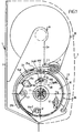
- La figure 1 est une vue de côté d'un appareil distributeur de papier d'essuyage établi sous la coupe A-A de la figure 2.
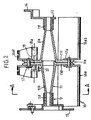
- La figure 2 est une vue en coupe du tambour prise seule illustrant les caractéristiques de l'invention.
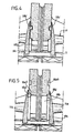
- La figure 3 est une vue de face du tambour en gros plan dans sa position de sélection de format minimum.
- Les figures 4 et 5 sont des vues partielles similaires à la figure 3 représentant le dispositif sélecteur dans les positions moyenne et maximum de la variation du format.
- Les figures 6 et 7 sont des vues selon la coupe A-A de la figure 2 illustrant la position des constituants des tambours dans les phases de distribution de bandes de matériau, selon un format minimum et selon un format maximum.
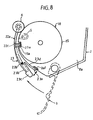
- La figure 8 est une vue de côté partiel à caractère schématique illustrant un verrou de blocage du tambour lors de l'ouverture du couvercle.
- FIG. 1 is a side view of a wiping paper dispensing apparatus established under section AA of FIG. 2.
- Figure 2 is a sectional view of the drum taken alone illustrating the features of the invention.
- Figure 3 is a front view of the drum in close-up in its minimum size selection position.
- Figures 4 and 5 are partial views similar to Figure 3 showing the selector device in the medium and maximum positions of the format variation.
- Figures 6 and 7 are views along section AA of Figure 2 illustrating the position of the constituents of the drums in the material strip distribution phases, in a minimum format and in a maximum format.
- Figure 8 is a partial side view in schematic illustrating a lock for locking the drum when the lid is opened.
Afin de rendre plus concret l'objet de l'invention, on le décrit maintenant d'une manière non limitative illustrée aux figures des dessins.In order to make the object of the invention more concrete, it is now described with a non-limiting manner illustrated in the figures of the drawings.
Pour la compréhension de l'invention, on décrit préalablement un exemple d'un appareil distributeur de matériaux d'essuyage dans lequel le tambour et son dispositif de variation de format peut s'appliquer.To understand the invention, an example of a wiping material dispensing apparatus in which the drum and its format variation device may apply.
L'appareil est référencé dans son ensemble par (1) et comprend un carter (2), un couvercle (3), un tambour, un dispositif de coupe (5) intégré dans le tambour, ainsi que des moyens de lancement et de rappel du tambour incluant un excentrique (7) et un ressort (8). Dans sa partie haute, le carter est agencé avec des flasques (2a) susceptibles de recevoir la porte-bobine (9) d'une bobine de matériau d'essuyage (B). Dans une mise en oeuvre, un élément presseur (6) peut être disposé en appui sur le tambour entre lequel passe le papier en provenance de la bobine. En variante, l'appareil ne comprend pas d'éléments presseur et la bande de papier de la bobine est en appui direct sur le tambour lors de sa traction en vue de sa coupe.The device is referenced as a whole by (1) and comprises a casing (2), a cover (3), a drum, a cutting device (5) integrated in the drum, as well as means for launching and recalling the drum including an eccentric (7) and a spring (8). In its upper part, the casing is arranged with flanges (2a) capable of receiving the reel holder (9) of a reel wiping material (B). In one implementation, a pressing element (6) can be arranged to rest on the drum between which the paper passes origin of the coil. Alternatively, the device does not include elements presser and the reel paper strip is in direct support on the drum when it is pulled for cutting.
Selon l'invention, le tambour est représenté dans son ensemble par (10). Il comprend tout d'abord un moyeu (11) réalisé en deux parties (11a - 11b) présentant à une extrémité une plaque discale (11c - 11d) qui sont juxtaposées l'une contre l'autre pour former une couronne constituant la base d'appui et de fixation d'une pièce profilée susceptible de constituer le pourtour périphérique du cylindre (16) du tambour. According to the invention, the drum is represented as a whole by (10). he first comprises a hub (11) made in two parts (11a - 11b) having at one end a disc plate (11c - 11d) which are juxtaposed one against the other to form a crown constituting the support base and fixing of a profiled part capable of constituting the peripheral periphery of the cylinder (16) of the drum.
Les autres extrémités (11f) des parties (11a - 11b) du moyeu sont susceptibles d'être engagées et solidarisées sur des formes en manchons (12 - 13) solidarisés à des flasques d'extrémité (14 - 15) susceptibles de recevoir le dispositif de coupe (5).The other ends (11f) of the parts (11a - 11b) of the hub are susceptible to be engaged and secured on forms in sleeves (12 - 13) secured to end flanges (14 - 15) capable of receiving the device section (5).
Le flasque (14) associé au manchon (12) présente un prolongement axial à partir duquel est conformé l'excentrique (7) avec doigt (7a) de fixation du ressort de rappel et de lancement du tambour. Le second flasque (15) est agencé pour permettre notamment la fixation du porte-lame du dispositif de coupe.The flange (14) associated with the sleeve (12) has an axial extension to from which the eccentric (7) is shaped with finger (7a) for fixing the drum return and start spring. The second flange (15) is arranged to allow in particular the attachment of the blade holder of the chopped off.
La partie cylindre (16) du tambour et entourant le moyeu est susceptible de s'accoupler sur la couronne (11e) ainsi établie dans une configuration particulière assurant, selon des positions, une variation de la circonférence du tambour et donc en définissant une variation du format de la longueur de la bande de matériau découpé.The cylinder part (16) of the drum and surrounding the hub is capable of mate on the crown (11e) thus established in a configuration particular ensuring, according to positions, a variation of the circumference of the drum and therefore by defining a variation of the format of the length of the strip of cut material.
Selon l'invention, ledit cylindre (16) est en pratique réalisé en deux parties qui sont susceptibles d'avoir un mouvement d'écartement l'une par rapport à l'autre afin de définir la circonférence du tambour et la variation de celui-ci.According to the invention, said cylinder (16) is in practice made in two parts which are likely to have a spreading movement relative to the other in order to define the circumference of the drum and the variation thereof.
Plus particulièrement, le cylindre (16) comprend deux premières parties identiques disposées de part et d'autre de la couronne (11e) du moyeu et comprend un manchon (16a). Ce dernier comprend une partie bague (16a1) disposée en regard et adjacent à la couronne prolongé radialement et vers l'intérieur avec des pattes (16a2). Les plaques discales (11c-11d) définissant la couronne du moyeu sont agencées par ailleurs avec des lumières oblongues curvilignes (11g). Les pattes (16a2) précitées sont disposées en regard desdites lumières, et des moyens de liaison et de fixation (17) assurent leur accouplement. Ces moyens (17) comprennent notamment un axe (17a) qui est susceptible de se déplacer dans lesdites lumières en fonction des mouvements d'écartement entre les premières et secondes parties du cylindre.More particularly, the cylinder (16) comprises two first parts identical arranged on either side of the crown (11e) of the hub and includes a sleeve (16a). The latter includes a ring portion (16a1) arranged opposite and adjacent to the crown extended radially and towards the interior with legs (16a2). The disc plates (11c-11d) defining the hub crowns are also arranged with oblong slots curvilinear (11g). The aforementioned legs (16a2) are arranged opposite said lights, and connecting and fixing means (17) ensure their coupling. These means (17) include in particular an axis (17a) which is capable of moving in said lights as a function of movements spacing between the first and second parts of the cylinder.
Par ailleurs, lesdites bagues de faible largeur sont établies sur approximativement une angulation de 150 à 180°. Elles de prolongent par une portée (16a3) curviligne définissant une partie complémentaire d'appui du cylindre pour la bande de papier tiré. Cette portée est de grande longueur sensiblement jusqu'aux flasques latéraux d'extrémité du tambour porté par le moyeu. Cette portée (16a3) est semi-cylindrique avec des fentes (16a4), jusqu'à aboutir près de la zone de sortie longitudinale du dispositif de coupe hors du tambour. Lesdites fentes établies sur une partie de la longueur des portées assurent une certaine flexibilité permettant la déformation élastique de la première partie du cylindre.Furthermore, said rings of small width are established on approximately an angle of 150 to 180 °. They extend by a curvilinear bearing surface (16a3) defining a complementary support part of the cylinder for the strip of pulled paper. This litter is very long substantially to the end flanges of the end of the drum carried by the hub. This seat (16a3) is semi-cylindrical with slots (16a4), up to end near the longitudinal exit zone of the cutting device outside the drum. Said slots established over part of the length of the spans provide flexibility allowing elastic deformation of the first part of the cylinder.
Selon une autre disposition, la bague de la première partie du cylindre est agencée près de son extrémité libre avec une pluralité de découpes (16a5 - 16a6) établies d'une part en extrémité, et d'autre part le long de sa bordure périphérique extérieure, et dont l'intérêt apparaítra par la suite.According to another arrangement, the ring of the first part of the cylinder is arranged near its free end with a plurality of cutouts (16a5 - 16a6) established on the one hand at the end, and on the other hand along its border external device, and whose interest will appear later.
De par sa configuration, la première partie du cylindre (16) est susceptible d'une certaine déformation élastique par écartement et extension en particulier dans la zone de la bague ainsi établie.Due to its configuration, the first part of the cylinder (16) is susceptible a certain elastic deformation by spacing and extension in particular in the area of the ring thus established.
Il convient de décrire la seconde partie (16b) du cylindre susceptible de coopérer avec la première partie et permettre d'obtenir l'effet et la fonction recherchée de variation de format du papier à découper. It is advisable to describe the second part (16b) of the cylinder capable of cooperate with the first part and achieve the effect and function variation in the size of the paper to be cut.
Cette seconde partie de cylindre est établie sous forme de plaquettes (18) articulées par rapport à la couronne du moyeu. Cette dernière présente de part et d'autre de son plan des portées cylindriques (19) en saillie sur lesquelles sont montées des bagues (18a) associées à chaque plaquette (18). Ces plaquettes sont susceptibles de venir en appui sous-jacent et partiellement sur la partie bague de la première partie du cylindre. Chaque plaquette (18) présente une configuration de profil curviligne avec une zone intérieure (18b) en chevauchement de la partie bague précitée et une zone adjacente (18c) surélevée susceptible d'être dans le même plan que la partie du cylindre à l'état repos.This second cylinder part is established in the form of plates (18) articulated with respect to the hub crown. The latter presents and on the other side of its plane projecting cylindrical spans (19) on which are mounted rings (18a) associated with each plate (18). These plates are likely to come into underlying support and partially on the part ring of the first part of the cylinder. Each plate (18) has a curvilinear profile configuration with an interior area (18b) in overlap of the aforementioned ring part and an adjacent zone (18c) raised likely to be in the same plane as the part of the cylinder in the state rest.
Il y a lieu de préciser que ladite zone (18c) et la surface extérieure de la bague de la première partie de cylindre sont agencées avec une surface rugueuse susceptible de faciliter l'appui et l'entraínement de la bande de papier tiré.It should be noted that said zone (18c) and the outer surface of the ring of the first cylinder part are arranged with a rough surface likely to facilitate the support and training of the strip of pulled paper.
Par ailleurs, la zone intérieure (18b) de chaque plaquette (18) est conformée avec une saillie (18d) de profil et forme correspondant aux échancrures de découpes (16a5 - 16a6) établies sur la partie bague de la première partie de cylindre. Il y a lieu de préciser qu'au moins un ressort de rappel (20) est fixé par une extrémité (20a) par une patte en saillie (21) intérieure établie sur la bague de la première partie de cylindre, son autre extrémité étant fixé à la bague (18) de la plaquette.Furthermore, the inner zone (18b) of each plate (18) is shaped with a projection (18d) of profile and shape corresponding to the notches of cutouts (16a5 - 16a6) established on the ring part of the first part of cylinder. It should be noted that at least one return spring (20) is attached by one end (20a) by an inner projecting tab (21) established on the ring of the first cylinder part, its other end being fixed to the ring (18) of the plate.
Il convient dès lors d'exposer le fonctionnement du tambour et notamment de la conception du cylindre permettant la variation de format de bande de papier à distribuer.It is therefore necessary to explain the operation of the drum and in particular the cylinder design allowing variation of paper tape format to distribute.
En position normale, le cylindre se présente sous forme d'un cercle. La plaquette (18) est en contact avec le fond intérieur de la bague de la première partie de cylindre, tandis que le ressort (20) n'est pas sollicité. L'extrémité libre de la bague de la première partie de cylindre est sensiblement adjacente au dispositif de coupe.In normal position, the cylinder is in the form of a circle. The plate (18) is in contact with the inner bottom of the ring of the first cylinder part, while the spring (20) is not stressed. The free end of the ring of the first cylinder part is substantially adjacent to the cutting device.
Lorsque l'opérateur désire augmenter la longueur du format de papier à distribuer, il faut procéder à l'ouverture du tambour, c'est-à-dire à l'écartement de la première partie de cylindre par rapport à la seconde partie de cylindre pour donner une configuration non circulaire au tambour. A cet égard, l'opérateur, dans une manipulation simple, peut saisir la couronne centrale ou la bague de la première partie de cylindre et l'écarter par rapport à la partie fixe définie par la seconde partie de cylindre, assurant un déplacement des axes de liaison dans les lumières conformées à cet effet. L'amplitude de réglage est effectuée en fonction du format choisi. La forme en saillie établie sur la plaquette est susceptible de venir s'appliquer contre la ou les échancrures ou découpes formés sur la bague de la première partie de cylindre, en assurant ainsi le verrouillage en position de celui-ci. Lors de l'ouverture maximum de la première partie de cylindre, le ressort de rappel (20) est maintenu avec écartement et tension maximum pour l'ouverture maximum de la couronne du cylindre. Les fentes qui ont été formées sur la portée cylindrique de la première partie de cylindre sont susceptibles d'absorber la déformation de celui-ci lors de son ouverture en fonction du format qui a été préétabli.When the operator wishes to increase the length of the paper size to distribute, the drum must be opened, i.e. the spacing of the first cylinder part with respect to the second cylinder part to give a non-circular configuration to the drum. In this regard, the operator, in a simple manipulation, can grasp the central crown or the ring of the first cylinder part and move it away from the fixed part defined by the second cylinder part, ensuring a displacement of the axes of connection in the lights shaped for this purpose. The adjustment range is depending on the format chosen. The protruding shape established on the plate may be applied against the indentation (s) or cutouts formed on the ring of the first cylinder part, ensuring thus locking in position thereof. When the maximum opening of the first part of cylinder, the return spring (20) is held with maximum spacing and tension for maximum opening of the crown cylinder. The slots that were formed on the cylindrical seat of the first cylinder part are likely to absorb the deformation of it during its opening according to the format that has been preset.
La remise à zéro correspondant au format minimum de la bande de matériau tiré, et de la configuration circulaire du tambour exige la sollicitation en pression vers l'intérieur du tambour de la plaquette (18) par pivotement à l'intérieur du tambour. On libère ainsi la ou les zones d'accrochage complémentaires saillie-échancrure établies sur la plaquette et sur la bague de la première partie de cylindre. La détente du ressort de rappel (20) permet de ramener la première partie de cylindre dans sa position initiale représentée figure 4 des dessins.The reset corresponding to the minimum format of the material strip pulled, and the circular configuration of the drum requires the stress in pressure towards the inside of the plate drum (18) by pivoting inside the drum. This frees up the attachment zone (s) additional projection-notch established on the plate and on the ring the first part of the cylinder. The relaxation of the return spring (20) allows return the first cylinder part to its initial position shown Figure 4 of the drawings.
Selon l'invention, le nombre de format possible de la bande de papier à couper est fonction du nombre d'échancrures établies sur la partie bague de la première partie de cylindre.According to the invention, the number of possible formats of the strip of paper to be cut is a function of the number of notches established on the ring part of the first part of cylinder.
La remise à zéro correspondant au format minimum est assurée de manière simple par un effet de pression sur la plaquette (18). Le tambour ainsi décrit peut-être utilisé sur différents types de papier de matériau.The reset corresponding to the minimum format is ensured so simple by a pressure effect on the plate (18). The drum thus described can be used on different types of material paper.
A titre complémentaire des moyens principaux de l'invention, un appareil distributeur du type précité incluant le tambour à format variable, comprend un guide-papier (21) formé en deux parties articulées (21a - 21b) et se fixant par l'une d'elle (21a) par clippage sur la partie centrale du rouleau presseur (6), lorsque celui-ci est présent dans l'appareil.In addition to the main means of the invention, an apparatus dispenser of the aforementioned type including the variable format drum, includes a paper guide (21) formed in two articulated parts (21a - 21b) and fixed by one of them (21a) by clipping onto the central part of the pressure roller (6), when it is present in the device.
En outre, un volet de protection (22) de la lame de coupe est fixé entre les flasques du carter et est monté également avec une capacité d'articulation élastique par un axe (22b) pour tenir compte de la rotation du tambour lors de la coupe selon des formats variés.In addition, a protective flap (22) of the cutting blade is fixed between the casing flanges and is also mounted with an articulation capacity elastic by an axis (22b) to take into account the rotation of the drum during cutting in various formats.
En se référant à la figure 8 des dessins, il est possible d'adjoindre un verrou de blocage (23) du tambour (10) lors de l'ouverture du couvercle (3) soit pour charger l'appareil, soit pour modifier le format de la bande à découper.Referring to Figure 8 of the drawings, it is possible to add a lock blocking (23) of the drum (10) when the cover (3) is opened, either for load the device, either to change the format of the strip to be cut.
Ce verrou se présente sous la forme d'une barrette courbe insérée entre l'un des flasques (2a) du carter et la face (22a) en regard du volet de protection (22). Cette barrette est avantageusement arcrculée sur l'axe (22b) du volet. Cette barrette (23) est agencée dans sa partie supérieure avec une forme en saillie (23a) orientée intérieurement et s'ajuste dans une découpe (22c) aménagée à cet effet sur le volet. La partie basse (23b) de la barrette présente une forme en saillie (23c) débordant vers l'avant en regard du couvercle (3). Cette barrette présente par ailleurs une languette (23d) à capacité élastique de déformation, dont l'extrémité (23e) est susceptible d'être en appui et contact avec une butée (2a - 21) établi sur le flasque. En phase de fonctionnement normal de l'appareil couvercle fermé, ce dernier prend appui sur le bossage d'extrémité de la barrette en provoquant son basculement et en particulier sur sa partie supérieur libérant la rotation du tambour par l'échappement de la saillie supérieur (23a) une encoche (15a) établie sur le flasque (15) du tambour.This lock is in the form of a curved bar inserted between one of the flanges (2a) of the casing and the face (22a) opposite the protective flap (22). This bar is advantageously hooked onto the axis (22b) of the flap. This bar (23) is arranged in its upper part with a projecting shape (23a) oriented internally and fits into a cutout (22c) fitted to this effect on the shutter. The lower part (23b) of the bar has a shape in projection (23c) projecting forward facing the cover (3). This bar also has a tongue (23d) with elastic deformation capacity, whose end (23e) is likely to be in support and contact with a stop (2a - 21) established on the flange. During normal operation of the device cover closed, the latter rests on the end boss of the bar causing its tilting and in particular on its upper part releasing the rotation of the drum by escaping from the upper projection (23a) a notch (15a) established on the flange (15) of the drum.
En phase d'ouverture du couvercle, ce dernier ne vient plus en contact avec le bossage (23c) supprimant l'effet élastique de basculement de la barrette. Celle-ci bascule et est émise à l'action de rappel élastique de sa partie formant languette, elle autorise la pénétration de la forme en saillie (23a) dans l'encoche (15a) lors de la rotation du tambour en assurant le verrouillage en position de ce dernier. Cette disposition de blocage te verrouillage du tambour permet le chargement de l'appareil ou la manipulation du tambour lui-même et de ses parties constitutives pour assurer les réglages de format souhaité.When the lid is open, the latter no longer comes into contact with the boss (23c) eliminating the elastic effect of tilting the bar. This one tilts and is emitted by the elastic return action of its forming part tongue, it allows the penetration of the protruding shape (23a) into the notch (15a) during the rotation of the drum ensuring the locking in position of the latter. This blocking arrangement locks the drum allows the device to be loaded or the drum itself to be manipulated and of its constituent parts to ensure the desired format settings.
Claims (13)
- Drum for dispensing wipe material in a dispensing machine with facility to adjust the format and length of the dispensed material, the machine being of the type comprising a housing (2), a cover (3), the drum comprising a cutting device (15) built into the drum and arranged longitudinally in a slit provided for this purpose, characterised in that drum (10) comprises a hub (11), the central part of which defines a crown (lie) used to fix and adjust the position of the cylindrical part (16) of the drum in various positions to define changes in the format of the length of the strip of material and in that the cylindrical part (16) of the drum is made as two parts which are capable of moving apart due to the elastic deformation of one of the parts of the cylinder in order to define the circumference of the drum and variations in format, it being possible to lock said parts in position relative to each other.
- Drum as claimed in claim 1, characterised in that the drum comprises a hub (11) made as two parts (11a-11b) having, at one end, a disc plate (11c-11d) and located side by side in order to form the crown which provides the basis for supporting and fixing a profiled part capable of setting the peripheral girth of cylinder (16) of the drum, and in that the other ends (11f) of parts (11a-11b) of the hub are capable of fitting into and meshing with sleeve shapes (12-13) joined to end shields (14-15) capable of accommodating the cutting device (5).
- Drum as claimed in claim 2, characterised in that end shield (14) associated with sleeve (12) has an axial extension beyond which it is shaped as a cam (7) with a stud (7a) for attaching a drum start and return spring, and in that the second end shield (15) is designed to allow, in particular, attachment of the blade holder of the cutting device.
- Drum as claimed in claim 2, characterised in that cylinder (16) has two initial identical parts arranged either side of crown (lie) of the hub and in that each initial part comprises a sleeve (16a) with a ring (16a1) located opposite and adjacent to the crown which extends radially and inwardly with tabs (16a2), and in that disc plates (11c-11d) which define the crown of the hub are designed with oblong curved slots (11g), and in that tabs (16a2) are located opposite said slots and are coupled by means of connection and fixing (17).
- Drum as claimed in claim 4, characterised in that there are narrow wings over an angle of approximately 150 to 180° which extend as a curved bearing surface (16a3) which defines a matching part to support the cylinder for the pulled strip of paper, this bearing surface being long and extending substantially as far as the lateral end shields of the drum which is supported by the hub, and in that bearing surface (16a3) is semi-cylindrical and has slits (16a4) which extend close to the longitudinal area where the cutting device is ejected out of the drum, said slits being made over part of the length of the bearing surfaces, thereby ensuring a certain degree of flexibility which allows elastic deformation of the first part of the cylinder.
- Drum as claimed in claim 5, characterised in that the ring of the first part of the cylinder is designed, close to its free end, with a plurality of cut-outs (16a5-16a6) firstly on its end and secondly along its outside peripheral edge.
- Drum as claimed in claim 2, characterised in that the second part of the cylinder is made in the form of small plates (18) which are articulated relative to the crown of the hub and have, either side of its plane, protruding cylindrical bearing surfaces (19) on which rings (18a) each associated with a small plate (18) are mounted, these small plates being capable of coming into partial contact with the bottom of the ring part of the first part of the cylinder.
- Drum as claimed in claim 7, characterised in that each small plate (18) has a curved shape configuration with an internal area (18b) which overlaps above-mentioned ring part and a raised adjacent area (18c) capable of being in the same plane as the part of the cylinder in the idle state, and in that the internal area (18b) of each small plate (18) is designed with a protruding shape (18d) which matches the scalloping cut-outs (16a5-16a6) on the ring part of the first part of the cylinder.
- Drum as claimed in claim 8, characterised in that at least one return spring (20) is attached at one of its ends (20a) by a protruding internal tab (21) on the ring of the first part of the cylinder, its other end being fixed to the ring (18) of the small plate.
- Drum as claimed in claim 1 including a pressure roller (6) which presses against the drum between which the pulled strip of paper passes, characterised in that the variable-format drum comprises a paper guide (21) made as two articulated parts (21a-21b) and is fixed by one of them (21a) by clipping it onto the middle part of pressure roller (6).
- Dispensing machine with facility to adjust the format and length of the dispensed material comprising a dispensing drum as claimed in claim 1, characterised in that a flap (22) to protect the cutting blade is fixed between the end shields of the housing and is also mounted so that it is elastically articulated in order to make allowance for rotation of the drum when the material is cut to the various formats.
- Dispensing machine with facility to adjust the format and length of the dispensed material comprising a dispensing drum as claimed in claims 1, 2 and 11, characterised in that it comprises a bolt (23) for locking drum (10) when cover (3) is opened either to load the machine or to alter the format of the paper to be cut.
- Dispensing machine with facility to adjust the format and length of the dispensed material comprising a drum as claimed in claims 11 and 12, characterised in that the bolt is in the form of a short curved bolt which is inserted between one of the end shields (2a) of the housing and opposite-facing surface (22a) of protective flap (22), this short bar advantageously being articulated on shaft (22b) of the flap, and in that the upper part of short bar (23) is designed with a protruding shape (23a) which faces inwards and tits into a cut-out. (22c) specially provided on the flap, and in that the lower part (23b) of the short bar has a protruding shape (23c) which projects forwards opposite cover (3), and in that the short bar has a tongue (23d) capable of elastic deformation, one end (23e) of which is capable of pressing against and being in contact with a limit stop (2a-21) provided on the end shield.
Applications Claiming Priority (3)
| Application Number | Priority Date | Filing Date | Title |
|---|---|---|---|
| FR9806703 | 1998-05-25 | ||
| FR9806703A FR2778836B1 (en) | 1998-05-25 | 1998-05-25 | DRUM FOR DELIVERY OF WIPING MATERIAL IN A DISPENSING APPARATUS WITH ADJUSTMENT OF THE FORMAT AND LENGTH OF THE MATERIAL DELIVERED |
| PCT/FR1999/000783 WO1999060906A1 (en) | 1998-05-25 | 1999-04-06 | Wiping material dispensing drum in dispensing apparatus with format and length adjustment of the dispensed material |
Publications (2)
| Publication Number | Publication Date |
|---|---|
| EP1083814A1 EP1083814A1 (en) | 2001-03-21 |
| EP1083814B1 true EP1083814B1 (en) | 2003-06-18 |
Family
ID=9526786
Family Applications (1)
| Application Number | Title | Priority Date | Filing Date |
|---|---|---|---|
| EP99911876A Expired - Lifetime EP1083814B1 (en) | 1998-05-25 | 1999-04-06 | Wiping material dispensing drum in dispensing apparatus with format and length adjustment of the dispensed material |
Country Status (9)
| Country | Link |
|---|---|
| US (1) | US6497167B1 (en) |
| EP (1) | EP1083814B1 (en) |
| AT (1) | ATE242992T1 (en) |
| AU (1) | AU3040899A (en) |
| CA (1) | CA2331161A1 (en) |
| DE (1) | DE69908942T2 (en) |
| FR (1) | FR2778836B1 (en) |
| TW (1) | TW402495B (en) |
| WO (1) | WO1999060906A1 (en) |
Families Citing this family (8)
| Publication number | Priority date | Publication date | Assignee | Title |
|---|---|---|---|---|
| FR2848803B1 (en) * | 2002-12-24 | 2005-02-11 | Maurice Granger | DEVICE FOR CONTROLLING THE ROTATION OF THE DRUM OF AN APPARATUS DISPENSING WIPING MATERIAL |
| FR2859367B1 (en) * | 2003-09-05 | 2006-08-11 | Maurice Granger | DEVICE FOR CONTROLLING THE OUTPUT OF A CUTTING BLADE OF A DRUM IN A TOWING EQUIPMENT DISPENSING DEVICE |
| FR2869519B1 (en) * | 2004-04-30 | 2006-06-16 | Maurice Granger | WIPING MATERIAL DISPENSING APPARATUS WITH CUTTING DEVICE INCLUDING FORMAT SELECTION CAPACITY |
| US20070079676A1 (en) * | 2005-10-07 | 2007-04-12 | Global Plastics | Paper dispenser |
| US8258341B2 (en) | 2009-07-10 | 2012-09-04 | E.I. Du Pont De Nemours And Company | Polyfluorosulfonamido amine and intermediate |
| US10271695B2 (en) * | 2015-10-16 | 2019-04-30 | Dispensing Dynamics International, Llc | Paper towel dispenser damping system |
| EP3525643B1 (en) * | 2016-10-13 | 2024-02-28 | Dispensing Dynamics International, LLC | Paper towel dispenser damping system |
| WO2021016047A1 (en) | 2019-07-19 | 2021-01-28 | Dispensing Dynamics International, Inc. | Dispensing systems with floating support rollers |
Family Cites Families (18)
| Publication number | Priority date | Publication date | Assignee | Title |
|---|---|---|---|---|
| US4137805A (en) * | 1977-04-29 | 1979-02-06 | Georgia-Pacific Corporation | Dispenser for flexible sheet material |
| US4404880A (en) * | 1977-10-14 | 1983-09-20 | Georgia-Pacific Corporation | Method for web cutting in rolled sheet material dispensers |
| FR2555975B1 (en) * | 1983-12-06 | 1986-11-21 | Granger Maurice | APPARATUS FOR DISTRIBUTING AND SIMULTANEOUSLY CUTTING TAPES OF WOUND MATERIALS, WITH AT LEAST ONE ROLL OF MATERIAL IN SERVICE |
| US4712461A (en) * | 1985-10-18 | 1987-12-15 | Georgia-Pacific Corporation | Rolled material dispenser with feed roller containing a sliding cutter |
| JPH0659268B2 (en) * | 1989-02-23 | 1994-08-10 | 幸信 渡辺 | Toilet paper automatic feeder |
| US5048386A (en) * | 1989-10-27 | 1991-09-17 | Georgia-Pacific Corporation | Feed mechanism for flexible sheet material dispensers |
| FR2656601B1 (en) * | 1989-12-28 | 1992-04-24 | Maurice Granger | APPARATUS FOR SIMULTANEOUSLY DISPENSING AND CUTTING TAPES OF ROLLED MATERIALS. |
| IE80725B1 (en) * | 1991-02-26 | 1998-12-30 | Georgia Pacific Corp | Method and apparatus for dispensing flexible sheet material |
| FR2679887B1 (en) * | 1991-08-01 | 1993-10-22 | Maurice Granger | APPARATUS FOR DISTRIBUTING AND SIMULTANEOUS CUTTING OF BANDS OF COATED MATERIALS. |
| FR2723932B1 (en) * | 1994-08-29 | 1997-01-24 | Granger Maurice | APPARATUS FOR DISPENSING WIPING MATERIALS WHICH CAN BE DISTRIBUTED IN FOLDED OR UNFOLDED FORM |
| US6145423A (en) * | 1995-09-15 | 2000-11-14 | Moore Business Forms, Inc. | Semi-automatic dispenser for linerless labels |
| FR2739546B1 (en) * | 1995-10-10 | 1997-12-26 | Granger Maurice | APPARATUS FOR DISPENSING WIPING MATERIAL IN AUTOMATIC OR SEMI-AUTOMATIC OPERATION WITH SELECTOR DEVICE |
| FR2743057B1 (en) * | 1996-01-03 | 1998-02-13 | Granger Maurice | APPARATUS FOR DISPENSING WIPING MATERIALS WHICH CAN BE DISTRIBUTED IN FOLDED OR UNFOLDED FORM |
| FR2746781B1 (en) | 1996-04-02 | 1998-04-30 | Granger Maurice | WIPER MATERIAL DISPENSING DRUM IN A DISPENSING APPARATUS WITH ADJUSTMENT OF THE FORMAT OF THE LENGTH OF DEDICATED MATERIAL |
| US6032898A (en) * | 1996-08-29 | 2000-03-07 | Alwin Manufacturing Co. | Multiple roll towel dispenser |
| US6224010B1 (en) * | 1998-01-22 | 2001-05-01 | Perrin Manufacturing Company | Apparatus and method for dispensing paper toweling from a roll of paper toweling |
| DE19820978A1 (en) * | 1998-05-12 | 1999-11-18 | Blatz Wilhelm | Dispenser for paper hand towels |
| US6412679B2 (en) * | 1998-05-20 | 2002-07-02 | Georgia-Pacific Corporation | Paper towel dispenser |
-
1998
- 1998-05-25 FR FR9806703A patent/FR2778836B1/en not_active Expired - Fee Related
-
1999
- 1999-04-06 EP EP99911876A patent/EP1083814B1/en not_active Expired - Lifetime
- 1999-04-06 US US09/700,095 patent/US6497167B1/en not_active Expired - Fee Related
- 1999-04-06 AU AU30408/99A patent/AU3040899A/en not_active Abandoned
- 1999-04-06 AT AT99911876T patent/ATE242992T1/en not_active IP Right Cessation
- 1999-04-06 DE DE69908942T patent/DE69908942T2/en not_active Expired - Fee Related
- 1999-04-06 CA CA002331161A patent/CA2331161A1/en not_active Abandoned
- 1999-04-06 WO PCT/FR1999/000783 patent/WO1999060906A1/en active IP Right Grant
- 1999-04-07 TW TW088105549A patent/TW402495B/en not_active IP Right Cessation
Also Published As
| Publication number | Publication date |
|---|---|
| EP1083814A1 (en) | 2001-03-21 |
| DE69908942T2 (en) | 2004-05-19 |
| US6497167B1 (en) | 2002-12-24 |
| FR2778836B1 (en) | 2000-06-30 |
| WO1999060906A1 (en) | 1999-12-02 |
| FR2778836A1 (en) | 1999-11-26 |
| ATE242992T1 (en) | 2003-07-15 |
| TW402495B (en) | 2000-08-21 |
| CA2331161A1 (en) | 1999-12-02 |
| DE69908942D1 (en) | 2003-07-24 |
| AU3040899A (en) | 1999-12-13 |
Similar Documents
| Publication | Publication Date | Title |
|---|---|---|
| EP1076505B1 (en) | Automatic or semi-automatic wiping material and toilet paper dispenser | |
| EP0682492B1 (en) | Automatic toilet paper and wiping material dispenser | |
| EP0808122B1 (en) | Folded or unfolded wiping material dispenser apparatus | |
| EP0777436B1 (en) | Apparatus for dispensing wiping materials which can be distributed in folded or non folded form | |
| EP1066787A1 (en) | Paperweb roll dispenser with centre feeding out | |
| EP0773737B1 (en) | Apparatus for dispensing wiping materials which can be distributed in folded or unfolded form | |
| EP1083814B1 (en) | Wiping material dispensing drum in dispensing apparatus with format and length adjustment of the dispensed material | |
| EP0854687B1 (en) | Automatic or semi-automatic wiping material dispenser apparatus with a selector device | |
| EP1079721B1 (en) | Wiping material dispensing apparatus | |
| EP1512359B1 (en) | Wiping material dispenser with a control mechanism for the appearance of a cutting blade from a drum in the wiping material dispenser | |
| FR2777770A1 (en) | Automatic or semiautomatic dispenser for tissue, cloth or toilet paper | |
| EP1117320B1 (en) | Apparatus dispensing wiping material in a front position of the reel | |
| CA2386421A1 (en) | Device for distributing wiping material | |
| FR2701016A1 (en) | Dispensing apparatus for wiping materials | |
| EP0681443B1 (en) | Wiping material dispenser | |
| EP0889700B1 (en) | Apparatus for dispensing optionally folded wiping materials | |
| CA2154159C (en) | Automatic wiping material and toilet paper dispenser | |
| FR2717789A1 (en) | Distributor of hand drying paper | |
| FR2742737A1 (en) | Paper towel or wipe dispenser | |
| FR2890302A1 (en) | ASSEMBLY DEVICE FOR BRAKING THE COIL FOR CUTTING IN A DISTRIBUTOR APPARATUS OF AUTOMATIC CUTTING WIPING MATERIALS | |
| FR2853515A1 (en) | Wiping material e.g. toilet paper, dispensing apparatus, has casing coupled to support base that is pivotally connected to another support base, where casing is tilted as function of traction angle of wiping material strip | |
| FR2718937A1 (en) | Dispenser for paper wipes |
Legal Events
| Date | Code | Title | Description |
|---|---|---|---|
| PUAI | Public reference made under article 153(3) epc to a published international application that has entered the european phase |
Free format text: ORIGINAL CODE: 0009012 |
|
| 17P | Request for examination filed |
Effective date: 20001026 |
|
| AK | Designated contracting states |
Kind code of ref document: A1 Designated state(s): AT BE CH CY DE DK ES FI FR GB GR IE IT LI LU MC NL PT SE |
|
| GRAH | Despatch of communication of intention to grant a patent |
Free format text: ORIGINAL CODE: EPIDOS IGRA |
|
| GRAH | Despatch of communication of intention to grant a patent |
Free format text: ORIGINAL CODE: EPIDOS IGRA |
|
| GRAA | (expected) grant |
Free format text: ORIGINAL CODE: 0009210 |
|
| AK | Designated contracting states |
Designated state(s): AT BE CH CY DE DK ES FI FR GB GR IE IT LI LU MC NL PT SE |
|
| PG25 | Lapsed in a contracting state [announced via postgrant information from national office to epo] |
Ref country code: NL Free format text: LAPSE BECAUSE OF FAILURE TO SUBMIT A TRANSLATION OF THE DESCRIPTION OR TO PAY THE FEE WITHIN THE PRESCRIBED TIME-LIMIT Effective date: 20030618 Ref country code: IE Free format text: LAPSE BECAUSE OF FAILURE TO SUBMIT A TRANSLATION OF THE DESCRIPTION OR TO PAY THE FEE WITHIN THE PRESCRIBED TIME-LIMIT Effective date: 20030618 Ref country code: FI Free format text: LAPSE BECAUSE OF FAILURE TO SUBMIT A TRANSLATION OF THE DESCRIPTION OR TO PAY THE FEE WITHIN THE PRESCRIBED TIME-LIMIT Effective date: 20030618 Ref country code: CY Free format text: LAPSE BECAUSE OF FAILURE TO SUBMIT A TRANSLATION OF THE DESCRIPTION OR TO PAY THE FEE WITHIN THE PRESCRIBED TIME-LIMIT Effective date: 20030618 Ref country code: AT Free format text: LAPSE BECAUSE OF FAILURE TO SUBMIT A TRANSLATION OF THE DESCRIPTION OR TO PAY THE FEE WITHIN THE PRESCRIBED TIME-LIMIT Effective date: 20030618 |
|
| REG | Reference to a national code |
Ref country code: GB Ref legal event code: FG4D Free format text: NOT ENGLISH |
|
| REG | Reference to a national code |
Ref country code: CH Ref legal event code: EP |
|
| REG | Reference to a national code |
Ref country code: IE Ref legal event code: FG4D Free format text: FRENCH |
|
| REF | Corresponds to: |
Ref document number: 69908942 Country of ref document: DE Date of ref document: 20030724 Kind code of ref document: P |
|
| PG25 | Lapsed in a contracting state [announced via postgrant information from national office to epo] |
Ref country code: SE Free format text: LAPSE BECAUSE OF FAILURE TO SUBMIT A TRANSLATION OF THE DESCRIPTION OR TO PAY THE FEE WITHIN THE PRESCRIBED TIME-LIMIT Effective date: 20030918 Ref country code: PT Free format text: LAPSE BECAUSE OF FAILURE TO SUBMIT A TRANSLATION OF THE DESCRIPTION OR TO PAY THE FEE WITHIN THE PRESCRIBED TIME-LIMIT Effective date: 20030918 Ref country code: GR Free format text: LAPSE BECAUSE OF FAILURE TO SUBMIT A TRANSLATION OF THE DESCRIPTION OR TO PAY THE FEE WITHIN THE PRESCRIBED TIME-LIMIT Effective date: 20030918 Ref country code: DK Free format text: LAPSE BECAUSE OF FAILURE TO SUBMIT A TRANSLATION OF THE DESCRIPTION OR TO PAY THE FEE WITHIN THE PRESCRIBED TIME-LIMIT Effective date: 20030918 |
|
| PG25 | Lapsed in a contracting state [announced via postgrant information from national office to epo] |
Ref country code: ES Free format text: LAPSE BECAUSE OF FAILURE TO SUBMIT A TRANSLATION OF THE DESCRIPTION OR TO PAY THE FEE WITHIN THE PRESCRIBED TIME-LIMIT Effective date: 20030929 |
|
| GBT | Gb: translation of ep patent filed (gb section 77(6)(a)/1977) |
Effective date: 20031023 |
|
| NLV1 | Nl: lapsed or annulled due to failure to fulfill the requirements of art. 29p and 29m of the patents act | ||
| REG | Reference to a national code |
Ref country code: IE Ref legal event code: FD4D |
|
| PG25 | Lapsed in a contracting state [announced via postgrant information from national office to epo] |
Ref country code: LU Free format text: LAPSE BECAUSE OF NON-PAYMENT OF DUE FEES Effective date: 20040406 Ref country code: GB Free format text: LAPSE BECAUSE OF NON-PAYMENT OF DUE FEES Effective date: 20040406 |
|
| PLBE | No opposition filed within time limit |
Free format text: ORIGINAL CODE: 0009261 |
|
| STAA | Information on the status of an ep patent application or granted ep patent |
Free format text: STATUS: NO OPPOSITION FILED WITHIN TIME LIMIT |
|
| PG25 | Lapsed in a contracting state [announced via postgrant information from national office to epo] |
Ref country code: MC Free format text: LAPSE BECAUSE OF NON-PAYMENT OF DUE FEES Effective date: 20040430 Ref country code: LI Free format text: LAPSE BECAUSE OF NON-PAYMENT OF DUE FEES Effective date: 20040430 Ref country code: CH Free format text: LAPSE BECAUSE OF NON-PAYMENT OF DUE FEES Effective date: 20040430 Ref country code: BE Free format text: LAPSE BECAUSE OF NON-PAYMENT OF DUE FEES Effective date: 20040430 |
|
| 26N | No opposition filed |
Effective date: 20040319 |
|
| BERE | Be: lapsed |
Owner name: *GRANGER MAURICE Effective date: 20040430 |
|
| PG25 | Lapsed in a contracting state [announced via postgrant information from national office to epo] |
Ref country code: DE Free format text: LAPSE BECAUSE OF NON-PAYMENT OF DUE FEES Effective date: 20041103 |
|
| GBPC | Gb: european patent ceased through non-payment of renewal fee | ||
| REG | Reference to a national code |
Ref country code: CH Ref legal event code: PL |
|
| PG25 | Lapsed in a contracting state [announced via postgrant information from national office to epo] |
Ref country code: IT Free format text: LAPSE BECAUSE OF NON-PAYMENT OF DUE FEES;WARNING: LAPSES OF ITALIAN PATENTS WITH EFFECTIVE DATE BEFORE 2007 MAY HAVE OCCURRED AT ANY TIME BEFORE 2007. THE CORRECT EFFECTIVE DATE MAY BE DIFFERENT FROM THE ONE RECORDED. Effective date: 20050406 |
|
| REG | Reference to a national code |
Ref country code: FR Ref legal event code: ST Effective date: 20091231 |
|
| PG25 | Lapsed in a contracting state [announced via postgrant information from national office to epo] |
Ref country code: FR Free format text: LAPSE BECAUSE OF NON-PAYMENT OF DUE FEES Effective date: 20091222 |
|
| PGFP | Annual fee paid to national office [announced via postgrant information from national office to epo] |
Ref country code: FR Payment date: 20080429 Year of fee payment: 10 |