EP1076505B1 - Automatic or semi-automatic wiping material and toilet paper dispenser - Google Patents
Automatic or semi-automatic wiping material and toilet paper dispenser Download PDFInfo
- Publication number
- EP1076505B1 EP1076505B1 EP99911853A EP99911853A EP1076505B1 EP 1076505 B1 EP1076505 B1 EP 1076505B1 EP 99911853 A EP99911853 A EP 99911853A EP 99911853 A EP99911853 A EP 99911853A EP 1076505 B1 EP1076505 B1 EP 1076505B1
- Authority
- EP
- European Patent Office
- Prior art keywords
- drum
- hook
- belt
- dispensing machine
- paper
- Prior art date
- Legal status (The legal status is an assumption and is not a legal conclusion. Google has not performed a legal analysis and makes no representation as to the accuracy of the status listed.)
- Expired - Lifetime
Links
Images


Classifications
-
- A—HUMAN NECESSITIES
- A47—FURNITURE; DOMESTIC ARTICLES OR APPLIANCES; COFFEE MILLS; SPICE MILLS; SUCTION CLEANERS IN GENERAL
- A47K—SANITARY EQUIPMENT NOT OTHERWISE PROVIDED FOR; TOILET ACCESSORIES
- A47K10/00—Body-drying implements; Toilet paper; Holders therefor
- A47K10/24—Towel dispensers, e.g. for piled-up or folded textile towels; Toilet-paper dispensers; Dispensers for piled-up or folded textile towels provided or not with devices for taking-up soiled towels as far as not mechanically driven
- A47K10/32—Dispensers for paper towels or toilet-paper
- A47K10/34—Dispensers for paper towels or toilet-paper dispensing from a web, e.g. with mechanical dispensing means
- A47K10/36—Dispensers for paper towels or toilet-paper dispensing from a web, e.g. with mechanical dispensing means with mechanical dispensing, roll switching or cutting devices
- A47K10/3631—The cutting devices being driven manually
- A47K10/3643—The cutting devices being driven manually by pulling the paper
-
- A—HUMAN NECESSITIES
- A47—FURNITURE; DOMESTIC ARTICLES OR APPLIANCES; COFFEE MILLS; SPICE MILLS; SUCTION CLEANERS IN GENERAL
- A47K—SANITARY EQUIPMENT NOT OTHERWISE PROVIDED FOR; TOILET ACCESSORIES
- A47K10/00—Body-drying implements; Toilet paper; Holders therefor
- A47K10/24—Towel dispensers, e.g. for piled-up or folded textile towels; Toilet-paper dispensers; Dispensers for piled-up or folded textile towels provided or not with devices for taking-up soiled towels as far as not mechanically driven
- A47K10/32—Dispensers for paper towels or toilet-paper
- A47K10/34—Dispensers for paper towels or toilet-paper dispensing from a web, e.g. with mechanical dispensing means
- A47K10/36—Dispensers for paper towels or toilet-paper dispensing from a web, e.g. with mechanical dispensing means with mechanical dispensing, roll switching or cutting devices
- A47K10/3631—The cutting devices being driven manually
- A47K2010/365—Triggering mechanism for the blade
-
- Y—GENERAL TAGGING OF NEW TECHNOLOGICAL DEVELOPMENTS; GENERAL TAGGING OF CROSS-SECTIONAL TECHNOLOGIES SPANNING OVER SEVERAL SECTIONS OF THE IPC; TECHNICAL SUBJECTS COVERED BY FORMER USPC CROSS-REFERENCE ART COLLECTIONS [XRACs] AND DIGESTS
- Y10—TECHNICAL SUBJECTS COVERED BY FORMER USPC
- Y10T—TECHNICAL SUBJECTS COVERED BY FORMER US CLASSIFICATION
- Y10T83/00—Cutting
- Y10T83/889—Tool with either work holder or means to hold work supply
- Y10T83/896—Rotatable wound package supply
Definitions
- the invention relates to the technical sector of distribution devices cellulose wiping paper, crepe paper, and the like intended more particularly for wiping the hands of paper users toilet.
- a dispensing device of the prior art according to the preamble of independent claim 1 is described in WO-A-97/24970.
- the drum has an oversized area on an angular sector of its periphery defined between the edge of the cutting blade passage opening and a line corresponding to the axial end plane of the connecting and attachment axis in end of the eccentric, allowing the drum to be launched for cutting, said complementary zone being in contact with the pressing means substantially retractable in position in a floating assembly to absorb changes in the thickness of the drum during the traction phase of the strip of stretched paper and then cutting said paper.
- a device dispenser for hand towels and toilet paper referenced as a whole by (1). It comprises a casing (2) molded in plastic material capable of receiving in its upper part a reel (3) for supplying wiping material or toilet paper held between upper flanges (4) attached to the assembly fast, on the bottom of the housing or otherwise. Lower flanges (5) are attached and fastened or otherwise mounted on the bottom face (2a) of the housing and are fitted with notches allowing fast fixing and mounting drum (6), which includes a cutting device (7) with a serrated blade (7a).
- This cutting device is particular in the manner described above with a serrated heel mechanism (8) associated with the cutting blade which cooperates with a fixed rack (9) established on the inner blank (5b) of said flange (5) of the casing.
- the drum has a longitudinal opening (6f) allowing passage and exit of the cutting blade.
- the drum is arranged in a known manner corresponding to the teaching of the French patent 76.04664. One end is positioned centered on one of the housing flanges while the other end has an axis (6a) projecting outside the other flange, engaging and anchoring in a corresponding notch on the flange.
- Said axis (6a) has an eccentric shape (6b) whose end (6c) forming a finger constitutes the point of attachment of one end (10a) of a return spring and launch (10), the latter having its other end (10b) fixed to the casing the back of the flange facing.
- the pressing means (11) in the form of a cylinder is of length corresponding to that of the drum and is likely to be in support thereon, being positioned between the aforementioned flanges (5).
- the dispensing apparatus further comprises a non-return device (12) for the reel of wiping material comprising a roller (13) bearing on the reel wiping material; this roller is positioned between the flanges of the housing or on a bent lever (14) subject to an elastic return means (15) fixed to the flange (5) of the housing.
- a belt (16) is capable of surrounding the drum (6) and the anti-loop roller (13).
- the drum is also arranged at one of its ends with a groove allowing the positioning of the belt (16) above training.
- the drum has on a part of its periphery a zone in allowance previously described.
- the receiving groove (6g) of the strap drive (16) with the roller (13) bearing against the roller of the strip paper having an anti-loop function is defined in a manner known by the side wall of the drum (6h) and a flange (17) mounted axially and parallel on the shaft of said drum.
- the throat (6g) is of an appropriate section corresponding to the reception of the drive belt (16) and connection.
- the device according to the invention aims to introduce a device (18) for blocking when the drum stops, this device being established in the form of a hook profile mounted on the axis of the pressure roller (11) with free rotation relative to this one.
- Said hook (18) thus has a central hub shape (18a) positioning on the axis of the pressure roller (11) overflowing thereof, in a position such that the profiled lower part (18b) forming the hook arm is likely to be arranged facing and bearing on the connecting belt (16) connecting the drum (5) and the support roller (13) against the paper roll, in the profiled groove (6g) described above.
- This hook (18) has in this regard on its lower arm (18b) including one end is curved to match the profile of the drum (5) and surround substantially the corresponding belt part (16).
- the free end (18c) said hook (18) internally has roughness (18d) or notching which are profiled, and do not prevent the rotation of the drum during traction of the paper strip by the spacing of said hook as will be specified by the following.
- Said hook present in its upper part (18d) beyond its hub a profiled elastic tongue (18th) whose end has a beak (12f) in return which is likely to bear on the flange (5) opposite the device housing.
- This beak (18f) is constantly in abutment on said flange (5).
- the assembly of the assembly gives the hook a certain elasticity in allowing significant elastic deformation of its lower arm (18b) when the rotation of the drum.
- the belt connecting the roller (13) pressing against the paper roll and the drum (6) tends to cause the spacing of the of said arm (18b) of said hook. This situation corresponds to the pressure roller bearing area (11) on the excess portion formed on the drum.
- an area (19) can be made at the bottom of the gorge. forming a belt blocking plate (16), this plate being located substantially in alignment of the eccentric dead center.
- the belt (16) will likely apply to the aforementioned dish by being pressed itself by the notched end of the above hook.
- the hook (18) control of the rotation of the drum does not have in its upper part elastic tongue.
- the lower part (18b) said hook is profiled so that it can come in its front part (18m) against a protective flap (20) fixedly fixed by snap-fastening between the wings or flanges (5) receiving the drum.
- This component has a certain elasticity of deformation.
- the initial rotation of the drum during the pulling phase of the paper strip causes the unrolling the paper strip and moving the connecting belt between the support roller (13) against the paper roll and the drum (6).
- the belt (16) causes disengagement of the notched or protruding end (18d) of the hook (18) and a front support of the front part (18m) of said hook against the flap (20).
- said hook is in pressing against said flap with an elastic deformation in its upper part.
- the blocking in total position is ensured drum. This prevents the latter from going back so that the strip of paper that is intended to be pulled by the user comes out properly the dispensing device.
Landscapes
- Health & Medical Sciences (AREA)
- Public Health (AREA)
- Replacement Of Web Rolls (AREA)
- Cleaning Implements For Floors, Carpets, Furniture, Walls, And The Like (AREA)
- Containers And Packaging Bodies Having A Special Means To Remove Contents (AREA)
- Unwinding Webs (AREA)
- Bidet-Like Cleaning Device And Other Flush Toilet Accessories (AREA)
- Body Washing Hand Wipes And Brushes (AREA)
- Sanitary Thin Papers (AREA)
Abstract
Description
L'invention se rattache au secteur technique des appareils de distribution de papier d'essuyage en ouate de cellulose, papier crêpé, et matériaux similaires destinés plus particulièrement à l'essuyage des mains des utilisateurs de papier toilette.The invention relates to the technical sector of distribution devices cellulose wiping paper, crepe paper, and the like intended more particularly for wiping the hands of paper users toilet.
Il existe de très nombreux appareils d'essuyage à fonctionnement automatique et le demandeur a développé plusieurs appareils de ce type permettant la distribution de bandes de matériau plié ou non plié. Ces appareils qui font l'objet d'exploitation satisfaisantes sont du type comprenant un carter moulé en matière plastique recevant en partie haute un bobine d'alimentation en matériau d'essuyage, un tambour contenant un dispositif de coupe à lame dentelée, ainsi qu'un moyen presseur assurant l'alimentation de la bande de papier vers le tambour, et la mise en tension du papier. La lame de coupe est articulée dans le tambour en étant mise en mouvement par la coopération d'un talon denté associé à l'axe de la lame de coupe et coopérant avec un moyen à crémaillère positionné fixement et intérieurement sur une des ailes du carter. L'extrémité de ce tambour est associée par ailleurs à un mécanisme de lancement avec excentrique et ressort de rappel décrit et illustré dans le brevet FR 76.04664.There are very many functioning wipers automatic and the applicant has developed several devices of this type allowing the distribution of strips of folded or unfolded material. These devices which are subject to satisfactory operation are of the type comprising a casing molded in plastic material receiving in the upper part a supply coil wiping material, a drum containing a blade cutter serrated, as well as a pressing means ensuring the supply of the strip of paper to the drum, and tensioning the paper. The cutting blade is articulated in the drum being set in motion by the cooperation of a toothed heel associated with the axis of the cutting blade and cooperating with a means to rack fixedly positioned and internally on one of the housing wings. The end of this drum is also associated with a mechanism for launch with eccentric and return spring described and illustrated in the patent FR 76.04664.
Un appareil distributeur de l'art antérieur selon le preambule de la revendication indépendante 1 est décrit dans WO-A-97/24970.A dispensing device of the prior art according to the preamble of independent claim 1 is described in WO-A-97/24970.
Pour répondre à certaines difficultés de coupe rencontrées pour les papiers recyclés notamment du papier de large épaisseur non plié, ou papier plié comprenant plusieurs épaisseurs se juxtaposant, le demandeur a développé un nouvel agencement spécifique du tambour en modifiant la section circulaire initiale de ce dernier par une variation de son profil extérieur par la formation d'une surépaisseur sur une partie de sa périphérie. Cette amélioration a notamment été décrite dans le brevet français n° 2777770 déposé le 24 Avril 1998. Cette modification de la section circulaire permet d'agir dans certaines phases de fonctionnement de l'appareil et de distribution de coupe d'une bande de papier, en assurant une meilleure tension possible de la bande de matériau. Plus particulièrement, selon cette demande de brevet français, le tambour présente sur un secteur angulaire de sa périphérie une zone en surépaisseur définie entre le bord de l'ouverture de passage de la lame de coupe et une ligne correspondant au plan axial d'extrémité de l'axe de liaison et d'accrochage en bout de l'excentrique, permettant le lancement du tambour en vue de la coupe, ladite zone complémentaire étant en contact avec le moyen presseur sensiblement escamotable en position selon un montage flottant pour absorber les modifications de l'épaisseur du tambour lors de la phase de traction de la bande de papier étirée puis de la coupe dudit papier.To respond to certain cutting difficulties encountered for papers recycled, in particular wide unfolded paper, or folded paper comprising several thicknesses juxtaposed, the applicant has developed a new specific arrangement of the drum by modifying the circular section initial of the latter by a variation of its external profile by the formation an extra thickness on part of its periphery. This improvement has notably described in French patent n ° 2777770 filed on April 24 1998. This modification of the circular section makes it possible to act in certain appliance operating phases and strip cutting distribution of paper, ensuring the best possible tension of the strip of material. More particularly, according to this French patent application, the drum has an oversized area on an angular sector of its periphery defined between the edge of the cutting blade passage opening and a line corresponding to the axial end plane of the connecting and attachment axis in end of the eccentric, allowing the drum to be launched for cutting, said complementary zone being in contact with the pressing means substantially retractable in position in a floating assembly to absorb changes in the thickness of the drum during the traction phase of the strip of stretched paper and then cutting said paper.
Compte tenu de la zone en surépaisseur établie sur .le tambour sur un secteur angulaire donné et correspondant à la phase de lancement du tambour pour la coupe, le demandeur a constaté qu'apparaissait une pression minimum sur la bande de papier après la coupe et ce après passage de la zone de surépaisseur. Le demandeur a de ce fait constaté que, de par la réaction du ressort d'excentrique de lancement du tambour, ce dernier avait une tendance à revenir en arrière à l'encontre de son sens de rotation normal, entraínant de ce fait la bande de papier dans un mouvement de retrait partiel, ladite bande ne débordant plus assez, et ne pouvant plus être saisie par l'opérateur.Taking into account the extra thickness area established on the drum on a angular sector given and corresponding to the drum launch phase for cutting, the applicant noted that a minimum pressure appeared on the strip of paper after cutting and this after passing the extra thickness area. The plaintiff has therefore found that, by the reaction of the spring eccentric drum launch, the latter had a tendency to return backwards against its normal direction of rotation, thereby causing the strip of paper in a partial withdrawal movement, said strip not overflowing no longer enough, and can no longer be entered by the operator.
La démarche du demandeur a donc été de supprimer cet inconvénient par l'adjonction d'un dispositif permettant le contrôle de la position du tambour dans l'appareil et en évitant le retour en arrière dudit tambour, selon la partie caractérisante de la revendication indépendante 1. The applicant's approach was therefore to eliminate this drawback by the addition of a device for controlling the position of the drum in the device and avoiding the backward movement of said drum, depending on the part Characterizing the independent claim 1.
Ces caractéristiques et d'autres encore ressortiront bien de la suite de la description.These characteristics and others will become clear from the rest of the description.
Pour fixer l'objet de l'invention illustré d'une manière non limitative aux figures des dessins où :
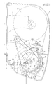
- la figure 1 est une vue de coté de l'appareil distributeur selon l'invention
- la figure 2 est une vue en perspective illustrant un premier mode de mise en oeuvre du dispositif de contrôle en position du tambour.
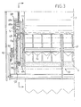
- la figure 3 est une vue de face et en coupe partielle de l'appareil distributeur
- Les figures 4 et 5 sont des vues partielles illustrant le positionnement du dispositif de contrôle de la rotation du tambour par une seconde mise en oeuvre de réalisation, et ce dans les phases de non fonctionnement (figure 4) et de fonctionnement (figure 5).
- Figure 1 is a side view of the dispensing apparatus according to the invention
- Figure 2 is a perspective view illustrating a first embodiment of the control device in the drum position.
- Figure 3 is a front view in partial section of the dispensing apparatus
- Figures 4 and 5 are partial views illustrating the positioning of the device for controlling the rotation of the drum by a second embodiment, and this in the non-operating (Figure 4) and operating (Figure 5) phases.
Afin de rendre plus concret l'objet de l'invention, on le décrit maintenant d'une manière non limitative illustrée aux figures des dessins.In order to make the object of the invention more concrete, it is now described in a nonlimiting manner illustrated in the figures of the drawings.
On rappelle rapidement et succinctement, la conception d'un appareil distributeur pour essuie-mains et papier toilette référencé dans son ensemble par (1). Il comprend un carter (2) moulé en matière plastique susceptible de recevoir dans sa partie haute une bobine (3) d'alimentation en matériau d'essuyage ou papier toilette maintenu entre des flasques (4) supérieurs rapportés à montage rapide, sur le fond du carter ou autrement. Des flasques inférieurs (5) sont rapportés et fixés à montage rapide ou autrement sur la face de fond (2a) du carter et sont aménagés avec des échancrures autorisant la fixation et le montage rapide du tambour (6), lequel inclut un dispositif de coupe (7) à lame dentelée (7a). Ce dispositif de coupe est particulier de la manière décrite précédemment avec un mécanisme à talon (8) dentelé associé à la lame de coupe qui coopère avec une crémaillère fixe (9) établie sur le flan intérieur (5b) de ladite flasque (5) du carter. Le tambour présente une ouverture longitudinale (6f) permettant le passage et la sortie de la lame de coupe. Le tambour est agencé de manière connue correspondant à l'enseignement du brevet français 76.04664. Une extrémité est positionnée centrée sur l'un des flasques du carter tandis que l'autre extrémité présente un axe (6a) en débordement extérieur de l'autre flasque, en s'engageant et s'ancrant dans une échancrure correspondante du flasque. Ledit axe (6a) présente une forme en excentrique (6b) dont l'extrémité (6c) formant doigt constitue le point d'attachement d'une extrémité (10a) d'un ressort de rappel et lancement (10), ce dernier ayant son autre extrémité (10b) fixée au carter à l'arrière du flasque en regard. Le moyen presseur (11) sous forme de cylindre est de longueur correspondante à celle du tambour et est susceptible d'être en appui sur celui-ci, en étant positionné entre les flasques (5) précités.We quickly and succinctly recall the design of a device dispenser for hand towels and toilet paper referenced as a whole by (1). It comprises a casing (2) molded in plastic material capable of receiving in its upper part a reel (3) for supplying wiping material or toilet paper held between upper flanges (4) attached to the assembly fast, on the bottom of the housing or otherwise. Lower flanges (5) are attached and fastened or otherwise mounted on the bottom face (2a) of the housing and are fitted with notches allowing fast fixing and mounting drum (6), which includes a cutting device (7) with a serrated blade (7a). This cutting device is particular in the manner described above with a serrated heel mechanism (8) associated with the cutting blade which cooperates with a fixed rack (9) established on the inner blank (5b) of said flange (5) of the casing. The drum has a longitudinal opening (6f) allowing passage and exit of the cutting blade. The drum is arranged in a known manner corresponding to the teaching of the French patent 76.04664. One end is positioned centered on one of the housing flanges while the other end has an axis (6a) projecting outside the other flange, engaging and anchoring in a corresponding notch on the flange. Said axis (6a) has an eccentric shape (6b) whose end (6c) forming a finger constitutes the point of attachment of one end (10a) of a return spring and launch (10), the latter having its other end (10b) fixed to the casing the back of the flange facing. The pressing means (11) in the form of a cylinder is of length corresponding to that of the drum and is likely to be in support thereon, being positioned between the aforementioned flanges (5).
L'appareil distributeur comprend en outre un dispositif anti-retour (12) de la bobine de matériau d'essuyage comprenant un galet (13) en appui sur la bobine de matériau d'essuyage ; ce galet est positionné entre les flasques du carter ou sur un levier coudé (14) assujetti à un moyen de rappel élastique (15) fixé au flasque (5) du carter. Une courroie (16) est susceptible d'entourer le tambour (6) et le galet (13) anti-boucle. Le tambour est agencé par ailleurs à l'une de ses extrémités avec une gorge permettant le positionnement de la courroie (16) d'entraínement précitée.The dispensing apparatus further comprises a non-return device (12) for the reel of wiping material comprising a roller (13) bearing on the reel wiping material; this roller is positioned between the flanges of the housing or on a bent lever (14) subject to an elastic return means (15) fixed to the flange (5) of the housing. A belt (16) is capable of surrounding the drum (6) and the anti-loop roller (13). The drum is also arranged at one of its ends with a groove allowing the positioning of the belt (16) above training.
Le tambour présente sur une partie de sa périphérie une zone en surépaisseur décrite précédemment. La gorge réceptrice (6g) de la courroie d'entrainement (16) avec le galet (13) d'appui contre le rouleau de la bande papier ayant une fonction anti-boucle, est définie d'une manière connue par la paroi latérale du tambour (6h) et un flasque (17) monté axialement et parallèle sur l'arbre dudit tambour. La gorge (6g) est d'une section appropriée correspondant à la réception de la courroie d'entraínement (16) et de liaison.The drum has on a part of its periphery a zone in allowance previously described. The receiving groove (6g) of the strap drive (16) with the roller (13) bearing against the roller of the strip paper having an anti-loop function, is defined in a manner known by the side wall of the drum (6h) and a flange (17) mounted axially and parallel on the shaft of said drum. The throat (6g) is of an appropriate section corresponding to the reception of the drive belt (16) and connection.
Il convient dès lors de décrire le dispositif objet de l'invention qui a pour but de contrôler la position du tambour et éviter l'effet de retour de ce dernier dans la phase de détente du moyen de rappel (10) élastique et correspondant à la phase de retour du tambour après dépassement par le levier d'excentrique (6b) de son point mort correspondant à l'extension maximum du ressort de rappel (10) de ce dernier.It is therefore necessary to describe the device which is the subject of the invention which has as its purpose of controlling the position of the drum and avoiding the return effect of the latter in the expansion phase of the elastic return means (10) and corresponding to the drum return phase after passing by the eccentric lever (6b) its neutral point corresponding to the maximum extension of the return spring (10) of the last.
Le dispositif selon l'invention vise à introduire un dispositif (18) de blocage en arrêt du tambour, ce dispositif étant établi sous forme d'un crochet profilé monté sur l'axe du rouleau presseur (11) à rotation libre par rapport à celui-ci. Ledit crochet (18) présente ainsi une forme centrale en moyeu (18a) se positionnant sur l'axe du rouleau presseur (11) en débordement de celui-ci, dans une position telle que la partie inférieure profilée (18b) formant bras du crochet est susceptible d'être disposé en regard et en appui sur la courroie de liaison (16) reliant le tambour (5) et le galet d'appui (13) contre le rouleau de papier, dans la gorge profilée (6g) décrite précédemment.The device according to the invention aims to introduce a device (18) for blocking when the drum stops, this device being established in the form of a hook profile mounted on the axis of the pressure roller (11) with free rotation relative to this one. Said hook (18) thus has a central hub shape (18a) positioning on the axis of the pressure roller (11) overflowing thereof, in a position such that the profiled lower part (18b) forming the hook arm is likely to be arranged facing and bearing on the connecting belt (16) connecting the drum (5) and the support roller (13) against the paper roll, in the profiled groove (6g) described above.
Ce crochet (18) présente à cet égard sur son bras inférieur (18b) dont une extrémité est recourbée pour correspondre au profil du tambour (5) et entourer sensiblement la partie de courroie (16) correspondante. L'extrémité libre (18c) dudit crochet (18) présente intérieurement des aspérités (18d) ou crantage qui sont profilées, et qui n'empêchent pas la rotation du tambour lors de la traction de la bande de papier de par l'écartement dudit crochet ainsi qu'il sera précisé par la suite. This hook (18) has in this regard on its lower arm (18b) including one end is curved to match the profile of the drum (5) and surround substantially the corresponding belt part (16). The free end (18c) said hook (18) internally has roughness (18d) or notching which are profiled, and do not prevent the rotation of the drum during traction of the paper strip by the spacing of said hook as will be specified by the following.
Ledit crochet présente dans sa partie supérieure (18d) au-delà de son moyeu une languette élastique profilée (18e) dont l'extrémité présente un bec (12f) en retour qui est susceptible de prendre appui sur le flasque (5) en regard du carter de l'appareil. Ce bec (18f) est constamment en appui sur ledit flasque (5).Said hook present in its upper part (18d) beyond its hub a profiled elastic tongue (18th) whose end has a beak (12f) in return which is likely to bear on the flange (5) opposite the device housing. This beak (18f) is constantly in abutment on said flange (5).
Le montage de l'ensemble confere au crochet une certaine élasticité en autorisant une sensible déformation élastique de son bras inférieur (18b) lors de la rotation du tambour. Lors de la position de lancement du tambour qui correspond à la traction du papier par l'utilisateur, la courroie reliant le galet (13) d'appui contre le rouleau de papier et le tambour (6) a tendance à provoquer l'écartement de la dudit bras (18b) dudit crochet. Cette situation correspond à la zone d'appui du rouleau presseur (11) sur la partie en surépaisseur formée sur le tambour. Lorsque le tambour se trouve dans une situation de lancement maximum avant la coupe correspondant à l'extension maximum du ressort (10) lié à l'excentrique (6c), il se produit ensuite la phase de rotation finale du tambour avec coupe de la bande de matériau ; le rouleau presseur (11) exerce une pression bien moindre sur le tambour par suite de l'échappement d'appui sur la zone de surépaisseur, le bec (18f) et la languette (18e) formées en partie supérieure du crochet (18) ont une sollicitation moindre, et par détente élastique vont permettre le repositionnement de la partie inférieure dudit crochet contre la courroie (16) précitée en assurant le contact par la partie crantée ou en saillie de l'extrémité libre du crochet sur ladite courroie et en évitant ainsi le retour en arrière du tambour.The assembly of the assembly gives the hook a certain elasticity in allowing significant elastic deformation of its lower arm (18b) when the rotation of the drum. During the drum launch position which corresponds to the traction of the paper by the user, the belt connecting the roller (13) pressing against the paper roll and the drum (6) tends to cause the spacing of the of said arm (18b) of said hook. This situation corresponds to the pressure roller bearing area (11) on the excess portion formed on the drum. When the drum is in a launch situation maximum before cutting corresponding to the maximum extension of the spring (10) linked to the eccentric (6c), there then occurs the final rotation phase of the drum with cutting of the strip of material; the pressure roller (11) exerts much less pressure on the drum due to the exhaust bearing on the extra thickness zone, the spout (18f) and the tongue (18e) formed in part upper hook (18) have less stress, and by elastic relaxation will allow the repositioning of the lower part of said hook against the aforementioned belt (16) ensuring contact by the notched or projecting part of the free end of the hook on said belt and thus avoiding the return in back of the drum.
A titre complémentaire il peut être réalisé en fond de gorge une zone (19) formant plat de blocage de la courroie (16) , ce plat étant situé sensiblement dans l'alignement du point mort de l'excentrique. La courroie (16) sera susceptible de s'appliquer sur le plat précité en étant plaquée elle-même par l'extrémité crantée du crochet précité.In addition, an area (19) can be made at the bottom of the gorge. forming a belt blocking plate (16), this plate being located substantially in alignment of the eccentric dead center. The belt (16) will likely apply to the aforementioned dish by being pressed itself by the notched end of the above hook.
Dans une variante de réalisation illustrée aux figures 4 et 5, le crochet (18) de contrôle de la rotation du tambour ne présente pas dans sa partie supérieure de languette élastique. Par contre, dans cette réalisation la partie inférieure (18b) dudit crochet est profilée de manière à pouvoir venir dans sa partie avant (18m) contre un volet de protection (20) monté fixement par encliquetage entre les ailes ou flasques (5) récepteur du tambour. Ce volet présente une certaine élasticité de déformation.In an alternative embodiment illustrated in Figures 4 and 5, the hook (18) control of the rotation of the drum does not have in its upper part elastic tongue. By cons, in this embodiment the lower part (18b) said hook is profiled so that it can come in its front part (18m) against a protective flap (20) fixedly fixed by snap-fastening between the wings or flanges (5) receiving the drum. This component has a certain elasticity of deformation.
Dans cette situation, en se référant aux figures 4 et 5 la rotation initiale du tambour lors de la phase de traction de la bande de papier provoque le déroulement de la bande de papier et le déplacement de la courroie de liaison entre le galet d'appui (13) contre le rouleau de papier et le tambour (6). La courroie (16) provoque un dégagement de l'extrémité crantée ou en saillie (18d) du crochet (18) et un appui frontal de la partie avant (18m) dudit crochet contre le volet (20). En phase de lancement maximum du tambour, ledit crochet est en appui contre ledit volet avec une déformation élastique dans sa partie supérieure. Lors de la phase de retour du tambour correspondant à la zone de coupe, la réduction de la pression entre le rouleau presseur (11) et le tambour (6), ledit crochet (18) est renvoyé en position initiale sous l'effet de détente de la déformation du volet (20) et le crochet (18) reprend sa position initiale venant notamment dans la zone correspondant au plat (19) de blocage correspondant à l'arrêt en position du dit tambour.In this situation, with reference to Figures 4 and 5, the initial rotation of the drum during the pulling phase of the paper strip causes the unrolling the paper strip and moving the connecting belt between the support roller (13) against the paper roll and the drum (6). The belt (16) causes disengagement of the notched or protruding end (18d) of the hook (18) and a front support of the front part (18m) of said hook against the flap (20). In the maximum drum launch phase, said hook is in pressing against said flap with an elastic deformation in its upper part. During the drum return phase corresponding to the cutting area, the pressure reduction between the pressure roller (11) and the drum (6), said hook (18) is returned to the initial position under the relaxation effect of the deformation of the flap (20) and the hook (18) returns to its initial position coming from especially in the area corresponding to the blocking plate (19) corresponding to stopping said drum in position.
Par le dispositif de l'invention, on assure le blocage en position totale du tambour. On évite en effet le retour arrière de ce dernier de sorte que la bande de papier qui est destiné à être tirée par l'utilisateur sort convenablement de l'appareil distributeur.By the device of the invention, the blocking in total position is ensured drum. This prevents the latter from going back so that the strip of paper that is intended to be pulled by the user comes out properly the dispensing device.
Les avantages ressortent bien de l'invention.The advantages emerge clearly from the invention.
Claims (7)
- Automatic or semi-automatic dispensing machine for wipe material and toilet paper of the type comprising a housing (2) accommodating, in its upper part, a supply reel (3) of wipe material, a support drum (6) mounted between the fixed internal end shields (5a) of said housing, said drum (6) having a slit (6f) in order to position and articulate a cutting device (7) with a toothed blade (7a), a pressure means (11) which pushes against drum (6) to ensure the strip of paper which passes between them is transported and tensioned, said cutting blade being articulated inside the drum and being moved through cooperation of a toothed heel (8) associated with the cutting blade and cooperating with a rack gear (9) in a fixed position on one of the end shields of the housing, said drum (6) being associated with a means of starting with a cam (6b) and a return spring (10), the dispensing machine also comprising a wipe reel non-return device and a roller (13) which presses against the reel, a belt (16) which goes round said roller in order to produce a non-return effect, the drum being designed with a profiled groove (6g) which accommodates said belt,
characterised in that drum (6) has, over an angular sector (α) of its periphery, an extra thick area (17) capable of being in contact with pressure means (11) and in that the dispensing machine comprises a drum stop locking device in the form of a shaped hook (18) mounted so that it is freely articulated around the axis of the pressure roller (11), said hook being designed with its lower part forming an arm (18b) capable of being opposite and pressing against belt (16) in the profiled groove, the end of said arm having a protruding shape intended to be in contact with the belt and prevent backward rotation of the drum after the strip of material has been cut. - Dispensing machine as claimed in claim 1 characterised in that the hook has a central hub shape (18a) which positions itself on the shaft of pressure roller (11) and protrudes beyond the latter in a position where the lower shaped part (18b) forming the arm of said hook is capable of being opposite and pressing the belt (16) which connects the drum and the pressure roller which presses against the roll of paper.
- Dispensing machine as claimed in any of claims 1 and 2 characterised in that the upper part of the hook beyond its hub has an elastic shaped tab (18e) the end of which has an angled tip (18f) capable of pressing against the opposite-facing end shield (5) of the housing of the dispensing machine, said tip (18f) pressing against the end shield continuously.
- Dispensing machine as claimed in any of claims 2 and 3 characterised in that the hook has a certain degree of elasticity which allows elastic deformation of its lower arm (18b) due to a counterthrust exerted by the part forming the tip (18f) on end shield (5) so that it is released when belt (16) which connects pressure roller (13) and drum (6) moves normally when the paper is pulled.
- Dispensing machine as claimed in any of claims 1 to 4 characterised in that when the pressure roller exerts pressure on the drum because said pressure roller is no longer in contact with the extra thick area, tip (18f) and tab (18e) formed on the upper part of the hook once again enable contact between the protruding part of the free end of the hook and the belt because of elastic deformation, thereby providing a braking function.
- Dispensing machine as claimed in any of claims 1 to 5 characterised in that there is an area (19) forming a locking flat at the bottom of groove (6g), said locking flat being located essentially in line with the dead centre of the cam, belt (16) being capable of applying itself underneath the aforementioned flat and itself being pressed by the toothed or protruding end of above mentioned hook.
- Dispensing machine as claimed in any of claims 1 to 6 characterised in that the hook has a lower part (18b) shaped so that its front part (18m) moves against a protective flap (20) permanently clicked in on end shield (5) which accommodates the drum, said flap being sufficiently elastically deformable and being actuated when the toothed or protruding part of the hook is released during the phase when the drum is started.
Applications Claiming Priority (3)
| Application Number | Priority Date | Filing Date | Title |
|---|---|---|---|
| FR9805866A FR2778077B1 (en) | 1998-05-04 | 1998-05-04 | APPARATUS FOR DISPENSING WIPING MATERIALS AND AUTOMATIC OR SEMI-AUTOMATIC TOILET PAPER |
| FR9805866 | 1998-05-04 | ||
| PCT/FR1999/000754 WO1999056605A1 (en) | 1998-05-04 | 1999-04-01 | Automatic or semi-automatic wiping material and toilet paper dispenser |
Publications (2)
| Publication Number | Publication Date |
|---|---|
| EP1076505A1 EP1076505A1 (en) | 2001-02-21 |
| EP1076505B1 true EP1076505B1 (en) | 2003-02-05 |
Family
ID=9526182
Family Applications (1)
| Application Number | Title | Priority Date | Filing Date |
|---|---|---|---|
| EP99911853A Expired - Lifetime EP1076505B1 (en) | 1998-05-04 | 1999-04-01 | Automatic or semi-automatic wiping material and toilet paper dispenser |
Country Status (17)
| Country | Link |
|---|---|
| US (1) | US6474209B1 (en) |
| EP (1) | EP1076505B1 (en) |
| JP (1) | JP2002513598A (en) |
| KR (1) | KR100680119B1 (en) |
| CN (1) | CN1115130C (en) |
| AT (1) | ATE232059T1 (en) |
| AU (1) | AU743627B2 (en) |
| BR (1) | BR9910190A (en) |
| CA (1) | CA2331057C (en) |
| DE (1) | DE69905244T2 (en) |
| DK (1) | DK1076505T3 (en) |
| ES (1) | ES2191423T3 (en) |
| FR (1) | FR2778077B1 (en) |
| MX (1) | MXPA00010703A (en) |
| PT (1) | PT1076505E (en) |
| TW (1) | TW387802B (en) |
| WO (1) | WO1999056605A1 (en) |
Families Citing this family (35)
| Publication number | Priority date | Publication date | Assignee | Title |
|---|---|---|---|---|
| FR2791655B1 (en) * | 1999-04-02 | 2001-05-04 | Maurice Granger | CONTROL AND SECURITY DEVICE FOR THE OUTPUT OF STRIPS FOR AN APPARATUS FOR DISTRIBUTING AND SIMULTANEOUS CUTTING OF STRIPS OF WOUND MATERIAL |
| FR2799946B1 (en) * | 1999-10-26 | 2001-11-23 | Maurice Granger | WIPER MATERIAL DISPENSING APPARATUS |
| ES2200950T3 (en) | 1999-10-26 | 2004-03-16 | Maurice Granger | DISTRIBUTING DEVICE OF DRYING MATERIAL. |
| FR2806284B1 (en) * | 2000-03-17 | 2002-05-31 | Maurice Granger | APPARATUS FOR DISPENSING WIPING MATERIAL |
| FR2806285B1 (en) * | 2000-03-17 | 2002-05-31 | Maurice Granger | DEVICE FOR CONTROLLING THE LOADING MECHANISM IN A MATERIAL DISPENSING APPARATUS |
| EP1186270A1 (en) * | 2000-09-08 | 2002-03-13 | Maurice Granger | Controlling device for the load mechanism of a material dispenser |
| FR2816493B1 (en) * | 2000-11-14 | 2003-02-07 | Maurice Granger | ROLL FOR LOADING THE FIRST WEB OF MATERIAL INTO A WIPER PAPER DISPENSER |
| FR2817728B1 (en) * | 2000-12-12 | 2003-03-21 | Maurice Granger | TAPE OUTPUT CONTROL DEVICE IN A MATERIAL DISPENSING APPARATUS |
| FR2817729B1 (en) * | 2000-12-12 | 2003-03-21 | Maurice Granger | LOADING MECHANISM IN A MATERIAL DISPENSING APPARATUS |
| FR2828083B1 (en) | 2001-07-31 | 2003-10-17 | Maurice Granger | ANTI-LOOP COIL FLANGE IN A WIPING MATERIAL DISPENSING APPARATUS |
| FR2828084B1 (en) * | 2001-08-03 | 2003-10-17 | Maurice Granger | WIPER MATERIAL DISPENSING APPARATUS |
| US6910579B2 (en) | 2002-05-28 | 2005-06-28 | Georgia-Pacific Corporation | Refillable flexible sheet dispenser |
| FR2848802B1 (en) * | 2002-12-24 | 2005-02-11 | Maurice Granger | DEVICE FOR CONTROLLING THE ROTATION OF THE DRUM OF AN APPARATUS DISPENSING WIPING MATERIAL |
| FR2859367B1 (en) * | 2003-09-05 | 2006-08-11 | Maurice Granger | DEVICE FOR CONTROLLING THE OUTPUT OF A CUTTING BLADE OF A DRUM IN A TOWING EQUIPMENT DISPENSING DEVICE |
| ES1055751Y (en) * | 2003-10-17 | 2004-04-16 | Escobar Miguel Gonzalez | HYGIENIC PAPER HOLDER. |
| US6959890B1 (en) | 2003-11-19 | 2005-11-01 | Peter Breitinger | Combination adjustable holder to retain premoistened wipes, toilet paper and/or air fresheners and other toilet objects adjacent a toilet |
| DE102004044566A1 (en) * | 2004-03-13 | 2005-09-29 | Joachim Zeusnik | Paper-moistening device for storing/dispensing dry/wet cleaning paper comprises a housing arranged a distance from a roll of paper on a room wall, and guide elements consisting of a trough and a deviating bar guided in a slit-like recess |
| FR2867960B1 (en) * | 2004-03-23 | 2006-11-10 | Maurice Granger | FORMAT SELECTOR DEVICE FOR DISTRIBUTOR APPARATUS FOR WIPING MATERIALS |
| FR2869519B1 (en) * | 2004-04-30 | 2006-06-16 | Maurice Granger | WIPING MATERIAL DISPENSING APPARATUS WITH CUTTING DEVICE INCLUDING FORMAT SELECTION CAPACITY |
| US20050268504A1 (en) * | 2004-06-07 | 2005-12-08 | Haskins Ruby H | Designer object holders |
| US20070145062A1 (en) * | 2005-12-28 | 2007-06-28 | John Formon | Supply roll surface drive for a dispensing apparatus |
| FR2905061B1 (en) * | 2006-08-28 | 2008-10-10 | Maurice Granger | ANTI-LOOP DEVICE AND BRAKE ASSISTANCE IN AN AUTOMATIC CUTTING WIPING MATERIAL DISTRIBUTION APPARATUS. |
| US20100206979A1 (en) * | 2009-02-17 | 2010-08-19 | Collins Scott J | Reset linkage assembly for blocking shield of multi-roll paper dispenser |
| US8763948B1 (en) | 2010-04-27 | 2014-07-01 | Esmonde Holowaty | Electronic toilet tissue dispenser |
| KR100986645B1 (en) | 2010-05-18 | 2010-10-13 | 윤성호 | Apparatus for hanging toilet roll |
| WO2012003866A1 (en) * | 2010-07-07 | 2012-01-12 | Sca Hygiene Products Ab | Dispenser |
| CN102961077A (en) * | 2012-12-06 | 2013-03-13 | 奇塑科技(江阴)有限公司 | Single-hand paper extraction device |
| FR3005402A1 (en) * | 2013-05-07 | 2014-11-14 | Maurice Granger | APPARATUS FOR DISPENSING PREDECUTED, WIRED ROLLING MATERIALS USING A BRAKING DEVICE WITH A BRAKING AND ADJUSTING DEVICE THAT RESULTS IN THE OUTPUT OF THE MATERIAL. |
| US9854948B1 (en) * | 2015-03-31 | 2018-01-02 | Wisconsin Plastics, Inc. | Paper towel dispenser |
| US11395566B2 (en) | 2016-04-11 | 2022-07-26 | Gpcp Ip Holdings Llc | Sheet product dispenser |
| US11412900B2 (en) | 2016-04-11 | 2022-08-16 | Gpcp Ip Holdings Llc | Sheet product dispenser with motor operation sensing |
| US10850938B2 (en) * | 2017-10-09 | 2020-12-01 | Gpcp Ip Holdings Llc | Mechanical sheet product dispenser |
| US10362909B2 (en) * | 2017-11-20 | 2019-07-30 | Guangzhou Faner Aroma Product Co., Ltd. | Paper dispensing device |
| CN108245069B (en) * | 2018-01-10 | 2020-09-01 | 董礼利 | Hand-operated tissue box with automatic tissue breaking function |
| CN108918900B (en) * | 2018-07-20 | 2021-07-27 | 蒋春云 | AIDS sample processing device capable of automatically wiping sidewall hanging drop of sampling needle |
Family Cites Families (9)
| Publication number | Priority date | Publication date | Assignee | Title |
|---|---|---|---|---|
| FR2340887A2 (en) | 1976-02-11 | 1977-09-09 | Granger Maurice | Reel dispenser with simultaneous cutting - has toothed blade inside pressure roller projected by cam action to cut paper automatically |
| US4441392A (en) * | 1981-11-04 | 1984-04-10 | Georgia-Pacific Corporation | Cut web material dispenser with web centering and tension control |
| CN1059318C (en) * | 1993-02-01 | 2000-12-13 | 莫里斯·格朗热 | Automatic toilet paper and wiping material dispenser |
| FR2739546B1 (en) * | 1995-10-10 | 1997-12-26 | Granger Maurice | APPARATUS FOR DISPENSING WIPING MATERIAL IN AUTOMATIC OR SEMI-AUTOMATIC OPERATION WITH SELECTOR DEVICE |
| DE19541510C2 (en) | 1995-11-08 | 1999-08-12 | Karlsruhe Forschzent | Pulsed electron beam source and its use |
| FR2743057B1 (en) * | 1996-01-03 | 1998-02-13 | Granger Maurice | APPARATUS FOR DISPENSING WIPING MATERIALS WHICH CAN BE DISTRIBUTED IN FOLDED OR UNFOLDED FORM |
| FR2777770B1 (en) * | 1998-04-24 | 2000-06-16 | Maurice Granger | APPARATUS FOR DISPENSING WIPING MATERIAL AND TOILET PAPER WITH AUTOMATIC OR SEMI-AUTOMATIC OPERATION |
| FR2779930B1 (en) * | 1998-06-19 | 2000-08-11 | Maurice Granger | DEVICE FOR CONTROLLING AND LIMITING THE ROTATION OF THE DRUM IN A WIPING MATERIAL DISPENSING APPARATUS |
| DE29912713U1 (en) * | 1999-07-21 | 2000-09-14 | Elektro-Thermit GmbH & Co. KG, 45139 Essen | Device for separating excess weld metal |
-
1998
- 1998-05-04 FR FR9805866A patent/FR2778077B1/en not_active Expired - Lifetime
-
1999
- 1999-04-01 JP JP2000546645A patent/JP2002513598A/en not_active Ceased
- 1999-04-01 MX MXPA00010703A patent/MXPA00010703A/en active IP Right Grant
- 1999-04-01 EP EP99911853A patent/EP1076505B1/en not_active Expired - Lifetime
- 1999-04-01 DK DK99911853T patent/DK1076505T3/en active
- 1999-04-01 WO PCT/FR1999/000754 patent/WO1999056605A1/en active IP Right Grant
- 1999-04-01 AT AT99911853T patent/ATE232059T1/en not_active IP Right Cessation
- 1999-04-01 KR KR1020007011885A patent/KR100680119B1/en not_active IP Right Cessation
- 1999-04-01 PT PT99911853T patent/PT1076505E/en unknown
- 1999-04-01 ES ES99911853T patent/ES2191423T3/en not_active Expired - Lifetime
- 1999-04-01 CA CA002331057A patent/CA2331057C/en not_active Expired - Fee Related
- 1999-04-01 DE DE69905244T patent/DE69905244T2/en not_active Expired - Lifetime
- 1999-04-01 AU AU30393/99A patent/AU743627B2/en not_active Ceased
- 1999-04-01 CN CN99805812A patent/CN1115130C/en not_active Expired - Lifetime
- 1999-04-01 US US09/673,408 patent/US6474209B1/en not_active Expired - Lifetime
- 1999-04-01 BR BR9910190-4A patent/BR9910190A/en not_active IP Right Cessation
- 1999-04-06 TW TW088105448A patent/TW387802B/en not_active IP Right Cessation
Also Published As
| Publication number | Publication date |
|---|---|
| DK1076505T3 (en) | 2003-05-19 |
| CN1115130C (en) | 2003-07-23 |
| FR2778077A1 (en) | 1999-11-05 |
| JP2002513598A (en) | 2002-05-14 |
| KR100680119B1 (en) | 2007-02-07 |
| KR20010071181A (en) | 2001-07-28 |
| TW387802B (en) | 2000-04-21 |
| ES2191423T3 (en) | 2003-09-01 |
| AU743627B2 (en) | 2002-01-31 |
| WO1999056605A1 (en) | 1999-11-11 |
| ATE232059T1 (en) | 2003-02-15 |
| CN1299246A (en) | 2001-06-13 |
| DE69905244D1 (en) | 2003-03-13 |
| DE69905244T2 (en) | 2003-11-13 |
| AU3039399A (en) | 1999-11-23 |
| FR2778077B1 (en) | 2000-06-16 |
| PT1076505E (en) | 2003-06-30 |
| CA2331057A1 (en) | 1999-11-11 |
| MXPA00010703A (en) | 2002-04-24 |
| CA2331057C (en) | 2007-05-29 |
| EP1076505A1 (en) | 2001-02-21 |
| BR9910190A (en) | 2001-01-02 |
| US6474209B1 (en) | 2002-11-05 |
Similar Documents
| Publication | Publication Date | Title |
|---|---|---|
| EP1076505B1 (en) | Automatic or semi-automatic wiping material and toilet paper dispenser | |
| EP0808122B1 (en) | Folded or unfolded wiping material dispenser apparatus | |
| EP0777436B1 (en) | Apparatus for dispensing wiping materials which can be distributed in folded or non folded form | |
| EP1073360B1 (en) | Automatic or semiautomatic wiping material and toilet paper dispensing apparatus | |
| EP1164906B1 (en) | Safety device for strip dispenser | |
| EP0773737B1 (en) | Apparatus for dispensing wiping materials which can be distributed in folded or unfolded form | |
| EP1463431B1 (en) | Device for controlling and repositioning a roll of wiping material in an automatic-cutting dispenser | |
| EP1079721A1 (en) | Wiping material dispensing apparatus | |
| EP1117320B1 (en) | Apparatus dispensing wiping material in a front position of the reel | |
| EP1083815B1 (en) | Wiping material and toilet paper dispensing apparatus with automatic or semiautomatic functioning | |
| EP1083814B1 (en) | Wiping material dispensing drum in dispensing apparatus with format and length adjustment of the dispensed material | |
| FR2701016A1 (en) | Dispensing apparatus for wiping materials | |
| FR2742737A1 (en) | Paper towel or wipe dispenser | |
| EP0889700B1 (en) | Apparatus for dispensing optionally folded wiping materials | |
| FR2891723A1 (en) | ASSEMBLY DEVICE FOR BRAKING THE COIL FOR CUTTING IN A DISPENSER APPARATUS FOR AUTOMATICALLY CUTTING WIPING MATERIALS | |
| FR2717789A1 (en) | Distributor of hand drying paper | |
| WO2007026103A1 (en) | Device for controlling the braking of a roll for cutting purposes in an automatic-cutting dispenser for wiping materials |
Legal Events
| Date | Code | Title | Description |
|---|---|---|---|
| PUAI | Public reference made under article 153(3) epc to a published international application that has entered the european phase |
Free format text: ORIGINAL CODE: 0009012 |
|
| 17P | Request for examination filed |
Effective date: 20001006 |
|
| AK | Designated contracting states |
Kind code of ref document: A1 Designated state(s): AT BE CH CY DE DK ES FI FR GB GR IE IT LI LU MC NL PT SE |
|
| GRAH | Despatch of communication of intention to grant a patent |
Free format text: ORIGINAL CODE: EPIDOS IGRA |
|
| GRAH | Despatch of communication of intention to grant a patent |
Free format text: ORIGINAL CODE: EPIDOS IGRA |
|
| GRAA | (expected) grant |
Free format text: ORIGINAL CODE: 0009210 |
|
| AK | Designated contracting states |
Designated state(s): AT BE CH CY DE DK ES FI FR GB GR IE IT LI LU MC NL PT SE |
|
| REG | Reference to a national code |
Ref country code: GB Ref legal event code: FG4D Free format text: NOT ENGLISH |
|
| REG | Reference to a national code |
Ref country code: CH Ref legal event code: EP |
|
| REG | Reference to a national code |
Ref country code: IE Ref legal event code: FG4D Free format text: FRENCH |
|
| PGFP | Annual fee paid to national office [announced via postgrant information from national office to epo] |
Ref country code: AT Payment date: 20030313 Year of fee payment: 5 |
|
| REF | Corresponds to: |
Ref document number: 69905244 Country of ref document: DE Date of ref document: 20030313 Kind code of ref document: P |
|
| PGFP | Annual fee paid to national office [announced via postgrant information from national office to epo] |
Ref country code: MC Payment date: 20030317 Year of fee payment: 5 |
|
| PGFP | Annual fee paid to national office [announced via postgrant information from national office to epo] |
Ref country code: LU Payment date: 20030324 Year of fee payment: 5 |
|
| PGFP | Annual fee paid to national office [announced via postgrant information from national office to epo] |
Ref country code: GR Payment date: 20030327 Year of fee payment: 5 |
|
| PGFP | Annual fee paid to national office [announced via postgrant information from national office to epo] |
Ref country code: IE Payment date: 20030328 Year of fee payment: 5 |
|
| PG25 | Lapsed in a contracting state [announced via postgrant information from national office to epo] |
Ref country code: CY Free format text: LAPSE BECAUSE OF FAILURE TO SUBMIT A TRANSLATION OF THE DESCRIPTION OR TO PAY THE FEE WITHIN THE PRESCRIBED TIME-LIMIT Effective date: 20030401 |
|
| PGFP | Annual fee paid to national office [announced via postgrant information from national office to epo] |
Ref country code: CH Payment date: 20030411 Year of fee payment: 5 |
|
| PGFP | Annual fee paid to national office [announced via postgrant information from national office to epo] |
Ref country code: BE Payment date: 20030429 Year of fee payment: 5 |
|
| PGFP | Annual fee paid to national office [announced via postgrant information from national office to epo] |
Ref country code: DK Payment date: 20030430 Year of fee payment: 5 |
|
| REG | Reference to a national code |
Ref country code: DK Ref legal event code: T3 Ref country code: GR Ref legal event code: EP Ref document number: 20030401501 Country of ref document: GR |
|
| REG | Reference to a national code |
Ref country code: SE Ref legal event code: TRGR |
|
| PGFP | Annual fee paid to national office [announced via postgrant information from national office to epo] |
Ref country code: PT Payment date: 20030530 Year of fee payment: 5 |
|
| GBT | Gb: translation of ep patent filed (gb section 77(6)(a)/1977) |
Effective date: 20030509 |
|
| REG | Reference to a national code |
Ref country code: PT Ref legal event code: SC4A Free format text: AVAILABILITY OF NATIONAL TRANSLATION Effective date: 20030429 |
|
| REG | Reference to a national code |
Ref country code: ES Ref legal event code: FG2A Ref document number: 2191423 Country of ref document: ES Kind code of ref document: T3 |
|
| PLBE | No opposition filed within time limit |
Free format text: ORIGINAL CODE: 0009261 |
|
| STAA | Information on the status of an ep patent application or granted ep patent |
Free format text: STATUS: NO OPPOSITION FILED WITHIN TIME LIMIT |
|
| PG25 | Lapsed in a contracting state [announced via postgrant information from national office to epo] |
Ref country code: FR Free format text: LAPSE BECAUSE OF NON-PAYMENT OF DUE FEES Effective date: 20031231 |
|
| 26N | No opposition filed |
Effective date: 20031106 |
|
| REG | Reference to a national code |
Ref country code: FR Ref legal event code: ST |
|
| PG25 | Lapsed in a contracting state [announced via postgrant information from national office to epo] |
Ref country code: LU Free format text: LAPSE BECAUSE OF NON-PAYMENT OF DUE FEES Effective date: 20040401 Ref country code: IE Free format text: LAPSE BECAUSE OF NON-PAYMENT OF DUE FEES Effective date: 20040401 Ref country code: AT Free format text: LAPSE BECAUSE OF NON-PAYMENT OF DUE FEES Effective date: 20040401 |
|
| PG25 | Lapsed in a contracting state [announced via postgrant information from national office to epo] |
Ref country code: MC Free format text: LAPSE BECAUSE OF NON-PAYMENT OF DUE FEES Effective date: 20040430 Ref country code: LI Free format text: LAPSE BECAUSE OF NON-PAYMENT OF DUE FEES Effective date: 20040430 Ref country code: DK Free format text: LAPSE BECAUSE OF NON-PAYMENT OF DUE FEES Effective date: 20040430 Ref country code: CH Free format text: LAPSE BECAUSE OF NON-PAYMENT OF DUE FEES Effective date: 20040430 Ref country code: BE Free format text: LAPSE BECAUSE OF NON-PAYMENT OF DUE FEES Effective date: 20040430 |
|
| PG25 | Lapsed in a contracting state [announced via postgrant information from national office to epo] |
Ref country code: PT Free format text: LAPSE BECAUSE OF NON-PAYMENT OF DUE FEES Effective date: 20041015 |
|
| BERE | Be: lapsed |
Owner name: *GRANGER MAURICE Effective date: 20040430 |
|
| PG25 | Lapsed in a contracting state [announced via postgrant information from national office to epo] |
Ref country code: GR Free format text: LAPSE BECAUSE OF NON-PAYMENT OF DUE FEES Effective date: 20041103 |
|
| REG | Reference to a national code |
Ref country code: CH Ref legal event code: PL |
|
| REG | Reference to a national code |
Ref country code: IE Ref legal event code: MM4A |
|
| PGFP | Annual fee paid to national office [announced via postgrant information from national office to epo] |
Ref country code: FI Payment date: 20080402 Year of fee payment: 10 |
|
| PGFP | Annual fee paid to national office [announced via postgrant information from national office to epo] |
Ref country code: NL Payment date: 20080319 Year of fee payment: 10 |
|
| NLV4 | Nl: lapsed or anulled due to non-payment of the annual fee |
Effective date: 20091101 |
|
| PG25 | Lapsed in a contracting state [announced via postgrant information from national office to epo] |
Ref country code: FI Free format text: LAPSE BECAUSE OF NON-PAYMENT OF DUE FEES Effective date: 20090401 |
|
| PG25 | Lapsed in a contracting state [announced via postgrant information from national office to epo] |
Ref country code: NL Free format text: LAPSE BECAUSE OF NON-PAYMENT OF DUE FEES Effective date: 20091101 |
|
| PGFP | Annual fee paid to national office [announced via postgrant information from national office to epo] |
Ref country code: ES Payment date: 20180531 Year of fee payment: 20 Ref country code: DE Payment date: 20180409 Year of fee payment: 20 |
|
| PGFP | Annual fee paid to national office [announced via postgrant information from national office to epo] |
Ref country code: IT Payment date: 20180417 Year of fee payment: 20 |
|
| PGFP | Annual fee paid to national office [announced via postgrant information from national office to epo] |
Ref country code: SE Payment date: 20180413 Year of fee payment: 20 |
|
| PGFP | Annual fee paid to national office [announced via postgrant information from national office to epo] |
Ref country code: GB Payment date: 20180417 Year of fee payment: 20 |
|
| REG | Reference to a national code |
Ref country code: DE Ref legal event code: R071 Ref document number: 69905244 Country of ref document: DE |
|
| REG | Reference to a national code |
Ref country code: GB Ref legal event code: PE20 Expiry date: 20190331 |
|
| PG25 | Lapsed in a contracting state [announced via postgrant information from national office to epo] |
Ref country code: GB Free format text: LAPSE BECAUSE OF EXPIRATION OF PROTECTION Effective date: 20190331 |
|
| REG | Reference to a national code |
Ref country code: SE Ref legal event code: EUG |
|
| REG | Reference to a national code |
Ref country code: ES Ref legal event code: FD2A Effective date: 20200904 |
|
| PG25 | Lapsed in a contracting state [announced via postgrant information from national office to epo] |
Ref country code: ES Free format text: LAPSE BECAUSE OF EXPIRATION OF PROTECTION Effective date: 20190402 |