EP1083710A2 - Verfahren und Vorrichtung zur ATM Gruppe-Schutzumschaltung - Google Patents
Verfahren und Vorrichtung zur ATM Gruppe-Schutzumschaltung Download PDFInfo
- Publication number
- EP1083710A2 EP1083710A2 EP00307793A EP00307793A EP1083710A2 EP 1083710 A2 EP1083710 A2 EP 1083710A2 EP 00307793 A EP00307793 A EP 00307793A EP 00307793 A EP00307793 A EP 00307793A EP 1083710 A2 EP1083710 A2 EP 1083710A2
- Authority
- EP
- European Patent Office
- Prior art keywords
- atm
- channels
- cells
- paths
- group
- Prior art date
- Legal status (The legal status is an assumption and is not a legal conclusion. Google has not performed a legal analysis and makes no representation as to the accuracy of the status listed.)
- Withdrawn
Links
Images


Classifications
-
- H—ELECTRICITY
- H04—ELECTRIC COMMUNICATION TECHNIQUE
- H04L—TRANSMISSION OF DIGITAL INFORMATION, e.g. TELEGRAPHIC COMMUNICATION
- H04L49/00—Packet switching elements
- H04L49/30—Peripheral units, e.g. input or output ports
- H04L49/3081—ATM peripheral units, e.g. policing, insertion or extraction
-
- H—ELECTRICITY
- H04—ELECTRIC COMMUNICATION TECHNIQUE
- H04L—TRANSMISSION OF DIGITAL INFORMATION, e.g. TELEGRAPHIC COMMUNICATION
- H04L49/00—Packet switching elements
- H04L49/55—Prevention, detection or correction of errors
- H04L49/552—Prevention, detection or correction of errors by ensuring the integrity of packets received through redundant connections
-
- H—ELECTRICITY
- H04—ELECTRIC COMMUNICATION TECHNIQUE
- H04Q—SELECTING
- H04Q11/00—Selecting arrangements for multiplex systems
- H04Q11/04—Selecting arrangements for multiplex systems for time-division multiplexing
- H04Q11/0428—Integrated services digital network, i.e. systems for transmission of different types of digitised signals, e.g. speech, data, telecentral, television signals
- H04Q11/0478—Provisions for broadband connections
-
- H—ELECTRICITY
- H04—ELECTRIC COMMUNICATION TECHNIQUE
- H04L—TRANSMISSION OF DIGITAL INFORMATION, e.g. TELEGRAPHIC COMMUNICATION
- H04L12/00—Data switching networks
- H04L12/54—Store-and-forward switching systems
- H04L12/56—Packet switching systems
- H04L12/5601—Transfer mode dependent, e.g. ATM
- H04L2012/5625—Operations, administration and maintenance [OAM]
- H04L2012/5627—Fault tolerance and recovery
-
- H—ELECTRICITY
- H04—ELECTRIC COMMUNICATION TECHNIQUE
- H04L—TRANSMISSION OF DIGITAL INFORMATION, e.g. TELEGRAPHIC COMMUNICATION
- H04L12/00—Data switching networks
- H04L12/54—Store-and-forward switching systems
- H04L12/56—Packet switching systems
- H04L12/5601—Transfer mode dependent, e.g. ATM
- H04L2012/5629—Admission control
- H04L2012/5631—Resource management and allocation
- H04L2012/5636—Monitoring or policing, e.g. compliance with allocated rate, corrective actions
-
- H—ELECTRICITY
- H04—ELECTRIC COMMUNICATION TECHNIQUE
- H04L—TRANSMISSION OF DIGITAL INFORMATION, e.g. TELEGRAPHIC COMMUNICATION
- H04L49/00—Packet switching elements
- H04L49/25—Routing or path finding in a switch fabric
- H04L49/253—Routing or path finding in a switch fabric using establishment or release of connections between ports
- H04L49/254—Centralised controller, i.e. arbitration or scheduling
-
- H—ELECTRICITY
- H04—ELECTRIC COMMUNICATION TECHNIQUE
- H04L—TRANSMISSION OF DIGITAL INFORMATION, e.g. TELEGRAPHIC COMMUNICATION
- H04L49/00—Packet switching elements
- H04L49/30—Peripheral units, e.g. input or output ports
Definitions
- the present invention relates to asynchronous transfer mode ("ATM") networks, and more particularly to a method and apparatus for detecting and reacting to defects on such a network.
- ATM asynchronous transfer mode
- Synchronous optical networks detect network defects and switch the routing of traffic within the network along differing physical paths in the presence of a defect, to ensure data traffic delivery between end points. Such switching is typically referred to as "protection switching”.
- Modem ATM networks as for example detailed in International Telecommunication Union Recommendations ITU-T I.326, I.361, I.610, I.630, and I.732, support similar protection switching in the presence of defects to provide a signal across the network in the presence of signal failure (signal fail - "SF"), or in the presence of a degraded signal (signal degrade - "SD").
- signal failure signal failure
- ATM protection switching may be effected for single virtual channels ("VC"s); virtual paths ("VP”s); and logical groups of VPs or VCs ("VPG"s or "VCG”s).
- ITU-T Recommendation I.630 suggests that a SF may be detected at the physical layer.
- SD typically manifests itself in the presence of bit errors within the ATM signal.
- ITU-T Recommendation I.630 suggests detecting SD within VCs at the ATM layer, by using performance monitoring ("PM") cells. That is, PM cells that may be used to assess the presence of signal degrade are inserted into an ATM stream. Using these inserted PM cells, the quality of user cells may be assessed at a downstream node.
- PM performance monitoring
- ITU-T Recommendation I.630 does not address a mechanism for effecting protection switching for VPs, VPGs or VCGs in the presence of SD.
- PM flows for all VCs within a VP, VPG or VCG would require undue network resources, in order to monitor such flows on all VPs within a VPG or all VCs within a VCG.
- SD is monitored on a subset of VPs within a VPG or within a subset of VCs within a VCG. If SD is detected on this subset of VPs or VCs, all VPs or VCs within the VPG or VCG are switched from a working entity to a protection entity.
- receipt of traffic is switched from a group of working ATM channels/paths to a group of protection ATM channels/paths on a network element in an ATM network.
- ATM monitoring cells are received on a subset of ATM channels/paths of the group of working ATM channels/paths.
- Each of the ATM monitoring cells includes an error detection code for a plurality of ATM cells received at the network element within an associated ATM channel/path.
- the network element receives the traffic from all channels within the group of protection ATM channels/paths in favour of receiving the traffic on the group of working ATM channels/paths.
- SD need only be monitored on a subset of VCs or VPs within a VCG or VPG, network resources are conserved.
- Network elements and software may embody these methods.
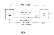
- FIG.1 illustrates ATM NEs 12a , 12b , (collectively, or individually 12 ) forming part of an ATM network, and exemplary of embodiments of the present invention.
- the ATM network will be formed upon a physical network, adhering to a physical layer protocol.
- This physical network may for example, be a Synchronous Optical Network ("SONET"), as it is called in North America, or its European counterpart, a Synchronous Digital Hierarchy (SDH). It may also be a DSn based telephony network.
- SONET Synchronous Optical Network
- SDH Synchronous Digital Hierarchy
- NEs 12 may be conventional ATM switches. NEs 12 may be end nodes with which traffic originates on the ATM network, or intermediate nodes connected between end nodes. As illustrated, NEs 12 are communicatively coupled by at least two links (hereafter referred to as "entities") 14 and 16 capable of transporting payload traffic between NEs 12a and 12b . As will become apparent, third and fourth links 18 and 20 , used to carry out-of band signaling messages may further connect NEs 12 . Entities 14 and 16 and links 18 , 20 may directly connect NEs 12a and 12b , or alternatively couple NEs 12a and 12b by way of intermediate NEs (not illustrated). For simplicity of illustration, entities 14 and 16 and links 18 and 20 are illustrated as bi-directional links.
- Each entity 14 or 16 , and links 18 or 20 is intended to represent two unidirectional links, with one carrying traffic from NE 12a to NE 12b , and the other from NE 12b to NE 12a .
- each unidirectional link may be logically and physically separate from another associated unidirectional link.
- NEs 12 exchange communications traffic in accordance with known ATM protocols. Specifically, prior to the exchange of payload traffic, one or more virtual circuits for the exchange of payload data is negotiated between end NEs on the network. Each virtual circuit is made up of a series of virtual channels ("VC"s) carried on physical connections between adjacent nodes on the network.
- VC virtual channels
- each of entities 14, 16 is intended to represent an entity transporting logical groups of VCs, between nodes 12a and 12b .
- entities 14 and 16 could alternatively transport single VCs; virtual paths("VP"s); or groups of VPs between nodes 12a and 12b .
- Links 18 and 20 are intended to represent single channels (or a series of channels) between NEs 12a and 12b .
- entities 14 and 16 are physically as well as logically separate. However, as will be appreciated, any two or more of entities 14 , 16 and links 18 , 20 may follow the same physical route between NEs 12 .
- Traffic is exchanged between NEs 12 in packets.
- Each packet has fifty-three bytes and is known as a "cell".
- Each cell includes a five byte header.
- the cell header includes a payload type identifier ("PTI"), a virtual channel identifier (“VCI”) associated with the cell, and a virtual path identifier ("VPI").
- the VPI identifies a path between two nodes, while a VCI identifies a channel along such a path. If NEs 12 are adjacent to each other, all traffic passing from NEs 12a to 12b associated with a particular virtual circuit is transported on a virtual channel ("VC") between NEs 12a and 12b .
- VC virtual channel
- the VC may be uniquely identified by a VPI/VCI pair contained in cells transferred between NEs 12a and 12b .
- a routing table maintained at NE 12 a allows NEs 12a to switch all traffic arriving at the input of NE 12a in one VC to another VC associated with a unique VPI/VCI pair at the output of NE 12a .
- NE 12b switches cells associated with a VC at the input of NE 12b to a single VC associated with a unique VPI/VCI pair at the output of NE 12b .
- All cells associated with a virtual circuit are routed along a defined route along the network.
- a virtual circuit between end-nodes on an ATM network is thus identified by a series of VPI/VCI pairs, across the network.
- a secondary channel may also be negotiated between NEs 12a and 12b .
- a primary channel is typically referred to as a working channel.
- secondary channels may negotiate for a virtual circuit across the network, or for a portion of a virtual circuit across the network.
- a secondary channel is often referred to as a protection channel carried on a protection entity, and may be used to carry traffic normally transported by a working channel, in the event of a defect.
- ITU-T Recommendation I.630 details ATM layer protection switching, from a working channel to a protection channel, performed in response to the detection of certain defects. Such protection switching at the ATM layer should avoid contentions between any protection switching available at the physical layer of the network. Preferably, then, when SONET is used as a physical layer for an ATM network, SONET protection switching is disabled in order to avoid such contention.
- Protection switching may be supported for a single VC (i.e. a single VPI/VCI pair) between two nodes ("VC protection switching"), or for all VCs within a virtual path ("VP protection switching").
- VPG virtual path or virtual channel groups
- VCG virtual path or virtual channel groups
- NEs 12a and 12b are configured to group VCs in VCGs, in manners understood by those of ordinary skill in the art.
- a relationship identifying VCs within a VCG is maintained within the memory of each NE 12a and 12b .
- An example configuration of NEs configured for VCG or VPG protection switching is detailed in U.S. Patent No. 5,838,924.
- protection switching for VPGs and VCGs is established for an entire VCG or VPG, based on data associating various VCs within a VCG or VPs within a VPG, and stored at each NE. That is, in the event a defect is detected on any working VC or VP within the group at an NE, traffic carried by the entire VCG or VPG may be switched to the established protection entity for the VPG or VCG by an NE 12a or 12b .
- entity 16 transports a logical group of protection channels for a logical group of working channels on entity 14 .
- NEs 12a and 12b In addition to exchanging payload carrying ("user") cells, NEs 12a and 12b further exchange operations and management (“OAM”) cells dedicated to the management of nodes 12 the associated ATM network.
- OAM operations and management
- ITU-T I.610 and I.630 the format of OAM cells is defined in ITU Recommendations ITU-T I.610 and I.630. OAM cells are identified by the values of the PTI or VCI fields of the cell header.
- OAM cells specific to a VC may be identified by a PTI field value (binary) of 100 (4) or 101 (5). Sequential VC specific OAM cells passed within a VP or VC are referred to as F4 or F5 flows. F4 and F5 flows are carried in band for a specific channel and are identified by the VC's VPI/VCI pair contained in the OAM cell header. Alternatively, OAM cells specific to an entire VP are identified by VCI value of 3 or 4. VP specific CAM cells are carried in band for a specific VP identified by its VPI contained in the OAM cell header.
- Protection switching i.e. the switching of traffic from a working ATM entity to a protection entity, is accomplished through the exchange of OAM cells, generated in response to certain sensed conditions.
- OAM cells may be transported in-band along each affected VP or VC, and are identified by VPI/VCI pairs identical to the protected VC.
- a dedicated out-of-band OAM channel used for protection switching may be provisioned and associated with a VPG or VCG.
- This dedicated OAM channel acts as a signaling channel and is referred to as an OAM ATM Protection Switching ("APS") channel, and is identified between NEs by its own unique VPI/VCI pair.
- APS OAM ATM Protection Switching
- links 18 and 20 may each carry an APS channel.
- Link 18 carries an APS channel associated with the group of logical channels associated with entity 14 ;
- link 20 carries and APS channel associated with the group of logical channels associated with entity 16 .
- OAM cells may be generated and inserted into a stream of ATM cells by any element of the ATM network, including NEs 12 .
- the NEs affected by the fault may exchange OAM cells, known as Virtual Path - Alarm Indication Signal ("VP-AIS”) cells or Virtual Circuit - Alarm Indication Signal (“VC-AIS”) cells and Remote Defect Indicator (“RDI”) cells.
- OAM AIS cells are generated and sent downstream within an affected VP or VC at fixed intervals by a source NE, indicating a defect in the channel or entity.
- VP-AIS Virtual Path - Alarm Indication Signal
- VC-AIS Virtual Circuit - Alarm Indication Signal
- RDI Remote Defect Indicator
- AIS cells upon detecting a fault, AIS cells are typically generated at the detecting NE on each VP or VC within a group. Typically one AIS cell is sent each second.
- an AIS state is declared in response to receiving an AIS cell.
- the sink NE in response, sends RDI cells upstream to the source NE.
- RDI cells have the same format as AIS cells, with the exception of a function type of 0001 contained in the OAM function type field.
- the source NE Upon receipt of an RDI cell, the source NE assumes an RDI state.
- the sink NE In 1+1 or 1:1 protection switching, the sink NE begins to use data received on the protection entity, immediately upon receipt of an AIS cell. In 1:1 protection switching, the source NE only begins to send traffic on the protection entity upon receipt of an RDI cell. Upon receipt, the protection entity will be used to transport traffic between the source and sink NEs.
- ITU-T Recommendation I. 630 further defines the use of APS coordination protocol ("CP") cells to effect ATM protection switching.
- CP cells unlike AIS cells, may be passed in-band within a VC without loss of traffic. Alternatively, CP cells may be passed within an APS channel associated with a VPG or VPC.
- CP cells are preferably generated and transmitted periodically, at five second intervals.
- CP cells may signify that an NE has detected a defect within a VP or VC, or alternatively that no defect has been detected.
- a CP cell indicates to a downstream or upstream NE the current state of a entity as perceived by an NE.
- a CP cell need not indicate an alarm.
- CP cells are not transmitted in place of traffic within a VP or VC, but instead are transmitted in addition to traffic within the VP or VC.
- a downstream NE may begin receiving data on a protection entity.
- a source NE may transmit traffic on the protection entity.
- each entity is maintained by an associated NE.
- a transition from one state to another may be effected by receipt of AIS cells (AIS state), or lack of receipt of AIS cells for a duration.
- AIS state AIS state
- CP cells signifying a particular state.
- ITU Recommendation I.630 further suggests use of F4 or F5 end-to-end or segment PM OAM flows to detect the degradation of working or protection entities.
- the format of PM OAM cells is further detailed in ITU-T Recommendation I.610. Specifically, a forward PM OAM cell is typically inserted at a source NE, periodically between user cells. PM OAM cells are extracted at the sink NE. PM OAM cells may be inserted into F4 flows, on individual channels or F5 flows, relative to entire VPs.
- a typical PM OAM cell 22 includes a standard forty bit header 24 ; a four bit OAM type field 26 (having a value of 0010); a four bit function type field 28 (having a value of 0000); an eight bit monitoring cell sequence number ("MSN") in field 30 ; a two byte (sixteen bit) running counter of the number of user transmitted cells ("TUC-0+1), since the last PM cell in field 26 ; a two byte (sixteen bit) bit interleaved parity (“BIP”) code (“BEDC”)calculated over the information fields of the previous user cells in field 34 ; a two byte (sixteen bit) running counter of number of priority "0" user cells transmitted (“TUC-0”) since the last PM cell in field 36 ; and an optional four byte (thirty-two bit) time stamp in field 38.
- MSN monitoring cell sequence number
- a sink NE may count the total number of cells it receives on a VP or VC, depending on whether F4 or F5 flows are used, and between PM cells. It may also calculate a BIP error detection code for the received cells, in a conventional manner in the same way as a BIP error detection code is calculated at a source NE for insertion into a PM OAM. Additionally, the NE may count the total number of priority "0" cells it receives. To determine if a signal degrade condition exists using PM OAM cells, the sink NE may compare the count of priority "0" cells in field 36 with the count maintained at the NE. If the two do not match, a SD state may be declared.
- a further comparison of total number of cells received to the count in field 32 may be made. If these two do not match, the lost cells may be attributable to cells dropped by the ATM layer in order to ensure a certain quality of service for other transported cells. If the total number of cells received matches the value of field 32 , the BIP error detection code contained within field 34 and the BIP error detection code calculated at the NE may be compared. If these are not equal a SD may be declared.
- calculating a BIP at the NE injecting the OAM PM cells, and at a sink NE, as well as injecting OAM PM cells consumes network resources and does not allow for the fast detection of signal degrade conditions.
- using this technique to monitor signal degrade conditions for entire VPs or entire logical groups of VCs or VPs would require monitoring of PM flows on all channels within the VPG or VCG.
- PM OAM flows are used on a small subset of VPs within a VPG or VCs within a VCG to detect SD.
- OAM PM flows are injected on a single VP within a VPG or a single VC within a VCG to detect SD within the VPG or VCG.
- a SD state is declared for the entire VPG or VCG, and traffic is switched to the protection entity.
- NE 12 may be formed as part of a conventional SONET add-drop multiplexer ("ADM").
- ADM SONET add-drop multiplexer
- NEs 12 each include an ATM switch fabric 46 , functionally interconnected with an ATM processor 48 ; input port controllers 50 , and output port controllers 52 .
- Input port controllers 50 and output port controllers 52 are further interconnected with physical layer interface 54 , illustrated in two portions 54a and 54b .
- switch fabric 46 includes input and output ports interconnected with port controllers 50 and 52 .
- Switch fabric 46 routes incoming ATM cells received at the input ports to desired output ports.
- Switch fabric 46 may be formed as a time division switch; a fully interconnected mesh; a crossbar or matrix switch; a Banyan switch fabric; a Batcher-Banyan switch fabric; an augmented Banyan switch fabric; a BeNEs switch fabric; a Clos switch fabric; a parallel switch fabric; or any other switch fabric known to those of ordinary skill in the art.
- Input port controllers 50 receive streams of data from physical layer interface portion 54a and manage streams of input ATM cells. Controllers 50 may delineate cells; buffer incoming cells; align cells for switching; or identify output ports and establish a path across switch fabric 46 on the basis of information in the cell headers.
- Output port controllers 52 similarly manage streams of output ATM cells from switch fabric 46 .
- Output port controllers 52 may strip off self-routing labels; buffer ATM cells awaiting transmission; align cells; and transfer cells to physical layer interface portion 54b .
- ATM processor 48 controls the overall operation of NE 12 , and may include a processor and storage memory (not specifically illustrated) including program instructions and adapts NE 12 to operate in accordance with ATM protocols, and in manners exemplary of the present invention. As such, ATM processor 48 extracts and injects OAM cells including PM QAM cells from and to ATM streams. As will be appreciated, in order to achieve high speed operations, many of the control functions of ATM processor 48 may alternatively be formed in hardware.
- control processor 48 is adapted to generate ATM CP cells; AIS cells; and OAM PM cells as described below that are indicative of the signal degrade. These cells are further passed to a downstream or upstream NE.
- example NEs 12a and 12b are configured to provide protection switching of VCGs and thus provide protection switching, as illustrated in FIGS. 4A and 4B .
- FIGS. 4A and 4B only illustrates protection switching for traffic transported from NE 12a to NE 12b .
- FIG. 4A illustrates NEs 12a and 12b configured for 1+1 VCG protection switching.
- FIG. 4B illustrates NEs 12a and 12b configured for 1:1 VCG protection switching.
- the protected VCGs are configured at NEs 12a and 12b , and any intermediate NEs with each of the NEs maintaining configuration data identifying those VPI/VCI pairs contained within a VCG.
- An APS channel (or series of channels) on link 18 carries OAM cells relevant to a group protection switching for the VCG that is transported on entity 14 .
- entity 14 acts as a working entity
- entity 16 acts as a protection entity and is thus part of the protection group.
- An APS channel (or series of channels) on link 20 carries OAM cells relevant to the protection VCG transported on entity 16 .
- entity 16 In normal operation, traffic is transported on entity 14 . In 1:1 protection switching, entity 16 is provisioned but does not carry redundant traffic.
- ATM processor 48 FIG. 3
- ATM processor 48 of NE 12a Upon detection of a conventional fault, such as an LOC, LOD, LOS, on any VG or VP within a group, ATM processor 48 ( FIG. 3 ) of NE 12a generates AIS cells on each VC within the VCG and injects these on the APS channel on link 18 . These are passed to NE 12b .
- ATM processor 48 of NE 12b in turn generates RDI cells, and passes them along the affected VCs and the APS channel to NE 12a .
- 1:1 protection switching FIG. 4A
- NE 12a begins to transmit traffic on entity 16 .
- NE 12b also switches to receive traffic previously carried on entity 14 from entity 16 , as illustrated. That is, upon receipt of traffic on entity 16 , NE 12b switches to receive this traffic in place of traffic on entity 14 .
- NE 12b under control of ATM processor 48 switches to receive traffic on entity 14 immediately upon receipt of AIS cells, or upon detection of a fault.
- ATM processor 48 of NE 12a periodically injects OAM PM cells into one VC within each defined VC group.
- the VC on which OAM PM cells are injected may be configured at NEs 12a and 12b .
- any VC within the VCG may be used to transport injected OAM PM cells.
- forward PM OAM cells having the format of PM cell 22 illustrated in FIG. 2 may be inserted at a source NE (such as NE 12a ) and extracted at a sink NE (such as NE 12b ) on a single VC within a VCG.
- Each PM cell may be sent after a block of user cells.
- a PM cell is transported after 1024 user cells.
- PM cells may be transported at other intervals as detailed in ITU Recommendation I.610.
- An ATM processor 48 of a sink NE such as NE 12b counts the number of user cells it receives and also calculates a BIP error detection code for the received user cells, in the same manner as this BIP is calculated by NE 12a . Moreover, it tracks the sequence number of each received OAM PM cell injected into the stream. To determine if a signal degrade condition exists, ATM processor 48 of NE 12b first compares the sequence number in field 30 of a received OAM PM cell. If incorrect (ie. the received sequence number does not equal the previously received sequence number, incremented by one) ATM processor 48 of NE 12b may declare an SD state for the VCG on entity 14 at NE 12b .
- ATM processor 48 of NE 12b compares the total count; priority "0" count; and BIP error detection code to the contents of the received PM cell, to assess SD as described above. If appropriate, ATM processor 48 of the sink NE 12b recognizes a SD on the entity 14 .
- the sink NE 12b In response to detecting a SD condition on a single VC within a VCG, the sink NE 12b , switches to receive traffic on protection entity 14 . Specifically, if configured for 1+1 protection switching ( FIG. 4A ), NE 12b may receive traffic on entity 16 in favour of traffic on entity 14 for all VCs within the VCG immediately upon detecting a SD condition on a single channel. Specifically, ATM processor 48 may direct switch fabric 46 to receive traffic from entity 16 . For 1:1 protection switching ( FIG. 4B ), ATM processor 48 of NE 12b may generate CP cells indicative of the signal degrade and forward these by way of switch fabric 46 to the upstream NE 12a on the APS channel carried by link 18 .
- NE 12a may begin to transmit data carried on entity 14 on the protection entity 16 for all channels within the VPG.
- NE 12b upon receipt of traffic on entity 16 switches to receive traffic transported on entity 16 in favour of traffic on entity 14 .
- NEs 12a and 12b continue to monitor the signal degrade state of entity 14 by periodically injecting OAM PM cells into a single channel within a VCG at NE 12a , and in response periodically, exchange CP cells indicative of this signal degrade state of entity 14 on the APS channel on link 18 .
- NEs 12a and 12b similarly monitor the signal degrade state of entity 16 by injecting OAM PM cells on a single VC within the carried on entity 16 .
- CP cells may be generated on link 20 .
- NEs 12a and 12b continue to transport traffic on entity 16 in favour of entity 14 , until exchanged CP cells indicates a more severe condition of entity 16 than entity 14 . That is, in the event entity 16 assumes a SF state, traffic may be switched back to entity 14 even in the event of a signal degrade condition on entity 14 .
- OAM cells are simply injected and monitored on subset of VPs within a VPG. In response to sensing signal degrade on the subset, traffic in the entire VPG is switched to a protection entity.
- PM cells, CP cells and AIS cells are somewhat arbitrary, and may be varied, as understood by one of ordinary skill in the art.
- a CRC or similar error detection code could be used instead of a BIP error detection code in field 34 .
Applications Claiming Priority (2)
| Application Number | Priority Date | Filing Date | Title |
|---|---|---|---|
| US09/392,455 US6654923B1 (en) | 1999-09-09 | 1999-09-09 | ATM group protection switching method and apparatus |
| US392455 | 1999-09-09 |
Publications (2)
| Publication Number | Publication Date |
|---|---|
| EP1083710A2 true EP1083710A2 (de) | 2001-03-14 |
| EP1083710A3 EP1083710A3 (de) | 2003-05-02 |
Family
ID=23550674
Family Applications (1)
| Application Number | Title | Priority Date | Filing Date |
|---|---|---|---|
| EP00307793A Withdrawn EP1083710A3 (de) | 1999-09-09 | 2000-09-08 | Verfahren und Vorrichtung zur ATM Gruppe-Schutzumschaltung |
Country Status (2)
| Country | Link |
|---|---|
| US (1) | US6654923B1 (de) |
| EP (1) | EP1083710A3 (de) |
Cited By (4)
| Publication number | Priority date | Publication date | Assignee | Title |
|---|---|---|---|---|
| WO2003096631A1 (de) * | 2002-05-08 | 2003-11-20 | Siemens Aktiengesellschaft | Verfahren zur unterstützung von ersatzschaltungen in mpls-netzen |
| KR100555643B1 (ko) * | 2001-07-30 | 2006-03-03 | 삼성전자주식회사 | 영상신호 송신 및 수신 장치 및 그 방법 |
| WO2012075776A1 (zh) * | 2010-12-09 | 2012-06-14 | 中兴通讯股份有限公司 | 子网连接保护中的路由切换方法及微波节点设备 |
| CN103107900A (zh) * | 2011-11-10 | 2013-05-15 | 中兴通讯股份有限公司 | 一种自动切换的方法和系统 |
Families Citing this family (42)
| Publication number | Priority date | Publication date | Assignee | Title |
|---|---|---|---|---|
| AU7078500A (en) * | 1999-09-14 | 2001-04-17 | Megaxess, Inc. | Method and apparatus for prevention of congestion in atm networks through atm protection switching |
| JP2001285400A (ja) * | 2000-03-29 | 2001-10-12 | Kddi Corp | トラヒック統計情報収集方法 |
| US7245582B1 (en) * | 2001-06-07 | 2007-07-17 | Nortel Networks Limited | Protection switching in a multi-stage switch fabric |
| US20030002505A1 (en) * | 2001-06-30 | 2003-01-02 | Hoch Thomas A. | Apparatus and method for packet-based switching |
| US7573814B1 (en) * | 2001-10-31 | 2009-08-11 | Redback Networks Inc. | Method and apparatus for protection of an optical network |
| US7065041B2 (en) * | 2001-12-14 | 2006-06-20 | Siemens Communications, Inc. | Method for resilient call setup through ATM networks for Softswitch applications |
| US6917759B2 (en) * | 2002-01-31 | 2005-07-12 | Nortel Networks Limited | Shared mesh signaling algorithm and apparatus |
| JP3915547B2 (ja) * | 2002-02-26 | 2007-05-16 | 日本電気株式会社 | 高速障害切換ルータおよび高速障害切換方法 |
| US7197008B1 (en) * | 2002-07-05 | 2007-03-27 | Atrica Israel Ltd. | End-to-end notification of local protection using OAM protocol |
| US7535830B2 (en) * | 2002-12-17 | 2009-05-19 | International Business Machines Corporation | Dynamic cable assignment on gigabit infrastructure |
| US8014296B1 (en) * | 2004-03-31 | 2011-09-06 | Cisco Technology, Inc. | Method and apparatus for enabling LCAS-like feature through embedded software |
| US7570581B2 (en) * | 2004-09-23 | 2009-08-04 | Motorola, Inc. | Dynamic reduction of route reconvergence time |
| US8730814B2 (en) * | 2005-05-25 | 2014-05-20 | Alcatel Lucent | Communication network connection failure protection methods and systems |
| US7936680B2 (en) | 2005-12-08 | 2011-05-03 | Nortel Networks Limited | Method and apparatus for increasing the scalability of Ethernet OAM |
| US8072874B2 (en) * | 2007-09-11 | 2011-12-06 | The Directv Group, Inc. | Method and system for switching to an engineering signal processing system from a production signal processing system |
| EP1973250B1 (de) * | 2007-03-23 | 2011-05-04 | Alcatel-Lucent USA Inc. | Verfahren und Vorrichtung für den Transport von Client-Signalen über transparente Netzwerke mittels virtueller Verknüpfung |
| US9300412B2 (en) * | 2007-09-11 | 2016-03-29 | The Directv Group, Inc. | Method and system for operating a receiving circuit for multiple types of input channel signals |
| US9313457B2 (en) | 2007-09-11 | 2016-04-12 | The Directv Group, Inc. | Method and system for monitoring a receiving circuit module and controlling switching to a back-up receiving circuit module at a local collection facility from a remote facility |
| US8973058B2 (en) * | 2007-09-11 | 2015-03-03 | The Directv Group, Inc. | Method and system for monitoring and simultaneously displaying a plurality of signal channels in a communication system |
| US8170069B2 (en) * | 2007-09-11 | 2012-05-01 | The Directv Group, Inc. | Method and system for processing signals from a local collection facility at a signal processing facility |
| US20090070829A1 (en) * | 2007-09-11 | 2009-03-12 | The Directv Group, Inc. | Receiving circuit module for receiving and encoding channel signals and method for operating the same |
| US9461758B2 (en) * | 2007-09-11 | 2016-10-04 | The Directv Group, Inc. | Method and system for monitoring various signals in a continuous processing circuit for a single channel in a communication system |
| US8424044B2 (en) * | 2007-09-11 | 2013-04-16 | The Directv Group, Inc. | Method and system for monitoring and switching between a primary encoder and a back-up encoder in a communication system |
| US9756290B2 (en) * | 2007-09-11 | 2017-09-05 | The Directv Group, Inc. | Method and system for communicating between a local collection facility and a remote facility |
| US8356321B2 (en) * | 2007-09-11 | 2013-01-15 | The Directv Group, Inc. | Method and system for monitoring and controlling receiving circuit modules at a local collection facility from a remote facility |
| US8724635B2 (en) | 2007-09-12 | 2014-05-13 | The Directv Group, Inc. | Method and system for controlling a back-up network adapter in a local collection facility from a remote facility |
| US7861270B2 (en) * | 2007-09-12 | 2010-12-28 | The Directv Group, Inc. | Method and system for controlling a back-up receiver and encoder in a local collection facility from a remote facility |
| US8479234B2 (en) | 2007-09-12 | 2013-07-02 | The Directv Group, Inc. | Method and system for monitoring and controlling a local collection facility from a remote facility using an asynchronous transfer mode (ATM) network |
| US8988986B2 (en) * | 2007-09-12 | 2015-03-24 | The Directv Group, Inc. | Method and system for controlling a back-up multiplexer in a local collection facility from a remote facility |
| US9037074B2 (en) | 2007-10-30 | 2015-05-19 | The Directv Group, Inc. | Method and system for monitoring and controlling a local collection facility from a remote facility through an IP network |
| US9049354B2 (en) | 2007-10-30 | 2015-06-02 | The Directv Group, Inc. | Method and system for monitoring and controlling a back-up receiver in local collection facility from a remote facility using an IP network |
| US9049037B2 (en) * | 2007-10-31 | 2015-06-02 | The Directv Group, Inc. | Method and system for monitoring and encoding signals in a local facility and communicating the signals between a local collection facility and a remote facility using an IP network |
| US8077706B2 (en) | 2007-10-31 | 2011-12-13 | The Directv Group, Inc. | Method and system for controlling redundancy of individual components of a remote facility system |
| JP5176623B2 (ja) * | 2008-03-18 | 2013-04-03 | 日本電気株式会社 | イーサネットの伝送方法、伝送装置およびシステム |
| US9762973B2 (en) * | 2008-11-04 | 2017-09-12 | The Directv Group, Inc. | Method and system for operating a receiving circuit module to encode a channel signal into multiple encoding formats |
| US8149730B1 (en) | 2009-05-12 | 2012-04-03 | Juniper Networks, Inc. | Methods and apparatus related to packet generation and analysis |
| US8174991B1 (en) | 2009-06-29 | 2012-05-08 | Juniper Networks, Inc. | Methods and apparatus related to analysis of test packets |
| US8780896B2 (en) | 2010-12-29 | 2014-07-15 | Juniper Networks, Inc. | Methods and apparatus for validation of equal cost multi path (ECMP) paths in a switch fabric system |
| US8798077B2 (en) | 2010-12-29 | 2014-08-05 | Juniper Networks, Inc. | Methods and apparatus for standard protocol validation mechanisms deployed over a switch fabric system |
| US8724479B1 (en) | 2011-02-15 | 2014-05-13 | Juniper Networks, Inc. | Methods and apparatus for detecting errors within a distributed switch fabric system |
| US9831971B1 (en) | 2011-04-05 | 2017-11-28 | The Directv Group, Inc. | Method and system for operating a communication system encoded into multiple independently communicated encoding formats |
| US9042402B1 (en) | 2011-05-10 | 2015-05-26 | Juniper Networks, Inc. | Methods and apparatus for control protocol validation of a switch fabric system |
Citations (1)
| Publication number | Priority date | Publication date | Assignee | Title |
|---|---|---|---|---|
| EP0824292A2 (de) * | 1996-08-06 | 1998-02-18 | Lucent Technologies Inc. | Einrichtung und Verfahren zur ATM-Schutzumschaltung |
Family Cites Families (7)
| Publication number | Priority date | Publication date | Assignee | Title |
|---|---|---|---|---|
| US5436890A (en) * | 1993-12-30 | 1995-07-25 | Dsc Communications Corporation | Integrated multi-rate cross-connect system |
| US5793745A (en) | 1996-05-06 | 1998-08-11 | Bell Communications Research, Inc. | Bundled protection switching in a wide area network background of the invention |
| US5764651A (en) * | 1996-05-17 | 1998-06-09 | Integrated Device Technology, Inc. | Bit error rate detection system |
| US6014767A (en) * | 1996-09-04 | 2000-01-11 | International Business Machines Corporation | Method and apparatus for a simple calculation of CRC-10 |
| JP3581765B2 (ja) * | 1996-09-20 | 2004-10-27 | 株式会社日立コミュニケーションテクノロジー | 複合リング形ネットワークシステムにおけるパス切替方法及び装置 |
| JPH10336195A (ja) * | 1997-06-02 | 1998-12-18 | Nec Corp | 選択的vp端切替方式 |
| US6498792B1 (en) * | 1999-06-03 | 2002-12-24 | Fujitsu Network Communications, Inc. | Method and apparatus for switching signals of multiple different communication protocols |
-
1999
- 1999-09-09 US US09/392,455 patent/US6654923B1/en not_active Expired - Lifetime
-
2000
- 2000-09-08 EP EP00307793A patent/EP1083710A3/de not_active Withdrawn
Patent Citations (1)
| Publication number | Priority date | Publication date | Assignee | Title |
|---|---|---|---|---|
| EP0824292A2 (de) * | 1996-08-06 | 1998-02-18 | Lucent Technologies Inc. | Einrichtung und Verfahren zur ATM-Schutzumschaltung |
Non-Patent Citations (3)
| Title |
|---|
| ANDERSON J ET AL: "VIRTUAL PATH GROUP PROTECTION SWITCHING - A METHOD FOR FAST ATM NETWORK SURVIVABILITY" BELL LABS TECHNICAL JOURNAL, WILEY, CA, US, vol. 2, no. 2, 21 March 1997 (1997-03-21), pages 213-232, XP000695177 ISSN: 1089-7089 * |
| KAWAMURA R ET AL: "ARCHITECTURES FOR ATM NETWORK SURVIVABILITY AND THEIR FIELD DEPLOYMENT" IEEE COMMUNICATIONS MAGAZINE, IEEE SERVICE CENTER. PISCATAWAY, N.J, US, vol. 37, no. 8, August 1999 (1999-08), pages 88-94, XP000835323 ISSN: 0163-6804 * |
| VEITCH P ET AL: "ATM NETWROK RESILIENCE" IEEE NETWORK, IEEE INC. NEW YORK, US, vol. 11, no. 5, 1 September 1997 (1997-09-01), pages 26-33, XP000699938 ISSN: 0890-8044 * |
Cited By (8)
| Publication number | Priority date | Publication date | Assignee | Title |
|---|---|---|---|---|
| KR100555643B1 (ko) * | 2001-07-30 | 2006-03-03 | 삼성전자주식회사 | 영상신호 송신 및 수신 장치 및 그 방법 |
| WO2003096631A1 (de) * | 2002-05-08 | 2003-11-20 | Siemens Aktiengesellschaft | Verfahren zur unterstützung von ersatzschaltungen in mpls-netzen |
| WO2012075776A1 (zh) * | 2010-12-09 | 2012-06-14 | 中兴通讯股份有限公司 | 子网连接保护中的路由切换方法及微波节点设备 |
| CN103107900A (zh) * | 2011-11-10 | 2013-05-15 | 中兴通讯股份有限公司 | 一种自动切换的方法和系统 |
| WO2013067883A1 (zh) * | 2011-11-10 | 2013-05-16 | 中兴通讯股份有限公司 | 一种自动切换的方法和系统 |
| EP2765738A1 (de) * | 2011-11-10 | 2014-08-13 | ZTE Corporation | Verfahren und system zum automatischen umschalten |
| EP2765738A4 (de) * | 2011-11-10 | 2015-04-08 | Zte Corp | Verfahren und system zum automatischen umschalten |
| CN103107900B (zh) * | 2011-11-10 | 2017-11-10 | 中兴通讯股份有限公司 | 一种自动切换的方法和系统 |
Also Published As
| Publication number | Publication date |
|---|---|
| US6654923B1 (en) | 2003-11-25 |
| EP1083710A3 (de) | 2003-05-02 |
Similar Documents
| Publication | Publication Date | Title |
|---|---|---|
| US6654923B1 (en) | ATM group protection switching method and apparatus | |
| KR100540408B1 (ko) | 넥스트 홉 루프백을 이용한 절단된 접속 검출 방법 및 장치 | |
| US7092361B2 (en) | System and method for transmission of operations, administration and maintenance packets between ATM and switching networks upon failures | |
| US6301254B1 (en) | Virtual path ring protection method and apparatus | |
| US6952395B1 (en) | Optical network restoration | |
| EP0983709B1 (de) | Betriebs und wartungsdatenfluss über einem punkt-zu-mehrpunkt breitband zugangsnetz | |
| EP0986226B1 (de) | IP-Paketkommunikationsvorrichtung | |
| US6538987B1 (en) | Rapid ring protection switching system | |
| US5793745A (en) | Bundled protection switching in a wide area network background of the invention | |
| US7050399B2 (en) | Transport network with circuitry for monitoring packet path accommodated in STM path | |
| US5636206A (en) | System for achieving alarm masking processing | |
| JPH07170276A (ja) | Atm通信網の冗長なバーチャルパス対を介しての通信セルの伝送方法及び回路装置 | |
| JPH07170277A (ja) | Atm通信網の冗長なバーチャルパス対を介しての通信セルの伝送方法 | |
| US6898177B1 (en) | ATM protection switching method and apparatus | |
| Veitch et al. | Administration of restorable virtual path mesh networks | |
| US20020065073A1 (en) | Extended-cell communication network and transmission apparatus | |
| Farkouh | Managing ATM-based broadband networks | |
| US7269129B2 (en) | Transmitting apparatus | |
| JP3011130B2 (ja) | Atm信号切替装置 | |
| JP4207297B2 (ja) | パケット通信装置 | |
| KR100507806B1 (ko) | 링구조 비동기전송 모드방식의 시스템에 있어서 노드그룹을 이용한 보호 절체 장치 및 그 방법 | |
| US20030142678A1 (en) | Virtual path ring protection method and apparatus | |
| JPH08237251A (ja) | 伝送システム | |
| JP3539556B2 (ja) | 共通搬送波上への異種クライアントデータ転送方法及びatm/フレーム多重化伝送装置及びルータ構成 | |
| US6990066B1 (en) | Method for using a pre-configured ATM switch and traffic discard to facilitate UPSR selection |
Legal Events
| Date | Code | Title | Description |
|---|---|---|---|
| PUAI | Public reference made under article 153(3) epc to a published international application that has entered the european phase |
Free format text: ORIGINAL CODE: 0009012 |
|
| AK | Designated contracting states |
Kind code of ref document: A2 Designated state(s): AT BE CH CY DE DK ES FI FR GB GR IE IT LI LU MC NL PT SE |
|
| AX | Request for extension of the european patent |
Free format text: AL;LT;LV;MK;RO;SI |
|
| PUAL | Search report despatched |
Free format text: ORIGINAL CODE: 0009013 |
|
| AK | Designated contracting states |
Designated state(s): AT BE CH CY DE DK ES FI FR GB GR IE IT LI LU MC NL PT SE |
|
| AX | Request for extension of the european patent |
Extension state: AL LT LV MK RO SI |
|
| RAP1 | Party data changed (applicant data changed or rights of an application transferred) |
Owner name: NORTEL NETWORKS LIMITED |
|
| AKX | Designation fees paid |
Designated state(s): DE FR GB |
|
| 17P | Request for examination filed |
Effective date: 20031002 |
|
| GRAP | Despatch of communication of intention to grant a patent |
Free format text: ORIGINAL CODE: EPIDOSNIGR1 |
|
| STAA | Information on the status of an ep patent application or granted ep patent |
Free format text: STATUS: THE APPLICATION IS DEEMED TO BE WITHDRAWN |
|
| 18D | Application deemed to be withdrawn |
Effective date: 20060718 |