US9831971B1 - Method and system for operating a communication system encoded into multiple independently communicated encoding formats - Google Patents
Method and system for operating a communication system encoded into multiple independently communicated encoding formats Download PDFInfo
- Publication number
- US9831971B1 US9831971B1 US13/080,551 US201113080551A US9831971B1 US 9831971 B1 US9831971 B1 US 9831971B1 US 201113080551 A US201113080551 A US 201113080551A US 9831971 B1 US9831971 B1 US 9831971B1
- Authority
- US
- United States
- Prior art keywords
- signal
- multiplexer
- facility
- encoded signal
- receiving circuit
- Prior art date
- Legal status (The legal status is an assumption and is not a legal conclusion. Google has not performed a legal analysis and makes no representation as to the accuracy of the status listed.)
- Active, expires
Links
- 238000000034 method Methods 0.000 title claims abstract description 24
- 238000004891 communication Methods 0.000 title description 43
- 238000012544 monitoring process Methods 0.000 claims description 24
- 230000008859 change Effects 0.000 claims description 7
- 230000006835 compression Effects 0.000 description 44
- 238000007906 compression Methods 0.000 description 44
- 230000032258 transport Effects 0.000 description 25
- 238000012545 processing Methods 0.000 description 18
- 230000006870 function Effects 0.000 description 8
- 101100181439 Schizosaccharomyces pombe (strain 972 / ATCC 24843) lcf1 gene Proteins 0.000 description 5
- 206010065042 Immune reconstitution inflammatory syndrome Diseases 0.000 description 4
- 208000008498 Infantile Refsum disease Diseases 0.000 description 4
- 101100127689 Schizosaccharomyces pombe (strain 972 / ATCC 24843) lcf2 gene Proteins 0.000 description 4
- 238000003908 quality control method Methods 0.000 description 4
- 230000005540 biological transmission Effects 0.000 description 3
- 239000013307 optical fiber Substances 0.000 description 3
- 238000003780 insertion Methods 0.000 description 2
- 230000037431 insertion Effects 0.000 description 2
- 238000012423 maintenance Methods 0.000 description 2
- 238000004519 manufacturing process Methods 0.000 description 2
- 230000008569 process Effects 0.000 description 2
- RYGMFSIKBFXOCR-UHFFFAOYSA-N Copper Chemical compound [Cu] RYGMFSIKBFXOCR-UHFFFAOYSA-N 0.000 description 1
- 101150043088 DMA1 gene Proteins 0.000 description 1
- 101150090596 DMA2 gene Proteins 0.000 description 1
- 101100202428 Neopyropia yezoensis atps gene Proteins 0.000 description 1
- 230000001413 cellular effect Effects 0.000 description 1
- 238000006243 chemical reaction Methods 0.000 description 1
- 229910052802 copper Inorganic materials 0.000 description 1
- 239000010949 copper Substances 0.000 description 1
- 230000008878 coupling Effects 0.000 description 1
- 238000010168 coupling process Methods 0.000 description 1
- 238000005859 coupling reaction Methods 0.000 description 1
- 238000013461 design Methods 0.000 description 1
- 238000012986 modification Methods 0.000 description 1
- 230000004048 modification Effects 0.000 description 1
- 230000005236 sound signal Effects 0.000 description 1
- 230000001629 suppression Effects 0.000 description 1
Images


Classifications
-
- H—ELECTRICITY
- H04—ELECTRIC COMMUNICATION TECHNIQUE
- H04N—PICTORIAL COMMUNICATION, e.g. TELEVISION
- H04N7/00—Television systems
- H04N7/20—Adaptations for transmission via a GHz frequency band, e.g. via satellite
-
- H—ELECTRICITY
- H04—ELECTRIC COMMUNICATION TECHNIQUE
- H04J—MULTIPLEX COMMUNICATION
- H04J3/00—Time-division multiplex systems
- H04J3/02—Details
-
- H—ELECTRICITY
- H04—ELECTRIC COMMUNICATION TECHNIQUE
- H04L—TRANSMISSION OF DIGITAL INFORMATION, e.g. TELEGRAPHIC COMMUNICATION
- H04L65/00—Network arrangements, protocols or services for supporting real-time applications in data packet communication
- H04L65/60—Network streaming of media packets
- H04L65/61—Network streaming of media packets for supporting one-way streaming services, e.g. Internet radio
- H04L65/611—Network streaming of media packets for supporting one-way streaming services, e.g. Internet radio for multicast or broadcast
-
- H—ELECTRICITY
- H04—ELECTRIC COMMUNICATION TECHNIQUE
- H04L—TRANSMISSION OF DIGITAL INFORMATION, e.g. TELEGRAPHIC COMMUNICATION
- H04L65/00—Network arrangements, protocols or services for supporting real-time applications in data packet communication
- H04L65/60—Network streaming of media packets
- H04L65/75—Media network packet handling
- H04L65/765—Media network packet handling intermediate
-
- H—ELECTRICITY
- H04—ELECTRIC COMMUNICATION TECHNIQUE
- H04N—PICTORIAL COMMUNICATION, e.g. TELEVISION
- H04N21/00—Selective content distribution, e.g. interactive television or video on demand [VOD]
- H04N21/20—Servers specifically adapted for the distribution of content, e.g. VOD servers; Operations thereof
- H04N21/21—Server components or server architectures
-
- H—ELECTRICITY
- H04—ELECTRIC COMMUNICATION TECHNIQUE
- H04N—PICTORIAL COMMUNICATION, e.g. TELEVISION
- H04N21/00—Selective content distribution, e.g. interactive television or video on demand [VOD]
- H04N21/20—Servers specifically adapted for the distribution of content, e.g. VOD servers; Operations thereof
- H04N21/23—Processing of content or additional data; Elementary server operations; Server middleware
- H04N21/234—Processing of video elementary streams, e.g. splicing of video streams, manipulating MPEG-4 scene graphs
- H04N21/2343—Processing of video elementary streams, e.g. splicing of video streams, manipulating MPEG-4 scene graphs involving reformatting operations of video signals for distribution or compliance with end-user requests or end-user device requirements
- H04N21/23439—Processing of video elementary streams, e.g. splicing of video streams, manipulating MPEG-4 scene graphs involving reformatting operations of video signals for distribution or compliance with end-user requests or end-user device requirements for generating different versions
-
- H—ELECTRICITY
- H04—ELECTRIC COMMUNICATION TECHNIQUE
- H04N—PICTORIAL COMMUNICATION, e.g. TELEVISION
- H04N21/00—Selective content distribution, e.g. interactive television or video on demand [VOD]
- H04N21/60—Network structure or processes for video distribution between server and client or between remote clients; Control signalling between clients, server and network components; Transmission of management data between server and client, e.g. sending from server to client commands for recording incoming content stream; Communication details between server and client
- H04N21/61—Network physical structure; Signal processing
- H04N21/6106—Network physical structure; Signal processing specially adapted to the downstream path of the transmission network
- H04N21/6143—Network physical structure; Signal processing specially adapted to the downstream path of the transmission network involving transmission via a satellite
-
- H—ELECTRICITY
- H04—ELECTRIC COMMUNICATION TECHNIQUE
- H04N—PICTORIAL COMMUNICATION, e.g. TELEVISION
- H04N21/00—Selective content distribution, e.g. interactive television or video on demand [VOD]
- H04N21/60—Network structure or processes for video distribution between server and client or between remote clients; Control signalling between clients, server and network components; Transmission of management data between server and client, e.g. sending from server to client commands for recording incoming content stream; Communication details between server and client
- H04N21/63—Control signaling related to video distribution between client, server and network components; Network processes for video distribution between server and clients or between remote clients, e.g. transmitting basic layer and enhancement layers over different transmission paths, setting up a peer-to-peer communication via Internet between remote STB's; Communication protocols; Addressing
- H04N21/64—Addressing
-
- H—ELECTRICITY
- H04—ELECTRIC COMMUNICATION TECHNIQUE
- H04N—PICTORIAL COMMUNICATION, e.g. TELEVISION
- H04N7/00—Television systems
- H04N7/24—Systems for the transmission of television signals using pulse code modulation
Definitions
- the present disclosure relates generally to communication systems and, more particularly, to a method and system for encoding a channel signal into multiple independently communicatable encoding formats.
- the Moving Pictures Expert Group sets standards for encoded video.
- the MPEG-2 standard may be used for standard-definition video.
- An MPEG-4 encoding scheme has also been developed to support both high-definition and standard-definition video.
- MPEG-4 is the latest standard and newer systems use the MPEG-4 standard.
- providers of video service such as DIRECTV® also have customers that have set top boxes that only support the MPEG-2 standard.
- Encoders for MPEG-2 format and MPEG-4 format must be provided along with any associated equipment prior to uplinking. Providing separate equipment increases the floor space and thus increases the cost of providing services.
- the present disclosure provides a receiving circuit module that can output two different encoded channel signals.
- the encoded channel signals may be output simultaneously and then routed to separate multiplexers.
- the multiplexers can be located at different uplink facilities.
- a system in another aspect of the invention, includes a receiving circuit module having a housing having an input for a first signal, a first encoder disposed within the housing encoding the first signal to form a first encoded signal, and a second encoder disposed within the housing encoding the first signal to form a second encoded signal having a different format than the first signal.
- a first multiplexer receives the first encoded signal.
- a second multiplexer different than the first multiplexer receives the second encoded signal.
- FIG. 1 is an overall system view of a collection and communication system in the continental United States.
- FIG. 2 is a system view at the regional level of the collection and communication system.
- FIG. 3 is a detailed block diagrammatic view of a first embodiment of the collection and communication system illustrated in FIGS. 1 and 2 .
- FIG. 4 is a detailed block diagrammatic view of a second embodiment of the collection and communication system illustrated in FIGS. 1 and 2 .
- FIG. 5 is a block diagrammatic view of a receiving circuit module illustrated in FIGS. 3 and 4 .
- FIG. 6 is a block diagrammatic view of local collection facilities communicating signals to a remote uplink facility.
- FIG. 7 is another block diagrammatic view of a local collection facility communicating signals to the remote uplink facility.
- FIG. 8 is a block diagrammatic view of encoders of a local collection facility having 1:N backup encoder.
- FIG. 9 is a block diagrammatic view of a local collection facility having 1:1 backup encoders.
- FIG. 10 is a block diagrammatic view of the local collection facility having primary and backup multiplexers.
- FIG. 11 is another block diagrammatic view of local collection facilities communicating to a remote uplink facility with monitoring decoders.
- FIG. 12 is a method for switching between online and offline encoders in the local uplink facility.
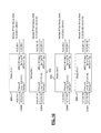
- FIG. 13 is a flowchart of a method for transmitting signals to user devices using the receiving circuit modules.
- module, circuit and/or device refers to an Application-Specific Integrated Circuit (ASIC), an electronic circuit, a processor (shared, dedicated, or group) and memory that executes one or more software or firmware programs, a combinational logic circuit, and/or other suitable components that provide the described functionality.
- ASIC Application-Specific Integrated Circuit
- processor shared, dedicated, or group
- memory that executes one or more software or firmware programs, a combinational logic circuit, and/or other suitable components that provide the described functionality.
- the phrase at least one of A, B, and C should be construed to mean a logical (A or B or C), using a non-exclusive logical OR. It should be understood that steps within a method may be executed in different order without altering the principles of the present disclosure.
- the present disclosure is described with respect to a satellite television system. However, the present disclosure may have various uses including satellite data transmission and reception for home or business uses.
- the system may also be used in a cable system or wireless terrestrial communication system.
- a collection and communication system 10 includes a satellite 12 that includes at least one transponder 13 .
- a satellite 12 that includes at least one transponder 13 .
- multiple transponders are used in a satellite. Although only one satellite is shown, more than one is possible or even likely.
- the collection and communication system 10 includes a central facility or Network Operations Center (NOC) 14 and a plurality of regional or remote uplink facilities (RUF) 16 A, 16 B, 16 C, 16 D, 16 E and 16 F.
- NOC Network Operations Center
- REF regional or remote uplink facilities
- the regional or remote uplink facilities 16 A- 16 F may be located at various locations throughout a landmass 18 such as the continental United States, including more or less locations than those illustrated.
- the regional or remote uplink facilities 16 A- 16 F uplink various uplink signals 17 to satellite 12 .
- the satellite 12 downlinks signals 19 to various users 20 that may be located in different areas of the landmass 18 .
- the users 20 may be mobile or fixed users.
- the uplink signals 17 may be digital signals such as digital television signals or digital data signals.
- the digital television signals may be high-definition television signals, standard-definition signals, or combinations of both. Uplinking may be performed at various frequencies including Ka band. The present disclosure, however, is not limited to Ka band. However, Ka band is a suitable frequency example used throughout this disclosure.
- the central facility or NOC 14 may also receive downlink signals 19 corresponding to the uplink signals 17 from the various regional or remote uplink facilities and from itself for monitoring purposes. The central facility 14 may monitor and control the quality of all the signals broadcast from the system 10 .
- the central facility 14 may also be coupled to the regional or remote uplink facilities through a network such as a computer network having associated communication lines 24 A- 24 F.
- Each communication line 24 A-F is associated with a respective regional or remote uplink site 16 .
- Communication lines 24 A- 24 F are terrestrial-based lines.
- all of the functions performed at the regional or remote uplink facilities may be controlled centrally at the central facility 14 as long as the associated communication lines 24 A-F are not interrupted.
- each regional or remote uplink site 16 A-F may operate autonomously so that uplink signals may continually be provided to the satellite 12 .
- Each of the regional or remote uplink and central facilities includes a transmitting and receiving antenna which is not shown for simplicity in FIG. 1 .
- Each of the regional or remote uplink facilities 16 A- 16 F may also be in communication with a local collection facility collectively referred to with reference numeral 30 .
- a local collection facility collectively referred to with reference numeral 30 .
- three local collection facilities are associated with each remote uplink facility 16 .
- remote uplink facility 16 A has local collection facilities 30 A, 30 B and 30 C associated therewith.
- Local collection facilities 30 D- 30 S are associated with one of the other remote uplink facilities 16 B- 16 F.
- the number of local collection facilities 30 may be numerous, such as 40 for each remote uplink facility.
- the number of local collection facilities 30 is limited by the amount of equipment and the capabilities thereof associated with each remote uplink facility 16 .
- the local collection facilities 30 may be in communication with each remote uplink facility 16 through a communication network 32 .
- the communication network 32 may be an internet protocol (IP) network.
- IP internet protocol
- the signals from the local collection facilities 30 may thus be video-over-IP signals.
- Each of the remote uplink facilities 16 is in communication with each local collection facility 30 through the communication network 32 .
- local collection facility 30 A is in communication with the remote uplink facility 16 A through communication network 32 A
- local collection facility 30 B is in communication with the remote uplink facility 16 A through communication network 32 B, and so on.
- the regional or remote uplink facilities 16 A- 16 F of FIG. 1 are illustrated collectively as reference numeral 16 .
- the regional facilities 16 may actually comprise two facilities that include a primary site 40 (such as the remote uplink facility 16 above) and a diverse site 42 .
- the primary site 40 may be referred to as a primary broadcast center (PBC).
- the central site 14 may also include a primary site and diverse site as is set forth herein.
- the primary site 40 and diverse site 42 of both the central and regional sites may be separated by at least 25 miles or even more such as at least 40 miles. In one constructed embodiment, 50 miles was used.
- the primary site 40 includes a first antenna 44 for transmitting and receiving signals to and from satellite 12 .
- Diverse site 42 also includes an antenna 46 for transmitting and receiving signals from satellite 12 .
- Primary site 40 and diverse site 42 may also receive signals from GPS satellites 50 .
- GPS satellites 50 generate signals corresponding to the location and a precision timed signal that may be provided to the primary site 40 through an antenna 52 and to the diverse site 42 through an antenna 54 .
- redundant GPS antennas ( 52 A- 52 B) for each site may be provided.
- antennas 44 and 46 may also be used to receive GPS signals.
- a precision time source 56 may also be coupled to the primary site 40 and to the diverse site 42 for providing a precision time source.
- the precision time source 56 may include various sources such as coupling to a central atomic clock.
- the precision time source 56 may be used to trigger certain events such as advertising insertions and the like.
- the primary site 40 and the diverse site 42 may be coupled through a communication line 60 .
- Communication line 60 may be a dedicated communication line.
- the primary site 40 and the diverse site 42 may communicate over the communication line using a video over internet protocol (IP).
- IP video over internet protocol
- Various signal sources 64 such as an optical fiber line, copper line or antennas may provide incoming signals 66 to the local collection facility 30 .
- Incoming signal 66 may be television signals.
- the television signals may be over-the-air high-definition signals, over-the-air standard television signals, or high- or standard-definition signals received through a terrestrial communication line.
- the incoming signals 66 such as the television signals may be routed from the local collection facility 30 through the communication network 32 to the primary site 40 , or the diverse site 42 in the event of a switchover.
- the switchover may be manual or a weather-related automatic switchover.
- a manual switchover for example, may be used during a maintenance condition.
- Users 20 receive downlink signals 70 corresponding to the television signals.
- Users 20 may include home-based systems, business-based systems or multiple dwelling unit systems.
- a user 20 has a receiving antenna 72 coupled to an integrated receiver decoder (IRD) 74 that processes the signals and generates audio and video signals corresponding to the received downlink signal 70 for display on the television or monitor 76 .
- IRD integrated receiver decoder
- satellite radio receiving systems may also be used in place of the integrated receiver decoder (IRD) 74 .
- the IRD 74 may be incorporated into or may be referred to as a set top box.
- the system may include multiple users with different types of IRDs 74 capable of decoding signals encoded differently. Some older IRDs may be capable of only decoding MPEG-2 encoded signals. Some newer IRDs may only be able to decode MPEG-4 encoded signals. Some IRDs may be capable of decoding both MPEG-2 and MPEG-4 encoded signals.
- the user 20 may also be a mobile user.
- the user 20 may therefore be implemented in a mobile device or portable device 80 .
- the portable device 80 may include, but is not limited to, various types of devices such as a laptop computer 82 , a personal digital assistant 84 , a cellular telephone 86 or a portable media player 88 .
- the mobile devices may be capable of decoding various types of encoded signals.
- a monitor receiver circuit module 106 may also be coupled to the RF router 102 .
- a back-up receiver circuit module 108 may be included at the local collection facility 30 .
- the receiver circuit modules generally include a receiver module 110 and an encoder module 112 .
- the encoder module 112 may include the capability to produce more than one type of encoded signal.
- the receiver module 110 is used to tune, demodulate and decode the over-the-air signals.
- the decoder may decode from MPEG-2 format.
- the receiver circuit module includes an ATSC receiver.
- the receive signals are processed and encoded into a format such an IP format in the encoder 112 .
- the monitor receiver circuit module is used for generating monitor circuits for each of the receive channel signals. That is, although only one receiver module may be provided, the monitoring system may monitor one of the channel signals. This may be performed remotely through the network 32 from the remote uplink facility 16 .
- the encoder 112 may encode into MPEG-4 format, MPEG-2 format or both MPEG-2 and MPEG-4 formats.
- a serial digital interface router 120 may also be provided.
- the serial digital interface router may be a high-definition serial digital interface router.
- the serial digital interface (SDI) router 120 may receive local feeds directly from the local channel providers. These may be provided through a wire or optical fiber.
- the SDI router 120 routes the channel signals received from the local feeds 118 to the receiving circuit modules 104 A-C, 106 and 108 .
- the output of the receiving circuit modules 104 A-C, 106 and 108 are in communication with a primary router 130 and a back-up router 132 .
- a suitable example of a primary and back-up router is a Cisco® 7604.
- each of the receiving circuit modules 104 , 106 and 108 are in communication with both the primary router 130 and the back-up router 132 .
- An A-B switch 134 is used to generate an output signal corresponding to one of the primary routers 130 or the back-up router 132 .
- the routers 130 , 132 route the IP signals through the switch 134 and through the network 32 which communicates the encoded channel signals to the remote uplink facility 16 , diverse uplink facility and the network operation center.
- the routers 130 , 132 and the switch 134 may be monitored and controlled by the compression system controlled or ABMS system described below.
- the remote uplink facility 16 may include an uplink signal processing system (USPS) 200 .
- USPS uplink signal processing system
- several uplink signal processing systems 200 may be provided. This may include a secondary or back-up USPS that will be referred to as an engineering USPS 200 ′ described in FIG. 4 below.
- the encoded channel signals routed through the network 32 include identification of the signals so that the signals may be properly routed to the proper uplink signal processing system. As described below, this may be done by multicasting.
- the uplink signal processing system 200 generates an output signal to an uplink RF system (URFS) 202 that includes a power amplifier 204 .
- the output signal of each USPS 200 may correspond to one transponder of a satellite.
- the output signal is a multiplexed signal that may include both high-definition television signals and standard-definition television signals.
- the uplink signal processing system 200 may also provide redundant pairs to increase the reliability of the output signal.
- the uplink signal processing system 200 may include a multiplexer 210 , an advance transport processing system (ATPS) 212 , and a modulator 214 . Pairs of multiplexers 210 , advance transport processing systems 212 , and modulators 214 may be provided for redundancy. That is, primary and back-up pairs of each may be provided.
- ATS advance transport processing system
- the multiplexer 210 multiplexes the decoded channel signals from the local area network 32 into a multiplexed transport stream (MPTS).
- the multiplexer 210 may also act to insert advertising into the signal.
- the multiplexer 210 may act as a multiplexing module and as an ad insertion module.
- the multiplexer 210 may be a statistical multiplexer used to group signals from various local collection facilities. Various numbers of encoded channel signals may be multiplexed. In one constructed embodiment, eight channel signals were multiplexed at each multiplexer 210 .
- the multiplexer 210 may receive different signals from different local collection facilities. Each multiplexer 210 may receive all of the signals to be combined for uplink to one transponder of the satellite.
- the advance transport processing system (ATPS) 212 converts the transport stream from the multiplexer 210 into an advanced transport stream such as the DIRECTV® A3 transport stream.
- the ATPS 212 may support either ASI or MPEG-output interface for the broadcast path.
- the ATPS 212 acts as an encryption module.
- the modulators 214 modulate the transport stream from the ATPS 212 and generate an RF signal at a frequency such as an L-band frequency.
- An RF switch 216 is coupled to the primary modulator and back-up modulator 214 .
- the RF switch provides one output signal to the uplink RF system 202 .
- the USPS 200 may also be coupled to a quality control (QC) station console 250 .
- the quality control station console 250 may be coupled directly to the RF switch 216 .
- the quality control station console 250 may also be coupled to a communication monitoring bus 252 .
- the bus 252 may be used to communicate between various components used for monitoring and controlling the various components in the remote uplink facility and the local collection facilities.
- the bus 252 may, for example, be in communication with a technical services monitor console 254 .
- the bus 252 may also be coupled to an advance broadcast management system (ABMS) server 256 . As is illustrated in FIG. 3 , both a primary server and a back-up server 256 are
- a compression system controller 260 may also be coupled to the bus 252 . As is illustrated, both a primary and back-up compression system controller 260 may be provided. The compression system controller 260 may be coupled to a broadcast management system 262 as will be further described below. The ABMS system 256 and the compression system controller 260 may be used to control various functions and monitor various functions of the remote uplink facility and the local collection facilities. These functions will be further described below.
- the compression system controller 260 is a centralized server which is used to control and monitor the receiving circuit modules within the chain of a remote uplink facility.
- the compression system controller 260 may be used to manage, configure, control and monitor the receiving circuit modules and the encoders therein.
- the compression system controller 260 may also control the routers, switches and receivers within the receiving circuit modules.
- the compression system controller may be physically located within the remote uplink facility. However, web access may be provided through a standard web browser for allowing users to interface, configure and control the various systems.
- the compression system controller 260 may be used to initiate a redundancy switch to a back-up receiving circuit module or encoder within the local collection facilities.
- the compression system controller may also be used to initiate a switch to a back-up statistical multiplexer within the remote uplink facility 16 .
- the compression system controller may also be used to update the remote broadcast management system 262 .
- Each of the components of the USPS 200 may be coupled to the bus 252 . That is, the primary and back-up multiplexers 210 , the primary and back-up ATPSs 212 , the primary and back-up modulators 214 , and the RF switch 216 may all be coupled to the bus 252 .
- the ABMS system 256 may be used for various monitoring such as transport level errors, video outages, audio outages, loss of connection from a redundancy controller or a data source, or a compression system controller 260 .
- the remote uplink facility may also include the diverse uplink facility or diverse site 42 .
- the diverse site 42 may receive signals from the primary ATPS 212 in the event of a modulator 214 or switch failure 216 .
- the transport stream signals provided from the primary or back-up advanced transport processing system 212 are communicated to the primary modulator or back-up modulator 214 ′ of the diverse site 42 .
- An RF switch 216 ′ may be used to couple the output of either the primary modulator or the back-up modulator 214 ′ to the uplink RF system 202 .
- the ABMS system 256 ′ may also be used to monitor the output of the diverse uplink facility 256 ′.
- the network operation center 14 may be coupled to the IP network 32 .
- the network operation center 14 may also be coupled to the remote uplink facility 200 through an ATM or IP network 280 .
- the network operation center 14 may have a monitor and control console 282 and a monitoring decoder 284 for monitoring and controlling various functions of the various remote uplink facilities.
- the network operation center monitor and control console 282 may also be used to control and monitor the various local collection facilities 30 . This may be performed directly or through the compression system controller 260 .
- FIG. 4 a system similar to that of FIG. 3 is illustrated. The common components will thus not be described further.
- the system of FIG. 4 illustrates that multiple USPS circuits may be included in the remote facility.
- the multiple USPS circuits are illustrated with the same reference numerals as the USPS chain with primed numbers.
- the functions are the same as the unprinted components.
- the USPSs 200 - 200 ′′ may be referred to as a production USPS.
- the system of FIG. 4 also illustrates an engineering uplink signal processing system 200 ′′.
- the engineering uplink signal processing system 200 ′′ may be coupled to the network 32 and/or the bus 252 .
- the engineering uplink signal processing system 200 ′′ may be at the same location as one of the remote uplink facilities or a different location than the remote uplink facilities.
- the engineering uplink signal processing system 200 ′′ may be used when one of the remote uplink facilities is under maintenance or if an error occurs. Switching to the engineering uplink signal processing system 200 ′′ will be described below.
- the engineering uplink signal processing system 200 ′′ includes a primary and back-up MUX 210 ′′, a primary and back-up ATPS 212 ′′, a primary and back-up modulator 214 ′′ and an RF switch 216 ′′.
- the functioning of each of the components of the USPS is similar to those described above with respect to the production USPS 200 and thus will not be described.
- the output of the RF switch 216 ′′ is communicated to an uplink RF system 202 ′′ that includes an amplifier 204 ′′ for uplinking signals to a satellite.
- a compression system controller 260 ′′ may be in communication with the engineering USPS 200 ′′ through a bus 290 .
- a demodulator 410 is provided.
- the demodulator 410 may be an ATSC demodulator which is illustrated as an 8VSB demodulator 1410 .
- the 8VSB demodulator receives over-the-air television signals from the antenna 100 illustrated in FIGS. 3 and 4 .
- the internal demodulator 410 may support various frequencies including 54 to 863 megahertz with 6 hertz bandwidth channel spacing.
- RF input may be an F-type connector input.
- the demodulated signal from the demodulator 410 is provided to the SV/HD MPEG-2 decoder 412 which may include a downconvertor. That is, if an HD signal is received and a standard-definition signal is desired to be output, the HD signal may be downconverted to an SD signal.
- the output of the decoder may be provided to an MPEG-2 encoder 414 and to a standard-definition/high-definition MPEG-4 encoder 416 .
- the decoded signal from the decoder 412 may be provided to the MPEG-4 encoder 416 through an SD-SDI loop.
- the decoder 412 may provide both HD and SD decoding. For MPEG-2 decoding, horizontal lines of 50 megabits per second may be provided.
- the decoder 412 may pass through the audio from the compressed input source.
- the decoder 412 may also provide selectable letter box cut-out (pan and scan) conversion of 16:9 HD content using 4:3 standard-definition selectable by a central control system.
- the MPEG-2 encoder 414 may provide 480 ⁇ 480 video resolution and may have selectable encoding parameters.
- the MPEG-4 encoder 416 may provide 1080i, 720p and 480i video formats that are user-selectable.
- Both encoders 414 and 416 may have primary and back-up IP outputs and primary and back-up inputs denoted (P) and (B) respectively. Each of the primary inputs/outputs and backup inputs/outputs have addresses to be used in controlling the system.
- the encoders 414 and 416 may generate a variable bit rate output which may be compliant with MPEG-2 specifications. Piecewise, the bit rate may be constant but changes at the program clock reference (PCR).
- a compression system controller 450 may be in communication with the receiving unit 104 . More specifically, the compression controller 450 may be in communication with a host controller 452 which is disposed within the receiving unit 104 .
- the receiving unit 104 may receive configuration signals from the compression system controller 450 . That is, each encoder 414 , 416 may be configured using the compression system controller 450 and host controller 452 . Details of the compression system controlling the encoders 414 and 416 will be further described below.
- the configurations of the encoder and other portions of the receiving unit 104 may be controlled by the compression system controller 450 and the host controller 452 .
- the control may include, but is not limited to, input addresses and output addresses of the primary and backup inputs and outputs of the encoder.
- a first local collection facility LCF 1 , a second local collection facility LCF 2 and a third local collection facility LCF 3 are illustrated in communication with a wide-area network 610 .
- the wide-area network 610 illustrated may be the same network but is broken up for convenience.
- the wide-area network 610 is in communication with a first remote uplink facility RUF 1 , a second remote uplink facility RUF 2 , and a third remote uplink facility RUF 3 .
- Each of the local collection facilities and the remote uplink facilities may be configured in the same or different manners.
- the local collection facility LCF 1 includes three high-definition receiving circuit modules 612 . These may be referred to as receiving units.
- the six high-definition decoder encoders 612 also each include a backup receiving circuit module 614 . Because three high-definition receiving circuit modules 612 are illustrated, three receiving circuit modules 614 are also provided. This relationship is referred to as a one-to-one correspondence between the primary and backup receiving circuit modules. It should be noted that each receiving circuit module and each backup receiving circuit module may include a unique multicast source address and a unique media access control (MAC) address.
- MAC media access control
- a (receiving circuit modules) compression controller 616 may control the primary and backup receiving circuit modules so that at any point in time, only one primary or backup encoder is actively outputting on the active encoder multicast address. The control may be performed by a change signal that causes the address to change.
- the compression controller 616 is in communication with each of the receiving circuit modules 612 / 614 even though the LCF 1 drawing does not depict it (for simplicity).
- both MPEG-4 video and MPEG-2 video are generated from the receiving circuit modules.
- receiving units including a high-definition receiving circuit module 620 are illustrated.
- five high-definition receiving circuit modules are illustrated.
- two standard-definition receiving circuit modules 622 are illustrated.
- the high-definition receiving circuit modules 620 generate both a high-definition MPEG-4 video transport stream and an MPEG-2 video transport stream.
- the standard-definition receiving circuit modules 622 only generate an MPEG-2 video transport stream.
- the backup receiving circuit module 624 may act as a backup receiving circuit module for any of the receiving circuit modules 620 , 622 at the local collection facility regardless of the remote uplink facility receiving the output.
- a compression controller 630 may perform the same function as compression controller 616 .
- each primary receiving circuit module and the backup receiving circuit module have a unique media access control (MAC) address.
- the primary and backup receiving circuit modules may also include a unique multicast destination address for the active encoder in a different unique multicast address destination for the standby encoder within each receiving circuit module.
- the compression controller 630 permits only one encoder as actively outputting a particular transport stream.
- the local collection facility LCF 3 includes high-definition receiving circuit modules 640 .
- the high-definition receiving circuit modules 640 output high-definition signals exclusively. In this example, four high-definition receiving circuit modules are set forth.
- the local collection facility LCF 3 also includes one standard-definition receiving circuit module 642 .
- One backup receiving circuit module 644 is also provided which may be substituted for any of the receiving circuit modules 640 , 642 .
- the compression controller 650 is used to control the receiving circuit modules 640 , 642 and 644 . That is, the address and configuration of the backup encoder 644 may be controlled by the encoder compression controller 650 .
- the first remote uplink facility RUF 1 includes an MPEG-4 multiplexer 660 and a backup multiplexer 662 .
- the MPEG-4 multiplexer merely means it is used to receiving MPEG-4 signals from the local collection facilities LCF 1 - 3 .
- An engineering multiplexer 664 and a backup (BU) engineering multiplexer 666 may also be provided.
- MPEG-4 transports streams from the local collection facility LCF 1 and the local collection facility LCF 2 may be communicated to the MPEG-4 multiplexer 660 or 662 .
- an MPEG-2 multiplexer is not provided in RUF 1 .
- the remote uplink facility RUF 2 may include an MPEG-2 multiplexer 666 and a backup MPEG-2 multiplexer 668 that receive MPEG-2 signals from the local collection facilities.
- the MPEG-2 transport stream signals in this example originate from the local collection facility LCF 1 and LCF 2 .
- the remote uplink facility RUF 3 may include an MPEG-4 multiplexer 670 and a backup MPEG-4 multiplexer 672 .
- the MPEG-4 transport streams provided to the MPEG-4 multiplexers 670 , 672 originate from the second local collection facility LCF 2 and the third local collection facility LCF 3 .
- Each of the multiplexers 660 , 664 , 666 , 668 , 670 and 672 may generate an asynchronous serial interface (ASI) signal.
- ASI asynchronous serial interface
- Each of the remote uplink facilities RUF 1 , RUF 2 , and RUF 3 includes a respective multiplexer compression control system 680 , 682 and 684 .
- the multiplexer compression control systems allow the backup multiplexer to join a multicast stream from an online encoder.
- FIG. 7 another configuration of the system is illustrated.
- four HD receiving circuit modules 710 and one SD receiving circuit module 720 are used for receiving ATSC signals.
- One backup receiving circuit module 722 is also used in the system.
- a compression system controller 723 may be used in a similar manner as described above.
- a wide-area network 724 communicates the signals from the receiving circuit modules to an MPEG-4 multiplexer 726 of a remote uplink facility RUF 4 .
- the MPEG-4 multiplexer 726 may also have a backup multiplexer 728 associated therewith.
- the remote uplink facility RUF 4 may also include encoders for receiving signals directly at the remote uplink facility.
- two HD encoders 730 are provided as well as a backup encoder 732 for use in replacement of the HD encoders 730 .
- An engineering multiplexer 734 may also be included in the remote uplink facility RUF 4 .
- the engineering multiplexer 734 and backup engineering multiplexer 736 may receive signals from a high-definition engineering encoder 740 .
- Two high-definition engineering encoders are illustrated in FIG. 7 .
- a backup engineering encoder 742 may also be used. Both the high-definition engineering encoders and high-definition encoders may be used to receive high-definition serial device interface signals.
- a compression controller 750 may incorporate an encoder compression controller 752 and a multiplexer compression controller 754 .
- the encoder compression controller 752 controls the configuration including the port addresses of the encoders while the multiplexer compression controller 754 controls the operation of the engineering and primary and backup encoders 726 , 728 , 734 and 736 .
- a change signal may be used to change to another address.
- the multiplexers may not only receive signals from a local collection facility but also directly through an encoder. This configuration may also be used with multiple local collection facilities.
- the multiplexer may receive signals from various local collection facilities. Each of the signals for a multiplexer may be combined in a multiplexed stream which is uploaded to a single transponder. That is, each multiplexer may correspond to a single transponder.
- FIG. 8 an example illustrating the IP addresses for a primary encoder 810 , a second primary encoder 812 and a backup encoder 814 is set forth.
- a one-to-N backup encoding scheme is provided. It should be noted that encoders from a one-to-N and a one-to-one backup scheme may be communicated to the same multiplexer. As is illustrated, a single source multicast address will be assigned for each MPEG-2 video output and MPEG-4 video output. A unique destination multicast address will be assigned for each MPEG-2 video and each MPEG-4 video transport stream. The backup encoder will use the primary encoders source and destination multicast address when the backup encoder replaces the primary encoder.
- a backup encoder can be brought online without any changes to the downstream multiplexer.
- the abbreviations MC S and MC D are used in the source end destination multicast IP addresses. These variables are replaced with the appropriate variables for the source and destination when the backup encoder is switched to replace one of the primary encoders.
- the encoders implement a unique IP address and MAC address for the primary connections and a unique IP address and MAC address for the backup connections on each encoder. This allows communication explicitly to either the encoder primary connection or the encoder backup connection.
- Encoders also include a shared virtual IP source address and a shared virtual MAC address that is used for multicast transmission from the encoder. At any one time, the encoder is configured to output from only one of the primary or backup IP ports.
- a change signal may be used to control the ultimate address that is used in the broadcast.
- the change signal may control which output encoder address is used to communicate to the encoder.
- a one-to-one redundant encoder configuration is set forth.
- a first primary encoder 910 and a backup encoder 912 are illustrated.
- another pair including a primary encoder 914 and a corresponding backup encoder 916 is illustrated.
- the control signals from the compression control system are used for configuring the addresses of the encoders.
- a primary multiplexer 1010 and a backup multiplexer 1012 for the primary multiplexer 1010 is illustrated.
- a primary multiplexer 1014 and a backup multiplexer 1016 for the primary multiplexer 1014 is illustrated.
- Each multiplexer has a unique control input IP address.
- the IP addresses are used to control the operation of the primary or backup multiplexer and the addresses thereof.
- the multiplexers also include an IP output and an IP input.
- the IP inputs receive signals from the primary encoders.
- the outputs communicate signals to the transport processing system 212 illustrated in FIG. 3 .
- the control inputs to the multiplexers are in communication with the compression system controller.
- a local collection facility LCF 5 includes high-definition receiving circuit modules 1110 and back-up receiving circuit modules 1111 that communicate high-definition signals through the wide-area network 1112 to a multiplexer 1114 .
- the multiplexer 1114 has a monitoring decoder 1116 coupled thereto that receives the ASI signal.
- a local collection facility LCF 6 includes a plurality of high-definition receiving circuit modules 1120 and a backup receiving circuit module 1122 .
- the wide-area network 1112 communicates the signals from the receiving circuit modules 1120 , 1122 to a multiplexer 1130 or backup multiplexer 1132 .
- the multiplexer 1130 and backup multiplexer 1132 receive MPEG-4 streams.
- An MPEG-2 multiplexer 1134 and backup MPEG-2 multiplexer 1136 receive MPEG-2 signals from the local collection facility LCF 6 .
- a monitoring decoder 1140 is used to monitor the output of the multiplexer and backup multiplexer 1132 .
- a monitoring decoder 1142 is used to monitor the MPEG-2 multiplexer 1134 and the backup MPEG-2 multiplexer 1136 .
- the local collection facility LCF 5 includes a compression system controller 1150 .
- the local collection facility LCF 6 includes a compression system controller 1152 .
- the remote uplink facility RUF 5 may also include a remote uplink facility compression system controller 1154 .
- the MPEG-4 transport stream out of the multiplexer is comprised of the same transport stream which includes the video statistical multiplexer pool, a fixed-rate audio and a fixed-rate video.
- the transport stream may also include a constant bit rate audio and video from a monitoring or engineering encoder.
- the compression system controller 1150 , 1152 may copy the encoder configuration from the online encoder to a backup encoder and then command the encoder to start outputting an MPEG-IP stream without replacing the current online encoder in the multiplexer output statistical multiplexer pool.
- the monitoring decoder may tune to the backup encoder to verify the video content and quality.
- the operator of the system may then command the compression system controller 1150 , 1152 to remove the current online encoder from the output multiplexer and replace it with the backup encoder.
- the monitoring decoder may be able to switch between monitoring an online encoder, monitoring an encoder or monitoring a mirrored encoder by only decoding a different service identifier in the multiplexer output stream.
- a method for configuring an online encoder is set forth.
- a configuration from an online encoder is copied.
- the offline encoder is configured with the online encoder configuration.
- the monitoring decoder is tuned to the backup decoder encoder.
- the operation of the backup decoder encoder is verified by monitoring the quality of the video content and quality of the signal.
- the online encoder may be commanded to an offline status and the offline encoder commanded to an online status. In performing the above functions, the compression controller switches the address of the backup encoder to the address of the output of the online decoder/encoder.
- a channel signal is received.
- the same channel signal is encoded into a first format and in step 1314 the same channel is encoded into a second format.
- the first format may be MPEG-2 encoding and the second format may be MPEG-4 encoding.
- the encoded signals are communicated to one or more uplink sites. It should be noted that the different encoded signals, such as the MPEG-2 signal and the MPEG-4 signal, may be communicated to different remote uplink facilities. This allows greater flexibility in statistically multiplexing the signals.
- the received signals at the multiplexer are multiplexed.
- Different local collection facilities may have signals that are communicated to a multiplexer.
- a multiplexer may have an output that corresponds to one single transponder on one single satellite. Thus, the entire output of one multiplexer corresponds to the input of one transponder of the satellite.
- the encoded and multiplexed signals are ultimately transmitted to user devices.
- various user devices may include standard-definition and/or high-definition signals.
- the various user devices may only be capable of receiving MPEG-2 or MPEG-4 signals.
- any of the receiving units or user devices may receive one of the encoded channel signals.
- the transmission of the signals to a user device may include forming a transport stream in a transport processing system 212 illustrated in FIG. 3 modulating the signal in the modulator 214 of FIG. 3 and communicating the modulated signal to an uplink RF switch 202 illustrated in FIG. 3 .
- the first formatted signal may be communicated to a first multiplexer, and the second formatted signal may be communicated to a second multiplexer.
- the second multiplexer may be located in a different remote uplink facility.
Abstract
Description
Claims (20)
Priority Applications (1)
| Application Number | Priority Date | Filing Date | Title |
|---|---|---|---|
| US13/080,551 US9831971B1 (en) | 2011-04-05 | 2011-04-05 | Method and system for operating a communication system encoded into multiple independently communicated encoding formats |
Applications Claiming Priority (1)
| Application Number | Priority Date | Filing Date | Title |
|---|---|---|---|
| US13/080,551 US9831971B1 (en) | 2011-04-05 | 2011-04-05 | Method and system for operating a communication system encoded into multiple independently communicated encoding formats |
Publications (1)
| Publication Number | Publication Date |
|---|---|
| US9831971B1 true US9831971B1 (en) | 2017-11-28 |
Family
ID=60407692
Family Applications (1)
| Application Number | Title | Priority Date | Filing Date |
|---|---|---|---|
| US13/080,551 Active 2036-09-27 US9831971B1 (en) | 2011-04-05 | 2011-04-05 | Method and system for operating a communication system encoded into multiple independently communicated encoding formats |
Country Status (1)
| Country | Link |
|---|---|
| US (1) | US9831971B1 (en) |
Citations (174)
| Publication number | Priority date | Publication date | Assignee | Title |
|---|---|---|---|---|
| US4317010A (en) | 1978-12-22 | 1982-02-23 | Fillot Jean Jacques Y | Remote monitoring system for remote locating and gain regulating of amplification circuits in data transmission line |
| US4984252A (en) | 1987-11-10 | 1991-01-08 | Nec Corporation | Channel switching system |
| US5189516A (en) | 1990-04-23 | 1993-02-23 | The Grass Valley Group, Inc. | Video preview system for allowing multiple outputs to be viewed simultaneously on the same monitor |
| US5257106A (en) | 1990-08-28 | 1993-10-26 | Sony Corporation | Television signal receiver with memory for storing data on different television system |
| US5323322A (en) | 1992-03-05 | 1994-06-21 | Trimble Navigation Limited | Networked differential GPS system |
| US5327421A (en) | 1992-11-06 | 1994-07-05 | At&T Bell Laboratories | Apparatus for interfacing between telecommunications call signals and broadband signals |
| US5351130A (en) | 1993-01-28 | 1994-09-27 | Houston Satellite Systems, Inc. | Satellite receiver with improved memory back-up and loading capabilities |
| US5452297A (en) | 1993-12-20 | 1995-09-19 | At&T Corp. | Access switches for large ATM networks |
| US5493339A (en) * | 1993-01-21 | 1996-02-20 | Scientific-Atlanta, Inc. | System and method for transmitting a plurality of digital services including compressed imaging services and associated ancillary data services |
| US5499046A (en) | 1994-05-23 | 1996-03-12 | Cable Services Technologies, Inc. | CATV distribution system with each channel having its own remote scheduler |
| US5513180A (en) | 1991-05-14 | 1996-04-30 | Fujitsu Limited | Television signal and ATM cell switching system |
| US5524113A (en) | 1993-08-30 | 1996-06-04 | Washington University | ATM switch interface |
| US5566353A (en) | 1994-09-06 | 1996-10-15 | Bylon Company Limited | Point of purchase video distribution system |
| US5583562A (en) | 1993-12-03 | 1996-12-10 | Scientific-Atlanta, Inc. | System and method for transmitting a plurality of digital services including imaging services |
| US5600573A (en) | 1992-12-09 | 1997-02-04 | Discovery Communications, Inc. | Operations center with video storage for a television program packaging and delivery system |
| US5646675A (en) | 1989-06-22 | 1997-07-08 | Airtrax | System and method for monitoring video program material |
| US5659350A (en) | 1992-12-09 | 1997-08-19 | Discovery Communications, Inc. | Operations center for a television program packaging and delivery system |
| US5666293A (en) | 1994-05-27 | 1997-09-09 | Bell Atlantic Network Services, Inc. | Downloading operating system software through a broadcast channel |
| US5666487A (en) | 1995-06-28 | 1997-09-09 | Bell Atlantic Network Services, Inc. | Network providing signals of different formats to a user by multplexing compressed broadband data with data of a different format into MPEG encoded data stream |
| US5684714A (en) | 1995-05-08 | 1997-11-04 | Kabushiki Kaisha Toshiba | Method and system for a user to manually alter the quality of a previously encoded video sequence |
| US5708961A (en) | 1995-05-01 | 1998-01-13 | Bell Atlantic Network Services, Inc. | Wireless on-premises video distribution using digital multiplexing |
| US5793413A (en) | 1995-05-01 | 1998-08-11 | Bell Atlantic Network Services, Inc. | Wireless video distribution |
| US5926230A (en) | 1995-02-06 | 1999-07-20 | Sony Corporation | Electrical program guide system and method |
| US5930251A (en) | 1996-02-01 | 1999-07-27 | Mitsubishi Denki Kabushiki Kaisha | Multimedia information processing system |
| US5933123A (en) | 1997-12-03 | 1999-08-03 | Kaul-Tronics, Inc. | Combined satellite and terrestrial antenna |
| US5999518A (en) | 1996-12-04 | 1999-12-07 | Alcatel Usa Sourcing, L.P. | Distributed telecommunications switching system and method |
| US6047162A (en) | 1997-09-25 | 2000-04-04 | Com Dev Limited | Regional programming in a direct broadcast satellite |
| US6154772A (en) | 1997-11-04 | 2000-11-28 | Georgia Tech Research Corporation | System and method for the delivery of digital video and data over a communication channel |
| US20010003846A1 (en) | 1999-05-19 | 2001-06-14 | New Horizons Telecasting, Inc. | Encapsulated, streaming media automation and distribution system |
| US6272137B1 (en) | 1997-03-21 | 2001-08-07 | Oki Electric Industry Co., Ltd. | ATM transmission system with subsystems interconnected through reduced number of signal lines |
| US20010026537A1 (en) | 2000-02-24 | 2001-10-04 | Michael Massey | Satellite internet backbone network system using virtual onboard switching |
| US6308286B1 (en) | 1994-06-30 | 2001-10-23 | Hughes Electronics Corporation | Complexity reduction system and method for integrated redundancy switchover systems |
| US20010036198A1 (en) | 1996-09-05 | 2001-11-01 | Hughes Electronics Corporation | Dynamic mapping of broadcast resources |
| US20020007494A1 (en) | 1998-09-28 | 2002-01-17 | Hodge Winston W. | Interactive digital program material encoder and system |
| US20020023165A1 (en) | 2000-01-28 | 2002-02-21 | Lahr Nils B. | Method and apparatus for encoder-based distribution of live video and other streaming content |
| US20020053049A1 (en) | 1997-12-30 | 2002-05-02 | Shoji Shiomoto | Error correction encoding method and apparatus data transmission method receiving method and receiver |
| US20020061023A1 (en) | 1997-05-30 | 2002-05-23 | Masaaki Takizawa | ATM communication terminal and ATM communication system |
| US6401242B1 (en) | 1997-10-24 | 2002-06-04 | General Instrument Corporation | Method and apparatus for designating a preferred source to avoid duplicative programming services |
| US20020105976A1 (en) | 2000-03-10 | 2002-08-08 | Frank Kelly | Method and apparatus for deriving uplink timing from asynchronous traffic across multiple transport streams |
| US20020150061A1 (en) | 1998-08-07 | 2002-10-17 | Hughes Electronics Corporation | Method and apparatus for performing satellite selection in a broadcast communication system |
| US6490273B1 (en) | 1998-08-05 | 2002-12-03 | Sprint Communications Company L.P. | Asynchronous transfer mode architecture migration |
| US20020186320A1 (en) | 2001-06-06 | 2002-12-12 | Carlsgaard Eric Stephen | Video signal processing system with auxiliary information processing capability |
| US20020194596A1 (en) | 2001-06-18 | 2002-12-19 | Srivastava Gopal K. | Control of multiple AV-devices by a single master controller using infrared transmitted commands and bus transmitted commands |
| US20030007564A1 (en) | 2000-06-09 | 2003-01-09 | Cha-Gyun Jeong | Method and devices for digital video signal compression and multi-screen process by multi-thread scaling |
| US6510163B1 (en) | 1997-07-25 | 2003-01-21 | Samsung Electronics Co., Ltd. | Network interface for interfacing PDH network and ATM network |
| US20030018975A1 (en) | 2001-07-18 | 2003-01-23 | Stone Christopher J. | Method and system for wireless audio and video monitoring |
| US20030028897A1 (en) | 2001-08-06 | 2003-02-06 | Brooks Paul D. | Technique for reverse transport of data in a hybrid fiber coax cable system |
| US6529146B1 (en) | 2000-06-09 | 2003-03-04 | Interactive Video Technologies, Inc. | System and method for simultaneously encoding data in multiple formats and at different bit rates |
| US6557031B1 (en) | 1997-09-05 | 2003-04-29 | Hitachi, Ltd. | Transport protocol conversion method and protocol conversion equipment |
| US20030088873A1 (en) | 1997-01-07 | 2003-05-08 | United Video Properties, Inc. | System and method for distributing and broadcasting multimedia |
| US6563955B2 (en) * | 1998-11-13 | 2003-05-13 | Xerox Corporation | Method and apparatus for analyzing image data to use multiple transforms for enhanced image data transmission |
| US20030095554A1 (en) | 2001-11-21 | 2003-05-22 | Nec Corporation | Network transfer system and transfer method |
| WO2003058967A1 (en) | 2001-12-28 | 2003-07-17 | Pegasus Development Corporation | Wideband direct-to-home broadcasting satellite communications system and method |
| US20030140353A1 (en) | 1999-11-08 | 2003-07-24 | Qwest Communications International Inc. | Digital headend and full service network for distribution video and audio programming |
| US20030161262A1 (en) | 2002-02-26 | 2003-08-28 | Nec Corporation | High speed switching router using APS and method for switching the same |
| US6625811B1 (en) | 1997-04-25 | 2003-09-23 | Sony Corporation | Multichannel broadcasting system |
| US20030196211A1 (en) | 2002-04-10 | 2003-10-16 | Peter Chan | Systems, methods and apparatuses for simulated rapid tuning of digital video channels |
| US6654923B1 (en) | 1999-09-09 | 2003-11-25 | Nortel Networks Limited | ATM group protection switching method and apparatus |
| US20040001478A1 (en) | 2002-06-27 | 2004-01-01 | Broadcom Corporation | System and method for isolating network clients |
| US20040022535A1 (en) | 2002-08-01 | 2004-02-05 | Steve Wang | System and method for preventing signal loss in an optical communications network |
| US20040022275A1 (en) | 2002-08-02 | 2004-02-05 | Blanchard Scott D. | Methods and apparatus for coupling an earth terminal to a satellite |
| US6724760B2 (en) | 1997-08-06 | 2004-04-20 | Fujitsu Limited | ATM switch |
| US6724774B1 (en) | 1998-05-18 | 2004-04-20 | Nec Corporation | Subscriber access apparatus capable of adapting all of analog communication access network, ISDN access network and XDSL access network to ATM core network |
| US20040078807A1 (en) | 2002-06-27 | 2004-04-22 | Fries Robert M. | Aggregated EPG manager |
| US6728317B1 (en) * | 1996-01-30 | 2004-04-27 | Dolby Laboratories Licensing Corporation | Moving image compression quality enhancement using displacement filters with negative lobes |
| US6741553B1 (en) | 1999-12-08 | 2004-05-25 | Nortel Networks Limited | Method and system for protecting virtual traffic in a communications network |
| US6751214B1 (en) | 2000-03-30 | 2004-06-15 | Azanda Network Devices, Inc. | Methods and apparatus for dynamically allocating bandwidth between ATM cells and packets |
| US20040117831A1 (en) | 1999-06-28 | 2004-06-17 | United Video Properties, Inc. | Interactive television program guide system and method with niche hubs |
| US20040120349A1 (en) | 2002-11-14 | 2004-06-24 | Hughes Electronics | Systems and methods for transmitting internet protocol data via satellite |
| US6782550B1 (en) | 2000-06-16 | 2004-08-24 | Minerva Networks, Inc. | Program guide with a current-time bar |
| US20040181813A1 (en) | 2003-02-13 | 2004-09-16 | Takaaki Ota | Methods and systems for rapid channel change within a digital system |
| US6795506B1 (en) | 1999-10-05 | 2004-09-21 | Cisco Technology, Inc. | Methods and apparatus for efficient scheduling and multiplexing |
| US6796555B1 (en) | 1999-07-19 | 2004-09-28 | Lucent Technologies Inc. | Centralized video controller for controlling distribution of video signals |
| US20040213247A1 (en) | 2000-09-11 | 2004-10-28 | Takashi Seki | Communication network system and method for synchronously controlling path connection |
| US20040216171A1 (en) | 2001-08-16 | 2004-10-28 | Goldpocket Interactive | Remote monitoring system and method for interactive television data |
| US20040234145A1 (en) | 2003-05-19 | 2004-11-25 | Hitachi, Ltd. | Encoding apparatus, video camera |
| US20040255333A1 (en) | 2001-06-06 | 2004-12-16 | Kevin Kenworthy | Centralized aggregation of broadcast television programming and multi-market digital delivery thereof over interconnected terrestrial fiber optic networks |
| US20050002339A1 (en) | 2003-06-20 | 2005-01-06 | Marconi Communications, Inc. | Distributed protection switching |
| US6873877B1 (en) | 1999-02-11 | 2005-03-29 | Loudeye Corp. | Distributed production system for digitally encoding information |
| US20050076134A1 (en) | 2001-05-17 | 2005-04-07 | Gil Bialik | Apparatus and method for multiple rich media formats video broadcasting |
| US20050086696A1 (en) | 1993-03-29 | 2005-04-21 | Microsoft Corporation | Methods for enabling near video-on-demand and video-on-request services using digital video recorders |
| US20050099969A1 (en) | 1998-04-03 | 2005-05-12 | Roberts Roswell Iii | Satellite receiver/router, system, and method of use |
| US6910078B1 (en) | 2001-11-15 | 2005-06-21 | Cisco Technology, Inc. | Methods and apparatus for controlling the transmission of stream data |
| US20050155079A1 (en) | 2004-01-13 | 2005-07-14 | Zhongming Chen | System and method for managing program assets |
| US20050160477A1 (en) | 2000-08-31 | 2005-07-21 | Kabushiki Kaisha Toshiba | Communication system using home gateway and access server for preventing attacks to home network |
| US20050175085A1 (en) | 2004-01-23 | 2005-08-11 | Sarnoff Corporation | Method and apparatus for providing dentable encoding and encapsulation |
| US20050210133A1 (en) | 2004-03-12 | 2005-09-22 | Danilo Florissi | Method and apparatus for determining monitoring locations in distributed systems |
| US20050210123A1 (en) | 2004-03-20 | 2005-09-22 | Hon Hai Precision Industry Co., Ltd. | System and method for graphically managing network devices |
| US20050240967A1 (en) | 2004-04-27 | 2005-10-27 | Anderson Glen J | System and method for improved channel surfing |
| US6963547B1 (en) | 1998-12-29 | 2005-11-08 | Lg Electronics Inc. | Local multipoint distribution system and ATM data communication method thereof |
| US20060018254A1 (en) | 2004-07-26 | 2006-01-26 | John Sanders | Statistical multiplexer having protective features from extraneous messages generated by redundant system elements |
| US20060035610A1 (en) | 2004-08-13 | 2006-02-16 | Microsoft Corporation | Systems for unifying heterogeneous multimedia tuners |
| US20060050184A1 (en) | 2004-09-09 | 2006-03-09 | General Instrument Corporation | Hot/cold swappable consumer based tuner/demod/fec module |
| US20060064726A1 (en) | 2004-09-21 | 2006-03-23 | Loner Patrick J | Method of using feedback from consumer terminals to adaptively control a satellite system |
| US20060083315A1 (en) | 2004-10-15 | 2006-04-20 | Hitachi, Ltd. | Digital broadcast sending apparatus, receiving apparatus and digital broadcast system |
| US20060085834A1 (en) | 2004-10-19 | 2006-04-20 | Cayin Technology Co., Ltd. | System and method for transmitting multi-channel signals |
| US7039937B1 (en) | 2001-02-28 | 2006-05-02 | Glenn R Bryce | System and method for providing satellite signals to multiple receiving units |
| US7039116B1 (en) | 2000-11-07 | 2006-05-02 | Cisco Technology, Inc. | Methods and apparatus for embedding and format conversion of compressed video data |
| US20060098735A1 (en) | 2004-11-10 | 2006-05-11 | Yu-Chung Chang | Apparatus for motion estimation using a two-dimensional processing element array and method therefor |
| US20060126634A1 (en) | 2004-10-06 | 2006-06-15 | Samsung Electronics Co., Ltd. | Method and apparatus of providing and receiving video services in digital audio broadcasting (DAB) system |
| US7072365B1 (en) | 2000-12-29 | 2006-07-04 | Arris Interactive, Llc | System and method for multiplexing broadband signals |
| US7080398B1 (en) | 1999-11-30 | 2006-07-18 | Agilent Technologies, Inc. | Monitoring system and method implementing warning interface logic |
| US20060166699A1 (en) | 2005-01-21 | 2006-07-27 | King's College London | Method of discovering multi-mode mobile terminals |
| US20060198389A1 (en) | 2005-03-01 | 2006-09-07 | Eriokson Michael J | Multi-drop ethernet |
| US20060242674A1 (en) | 2005-04-22 | 2006-10-26 | Medford Brad A | Methods and apparatus to broadcast advanced television system committee video in switched digital video systems |
| US20070002851A1 (en) | 2005-06-30 | 2007-01-04 | Toni Paila | Transmission and reception of session packets |
| US20070022438A1 (en) | 2005-07-22 | 2007-01-25 | Marc Arseneau | System and Methods for Perfoming Online Purchase of Delivery of Service to a Handheld Device |
| US20070040933A1 (en) | 2005-07-22 | 2007-02-22 | Aircode Co., Ltd. | Transport stream reprocessing device and data broadcasting system using the device |
| US20070053379A1 (en) | 2005-09-06 | 2007-03-08 | Mark Hershey | Streaming media encoder with confidence monitor |
| US20070079351A1 (en) | 2000-12-11 | 2007-04-05 | Wang Jason N | System and method for balancing video encoding tasks between multiple processors |
| US7209636B2 (en) | 1997-09-25 | 2007-04-24 | Sony Corporation | Encoded stream generating apparatus and method, data transmission system and method, and editing system and method |
| US20070094691A1 (en) | 2005-10-24 | 2007-04-26 | Gazdzinski Robert F | Method and apparatus for on-demand content transmission and control over networks |
| US20070091857A1 (en) | 2005-10-24 | 2007-04-26 | General Instrument Corporation | Method and apparatus for generating multiplexed signals |
| US7212738B1 (en) | 2002-08-01 | 2007-05-01 | Finisar Corporation | Preventing signal loss in an optical communications network |
| US7219367B2 (en) | 2002-09-09 | 2007-05-15 | Scientific-Atlanta, Inc. | Backup communication modes |
| US20070118861A1 (en) | 2005-11-21 | 2007-05-24 | General Instrument Corporation | System and method for delivering graphics received through a cable television system to a digital television |
| US7224837B2 (en) | 2000-10-11 | 2007-05-29 | Screenpeaks Ltd. | Digital video broadcasting |
| US20070121189A1 (en) * | 2005-11-17 | 2007-05-31 | Alcatel | Data transmission devices for communication facilities of a passive optical network |
| US20070136765A1 (en) | 2005-12-13 | 2007-06-14 | The Directv Group, Inc. | Multiple dwelling unit satellite television delivery system |
| US20070136777A1 (en) | 2005-12-09 | 2007-06-14 | Charles Hasek | Caption data delivery apparatus and methods |
| US20070157281A1 (en) | 2005-12-23 | 2007-07-05 | United Video Properties, Inc. | Interactive media guidance system having multiple devices |
| US20070162927A1 (en) | 2004-07-23 | 2007-07-12 | Arun Ramaswamy | Methods and apparatus for monitoring the insertion of local media content into a program stream |
| US20070186251A1 (en) | 2006-02-03 | 2007-08-09 | Horowitz Edward D | Emergency satellite network |
| US20070204300A1 (en) | 2006-02-27 | 2007-08-30 | Markley Jeffrey P | Methods and apparatus for selecting digital interface technology for programming and data delivery |
| US20070204311A1 (en) | 2006-02-27 | 2007-08-30 | Hasek Charles A | Methods and apparatus for selecting digital coding/decoding technology for programming and data delivery |
| US7266133B2 (en) * | 2002-11-13 | 2007-09-04 | General Instrument Corporation | Methods and apparatus for statistical multiplexing with distributed multiplexers |
| US20070261073A1 (en) | 2006-04-25 | 2007-11-08 | Xorbit, Inc. | System and method for monitoring video data |
| US20070263627A1 (en) | 2001-01-26 | 2007-11-15 | Nec Corporation | Method and system for controlling communication network and router used in the network |
| US20070268817A1 (en) | 2006-05-22 | 2007-11-22 | Nortel Networks Limited | Method and system for protecting a sub-domain within a broadcast domain |
| US7302224B2 (en) | 2000-05-03 | 2007-11-27 | The Directv Group, Inc. | Communication system for rebroadcasting electronic content within local area network |
| US20070291713A1 (en) | 2006-06-20 | 2007-12-20 | Fujitsu Limited | Communication system |
| US7315887B1 (en) | 2001-04-11 | 2008-01-01 | Alcatel Lucent | Facilitating integration of communications network equipment inventory management |
| US7330509B2 (en) * | 2003-09-12 | 2008-02-12 | International Business Machines Corporation | Method for video transcoding with adaptive frame rate control |
| US7333425B2 (en) | 2002-11-19 | 2008-02-19 | Alcatel | Failure localization in a transmission network |
| US20080066096A1 (en) | 2006-08-24 | 2008-03-13 | Sbc Knowledge Ventures L.P. | Method and apparatus for sending stored advertising data from an internet protocol television end user network interface device |
| US7346918B2 (en) | 2000-12-27 | 2008-03-18 | Z-Band, Inc. | Intelligent device system and method for distribution of digital signals on a wideband signal distribution system |
| US20080069155A1 (en) | 2006-09-14 | 2008-03-20 | Tandberg Television Inc. | Systems and methods for analog channel reuse in a cable system |
| US20080101455A1 (en) | 2006-10-25 | 2008-05-01 | Digital Deck, Inc. | Apparatus and method for multiple format encoding |
| US20080102750A1 (en) | 2006-11-01 | 2008-05-01 | Keener David J | Broadcast method and system |
| US20080137543A1 (en) | 2006-12-12 | 2008-06-12 | Cisco Technology, Inc. | Remote testing of an electronic device via network connection |
| US20080201748A1 (en) | 2006-02-27 | 2008-08-21 | Hasek Charles A | Methods and apparatus for device capabilities discovery and utilization within a content-based network |
| US20080282011A1 (en) | 2007-05-09 | 2008-11-13 | Arcadyan Technology Corporation | Remote control system and method thereof |
| US20080291907A1 (en) | 2004-06-14 | 2008-11-27 | Siemens Aktiengesellschaft | Data-Transmission Device and Method for Transmitting Data with a Reduced Outage Risk |
| US7460832B2 (en) | 2004-04-12 | 2008-12-02 | The Directv Group, Inc. | Methods and apparatuses for minimizing co-channel interference |
| US20090022241A1 (en) | 2005-01-21 | 2009-01-22 | Matsushita Electric Industrial Co., Ltd. | Wireless communication apparatus and wireless communication method |
| US20090025027A1 (en) | 2007-07-20 | 2009-01-22 | Michael Craner | Systems & methods for allocating bandwidth in switched digital video systems based on interest |
| US7493648B2 (en) | 2000-04-11 | 2009-02-17 | Sony Corporation | Data transmission device, data receiving device, data transmitting method, data receiving method, recording device, playback device, recording method, and playback method |
| US20090052323A1 (en) | 2005-03-21 | 2009-02-26 | Dirk Breynaert | Managing Traffic in a Satellite Transmission System |
| US20090070825A1 (en) | 2007-09-11 | 2009-03-12 | The Directv Group, Inc. | Method and System for Monitoring and Controlling Receiving Circuit Modules at a Local Collection Facility From a Remote Facility |
| US20090067490A1 (en) | 2007-09-11 | 2009-03-12 | The Directv Group, Inc. | Method and system for monitoring and switching between a primary encoder and a back-up encoder in a communication system |
| US20090067365A1 (en) | 2007-09-11 | 2009-03-12 | The Directv Group, Inc. | Method and System for Switching to an Engineering Signal Processing System from a Production Signal Processing System |
| US20090069021A1 (en) | 2007-09-11 | 2009-03-12 | The Directv Group, Inc. | Method and System for Monitoring and Switching Between a First Uplink Signal Processing Circuit and a Second Uplink Signal Processing Circuit |
| US20090070824A1 (en) | 2007-09-11 | 2009-03-12 | The Directv Group, Inc. | Method and System for Monitoring and Switching Between Primary and Back-up Uplink Signal Processing Circuits in a Satellite Communication System |
| US20090070846A1 (en) | 2007-09-12 | 2009-03-12 | The Directv Group, Inc. | Method and system for monitoring and controlling a local collection facility from a remote facility using an asynchronous transfer mode (atm) network |
| US20090067433A1 (en) | 2007-09-12 | 2009-03-12 | The Directv Group, Inc. | Method and system for controlling a back-up network adapter in a local collection facility from a remote facility |
| US20090070830A1 (en) * | 2007-09-11 | 2009-03-12 | The Directv Group, Inc. | Method and System for Monitoring a Receiving Circuit Module and Controlling Switching to a Back-up Receiving Circuit Module at a Local Collection Facility from a Remote Facility |
| US20090067432A1 (en) | 2007-09-12 | 2009-03-12 | The Directv Group, Inc. | Method and system for controlling a back-up multiplexer in a local collection facility from a remote facility |
| US20090066848A1 (en) * | 2007-09-12 | 2009-03-12 | The Directv Group, Inc. | Method and system for controlling a back-up receiver and encoder in a local collection facility from a remote facility |
| US7525993B2 (en) | 2006-05-24 | 2009-04-28 | Newport Media, Inc. | Robust transmission system and method for mobile television applications |
| US20090109883A1 (en) | 2007-10-31 | 2009-04-30 | Wasden Mitchell B | Method and system for monitoring and encoding signals in a local facility and communicating the signals between a local collection facility and a remote facility using an ip network |
| US20090113490A1 (en) | 2007-10-30 | 2009-04-30 | Wasden Mitchell B | Method and system for monitoring and controlling a local collection facility from a remote facility through an ip network |
| US20090110052A1 (en) | 2007-10-30 | 2009-04-30 | Wasden Mitchell B | Method and system for monitoring and controlling a back-up receiver in local collection facility from a remote facility using an ip network |
| US20090109836A1 (en) | 2007-10-31 | 2009-04-30 | Wasden Mitchell B | Method and system for controlling redundancy of individual components of a remote facility system |
| US7529276B1 (en) | 2002-09-03 | 2009-05-05 | Cisco Technology, Inc. | Combined jitter and multiplexing systems and methods |
| US20090213814A1 (en) | 2003-08-20 | 2009-08-27 | Samsung Electronics Co., Ltd. | Method and apparatus for providing uplink packet data service in asynchronous wcdma system |
| US7596350B1 (en) | 2006-09-29 | 2009-09-29 | The Directv Group, Inc. | Method and system for determining delays between a primary site and diverse site in a satellite communication system |
| US7602846B1 (en) * | 2003-08-01 | 2009-10-13 | Cisco Technology, Inc. | Efficiently distributing video using a hybrid network that uses existing infrastructure |
| US7607154B2 (en) | 2002-10-04 | 2009-10-20 | Rai Radiotelevisione Italiana S.P.A. | System for the transmission of DVB/MPEG digital signals, particularly for satellite communication |
| US7650620B2 (en) | 1998-03-06 | 2010-01-19 | Laurence A Fish | Method and apparatus for push and pull distribution of multimedia |
| US7746791B2 (en) | 2005-08-24 | 2010-06-29 | Abb Technology Ag | Monitoring an industrial communication network |
| US20100208595A1 (en) | 2007-10-09 | 2010-08-19 | Wei Zhao | Arrangement and a method for handling failures in a network |
| US7835596B2 (en) * | 2003-12-16 | 2010-11-16 | International Business Machines Corporation | Componentized application sharing |
| US8139517B2 (en) | 2005-10-14 | 2012-03-20 | Thomson Licensing | Method of generating and demultiplexing an optimized contribution signal, and regionalized data broadcasting system |
| US8170069B2 (en) * | 2007-09-11 | 2012-05-01 | The Directv Group, Inc. | Method and system for processing signals from a local collection facility at a signal processing facility |
-
2011
- 2011-04-05 US US13/080,551 patent/US9831971B1/en active Active
Patent Citations (187)
| Publication number | Priority date | Publication date | Assignee | Title |
|---|---|---|---|---|
| US4317010A (en) | 1978-12-22 | 1982-02-23 | Fillot Jean Jacques Y | Remote monitoring system for remote locating and gain regulating of amplification circuits in data transmission line |
| US4984252A (en) | 1987-11-10 | 1991-01-08 | Nec Corporation | Channel switching system |
| US5155483A (en) | 1987-11-10 | 1992-10-13 | Nec Corporation | Channel switching system |
| US5646675A (en) | 1989-06-22 | 1997-07-08 | Airtrax | System and method for monitoring video program material |
| US5189516A (en) | 1990-04-23 | 1993-02-23 | The Grass Valley Group, Inc. | Video preview system for allowing multiple outputs to be viewed simultaneously on the same monitor |
| US5257106A (en) | 1990-08-28 | 1993-10-26 | Sony Corporation | Television signal receiver with memory for storing data on different television system |
| US5513180A (en) | 1991-05-14 | 1996-04-30 | Fujitsu Limited | Television signal and ATM cell switching system |
| US5323322A (en) | 1992-03-05 | 1994-06-21 | Trimble Navigation Limited | Networked differential GPS system |
| US5327421A (en) | 1992-11-06 | 1994-07-05 | At&T Bell Laboratories | Apparatus for interfacing between telecommunications call signals and broadband signals |
| US5600573A (en) | 1992-12-09 | 1997-02-04 | Discovery Communications, Inc. | Operations center with video storage for a television program packaging and delivery system |
| US5659350A (en) | 1992-12-09 | 1997-08-19 | Discovery Communications, Inc. | Operations center for a television program packaging and delivery system |
| US20090254962A1 (en) | 1992-12-09 | 2009-10-08 | Comcast Ip Holdings I, Llc | Operations center for a television program packaging and delivery system |
| US5493339A (en) * | 1993-01-21 | 1996-02-20 | Scientific-Atlanta, Inc. | System and method for transmitting a plurality of digital services including compressed imaging services and associated ancillary data services |
| US5351130A (en) | 1993-01-28 | 1994-09-27 | Houston Satellite Systems, Inc. | Satellite receiver with improved memory back-up and loading capabilities |
| US20050086696A1 (en) | 1993-03-29 | 2005-04-21 | Microsoft Corporation | Methods for enabling near video-on-demand and video-on-request services using digital video recorders |
| US5524113A (en) | 1993-08-30 | 1996-06-04 | Washington University | ATM switch interface |
| US5583562A (en) | 1993-12-03 | 1996-12-10 | Scientific-Atlanta, Inc. | System and method for transmitting a plurality of digital services including imaging services |
| US5452297A (en) | 1993-12-20 | 1995-09-19 | At&T Corp. | Access switches for large ATM networks |
| US5499046A (en) | 1994-05-23 | 1996-03-12 | Cable Services Technologies, Inc. | CATV distribution system with each channel having its own remote scheduler |
| US5666293A (en) | 1994-05-27 | 1997-09-09 | Bell Atlantic Network Services, Inc. | Downloading operating system software through a broadcast channel |
| US6308286B1 (en) | 1994-06-30 | 2001-10-23 | Hughes Electronics Corporation | Complexity reduction system and method for integrated redundancy switchover systems |
| US5566353A (en) | 1994-09-06 | 1996-10-15 | Bylon Company Limited | Point of purchase video distribution system |
| US5926230A (en) | 1995-02-06 | 1999-07-20 | Sony Corporation | Electrical program guide system and method |
| US5793413A (en) | 1995-05-01 | 1998-08-11 | Bell Atlantic Network Services, Inc. | Wireless video distribution |
| US5708961A (en) | 1995-05-01 | 1998-01-13 | Bell Atlantic Network Services, Inc. | Wireless on-premises video distribution using digital multiplexing |
| US5684714A (en) | 1995-05-08 | 1997-11-04 | Kabushiki Kaisha Toshiba | Method and system for a user to manually alter the quality of a previously encoded video sequence |
| US5666487A (en) | 1995-06-28 | 1997-09-09 | Bell Atlantic Network Services, Inc. | Network providing signals of different formats to a user by multplexing compressed broadband data with data of a different format into MPEG encoded data stream |
| US6728317B1 (en) * | 1996-01-30 | 2004-04-27 | Dolby Laboratories Licensing Corporation | Moving image compression quality enhancement using displacement filters with negative lobes |
| US5930251A (en) | 1996-02-01 | 1999-07-27 | Mitsubishi Denki Kabushiki Kaisha | Multimedia information processing system |
| US20010036198A1 (en) | 1996-09-05 | 2001-11-01 | Hughes Electronics Corporation | Dynamic mapping of broadcast resources |
| US5999518A (en) | 1996-12-04 | 1999-12-07 | Alcatel Usa Sourcing, L.P. | Distributed telecommunications switching system and method |
| US20030088873A1 (en) | 1997-01-07 | 2003-05-08 | United Video Properties, Inc. | System and method for distributing and broadcasting multimedia |
| US6272137B1 (en) | 1997-03-21 | 2001-08-07 | Oki Electric Industry Co., Ltd. | ATM transmission system with subsystems interconnected through reduced number of signal lines |
| US6625811B1 (en) | 1997-04-25 | 2003-09-23 | Sony Corporation | Multichannel broadcasting system |
| US20020061023A1 (en) | 1997-05-30 | 2002-05-23 | Masaaki Takizawa | ATM communication terminal and ATM communication system |
| US6496522B1 (en) | 1997-05-30 | 2002-12-17 | Hitachi, Ltd. | ATM communication terminal and ATM communication system |
| US6510163B1 (en) | 1997-07-25 | 2003-01-21 | Samsung Electronics Co., Ltd. | Network interface for interfacing PDH network and ATM network |
| US6724760B2 (en) | 1997-08-06 | 2004-04-20 | Fujitsu Limited | ATM switch |
| US6557031B1 (en) | 1997-09-05 | 2003-04-29 | Hitachi, Ltd. | Transport protocol conversion method and protocol conversion equipment |
| US7209636B2 (en) | 1997-09-25 | 2007-04-24 | Sony Corporation | Encoded stream generating apparatus and method, data transmission system and method, and editing system and method |
| US6047162A (en) | 1997-09-25 | 2000-04-04 | Com Dev Limited | Regional programming in a direct broadcast satellite |
| US6401242B1 (en) | 1997-10-24 | 2002-06-04 | General Instrument Corporation | Method and apparatus for designating a preferred source to avoid duplicative programming services |
| US6434562B1 (en) | 1997-11-04 | 2002-08-13 | Georgia Tech Research Corporation | Computer system and method for providing digital video and data over a communication channel |
| US6154772A (en) | 1997-11-04 | 2000-11-28 | Georgia Tech Research Corporation | System and method for the delivery of digital video and data over a communication channel |
| US5933123A (en) | 1997-12-03 | 1999-08-03 | Kaul-Tronics, Inc. | Combined satellite and terrestrial antenna |
| US20020053049A1 (en) | 1997-12-30 | 2002-05-02 | Shoji Shiomoto | Error correction encoding method and apparatus data transmission method receiving method and receiver |
| US7650620B2 (en) | 1998-03-06 | 2010-01-19 | Laurence A Fish | Method and apparatus for push and pull distribution of multimedia |
| US20050099969A1 (en) | 1998-04-03 | 2005-05-12 | Roberts Roswell Iii | Satellite receiver/router, system, and method of use |
| US6724774B1 (en) | 1998-05-18 | 2004-04-20 | Nec Corporation | Subscriber access apparatus capable of adapting all of analog communication access network, ISDN access network and XDSL access network to ATM core network |
| US6490273B1 (en) | 1998-08-05 | 2002-12-03 | Sprint Communications Company L.P. | Asynchronous transfer mode architecture migration |
| US20020150061A1 (en) | 1998-08-07 | 2002-10-17 | Hughes Electronics Corporation | Method and apparatus for performing satellite selection in a broadcast communication system |
| US20020007494A1 (en) | 1998-09-28 | 2002-01-17 | Hodge Winston W. | Interactive digital program material encoder and system |
| US6563955B2 (en) * | 1998-11-13 | 2003-05-13 | Xerox Corporation | Method and apparatus for analyzing image data to use multiple transforms for enhanced image data transmission |
| US6963547B1 (en) | 1998-12-29 | 2005-11-08 | Lg Electronics Inc. | Local multipoint distribution system and ATM data communication method thereof |
| US6873877B1 (en) | 1999-02-11 | 2005-03-29 | Loudeye Corp. | Distributed production system for digitally encoding information |
| US20010003846A1 (en) | 1999-05-19 | 2001-06-14 | New Horizons Telecasting, Inc. | Encapsulated, streaming media automation and distribution system |
| US20040117831A1 (en) | 1999-06-28 | 2004-06-17 | United Video Properties, Inc. | Interactive television program guide system and method with niche hubs |
| US6796555B1 (en) | 1999-07-19 | 2004-09-28 | Lucent Technologies Inc. | Centralized video controller for controlling distribution of video signals |
| US6654923B1 (en) | 1999-09-09 | 2003-11-25 | Nortel Networks Limited | ATM group protection switching method and apparatus |
| US6795506B1 (en) | 1999-10-05 | 2004-09-21 | Cisco Technology, Inc. | Methods and apparatus for efficient scheduling and multiplexing |
| US20030140353A1 (en) | 1999-11-08 | 2003-07-24 | Qwest Communications International Inc. | Digital headend and full service network for distribution video and audio programming |
| US7080398B1 (en) | 1999-11-30 | 2006-07-18 | Agilent Technologies, Inc. | Monitoring system and method implementing warning interface logic |
| US6741553B1 (en) | 1999-12-08 | 2004-05-25 | Nortel Networks Limited | Method and system for protecting virtual traffic in a communications network |
| US20020023165A1 (en) | 2000-01-28 | 2002-02-21 | Lahr Nils B. | Method and apparatus for encoder-based distribution of live video and other streaming content |
| US20010026537A1 (en) | 2000-02-24 | 2001-10-04 | Michael Massey | Satellite internet backbone network system using virtual onboard switching |
| US20020105976A1 (en) | 2000-03-10 | 2002-08-08 | Frank Kelly | Method and apparatus for deriving uplink timing from asynchronous traffic across multiple transport streams |
| US6751214B1 (en) | 2000-03-30 | 2004-06-15 | Azanda Network Devices, Inc. | Methods and apparatus for dynamically allocating bandwidth between ATM cells and packets |
| US7493648B2 (en) | 2000-04-11 | 2009-02-17 | Sony Corporation | Data transmission device, data receiving device, data transmitting method, data receiving method, recording device, playback device, recording method, and playback method |
| US7302224B2 (en) | 2000-05-03 | 2007-11-27 | The Directv Group, Inc. | Communication system for rebroadcasting electronic content within local area network |
| US6529146B1 (en) | 2000-06-09 | 2003-03-04 | Interactive Video Technologies, Inc. | System and method for simultaneously encoding data in multiple formats and at different bit rates |
| US20030007564A1 (en) | 2000-06-09 | 2003-01-09 | Cha-Gyun Jeong | Method and devices for digital video signal compression and multi-screen process by multi-thread scaling |
| US6782550B1 (en) | 2000-06-16 | 2004-08-24 | Minerva Networks, Inc. | Program guide with a current-time bar |
| US20050160477A1 (en) | 2000-08-31 | 2005-07-21 | Kabushiki Kaisha Toshiba | Communication system using home gateway and access server for preventing attacks to home network |
| US20040213247A1 (en) | 2000-09-11 | 2004-10-28 | Takashi Seki | Communication network system and method for synchronously controlling path connection |
| US7224837B2 (en) | 2000-10-11 | 2007-05-29 | Screenpeaks Ltd. | Digital video broadcasting |
| US7039116B1 (en) | 2000-11-07 | 2006-05-02 | Cisco Technology, Inc. | Methods and apparatus for embedding and format conversion of compressed video data |
| US20070079351A1 (en) | 2000-12-11 | 2007-04-05 | Wang Jason N | System and method for balancing video encoding tasks between multiple processors |
| US7346918B2 (en) | 2000-12-27 | 2008-03-18 | Z-Band, Inc. | Intelligent device system and method for distribution of digital signals on a wideband signal distribution system |
| US7072365B1 (en) | 2000-12-29 | 2006-07-04 | Arris Interactive, Llc | System and method for multiplexing broadband signals |
| US20070263627A1 (en) | 2001-01-26 | 2007-11-15 | Nec Corporation | Method and system for controlling communication network and router used in the network |
| US7039937B1 (en) | 2001-02-28 | 2006-05-02 | Glenn R Bryce | System and method for providing satellite signals to multiple receiving units |
| US7315887B1 (en) | 2001-04-11 | 2008-01-01 | Alcatel Lucent | Facilitating integration of communications network equipment inventory management |
| US20050076134A1 (en) | 2001-05-17 | 2005-04-07 | Gil Bialik | Apparatus and method for multiple rich media formats video broadcasting |
| US20020186320A1 (en) | 2001-06-06 | 2002-12-12 | Carlsgaard Eric Stephen | Video signal processing system with auxiliary information processing capability |
| US20040255333A1 (en) | 2001-06-06 | 2004-12-16 | Kevin Kenworthy | Centralized aggregation of broadcast television programming and multi-market digital delivery thereof over interconnected terrestrial fiber optic networks |
| US20020194596A1 (en) | 2001-06-18 | 2002-12-19 | Srivastava Gopal K. | Control of multiple AV-devices by a single master controller using infrared transmitted commands and bus transmitted commands |
| US20030018975A1 (en) | 2001-07-18 | 2003-01-23 | Stone Christopher J. | Method and system for wireless audio and video monitoring |
| US20030028897A1 (en) | 2001-08-06 | 2003-02-06 | Brooks Paul D. | Technique for reverse transport of data in a hybrid fiber coax cable system |
| US20040216171A1 (en) | 2001-08-16 | 2004-10-28 | Goldpocket Interactive | Remote monitoring system and method for interactive television data |
| US6910078B1 (en) | 2001-11-15 | 2005-06-21 | Cisco Technology, Inc. | Methods and apparatus for controlling the transmission of stream data |
| US20030095554A1 (en) | 2001-11-21 | 2003-05-22 | Nec Corporation | Network transfer system and transfer method |
| US20100023972A1 (en) * | 2001-12-28 | 2010-01-28 | Summers Macy W | Wideband direct-to-home broadcasting satellite communications system and method |
| US7587736B2 (en) * | 2001-12-28 | 2009-09-08 | Xanadoo Company | Wideband direct-to-home broadcasting satellite communications system and method |
| US20030217362A1 (en) | 2001-12-28 | 2003-11-20 | Summers Macy W. | Wideband direct-to-home broadcasting satellite communications system and method |
| WO2003058967A1 (en) | 2001-12-28 | 2003-07-17 | Pegasus Development Corporation | Wideband direct-to-home broadcasting satellite communications system and method |
| US20030161262A1 (en) | 2002-02-26 | 2003-08-28 | Nec Corporation | High speed switching router using APS and method for switching the same |
| US20030196211A1 (en) | 2002-04-10 | 2003-10-16 | Peter Chan | Systems, methods and apparatuses for simulated rapid tuning of digital video channels |
| US20040078807A1 (en) | 2002-06-27 | 2004-04-22 | Fries Robert M. | Aggregated EPG manager |
| US20040001478A1 (en) | 2002-06-27 | 2004-01-01 | Broadcom Corporation | System and method for isolating network clients |
| US7212738B1 (en) | 2002-08-01 | 2007-05-01 | Finisar Corporation | Preventing signal loss in an optical communications network |
| US20040022535A1 (en) | 2002-08-01 | 2004-02-05 | Steve Wang | System and method for preventing signal loss in an optical communications network |
| US20040022275A1 (en) | 2002-08-02 | 2004-02-05 | Blanchard Scott D. | Methods and apparatus for coupling an earth terminal to a satellite |
| US7529276B1 (en) | 2002-09-03 | 2009-05-05 | Cisco Technology, Inc. | Combined jitter and multiplexing systems and methods |
| US7219367B2 (en) | 2002-09-09 | 2007-05-15 | Scientific-Atlanta, Inc. | Backup communication modes |
| US7607154B2 (en) | 2002-10-04 | 2009-10-20 | Rai Radiotelevisione Italiana S.P.A. | System for the transmission of DVB/MPEG digital signals, particularly for satellite communication |
| US7266133B2 (en) * | 2002-11-13 | 2007-09-04 | General Instrument Corporation | Methods and apparatus for statistical multiplexing with distributed multiplexers |
| US20040120349A1 (en) | 2002-11-14 | 2004-06-24 | Hughes Electronics | Systems and methods for transmitting internet protocol data via satellite |
| US7333425B2 (en) | 2002-11-19 | 2008-02-19 | Alcatel | Failure localization in a transmission network |
| US20040181813A1 (en) | 2003-02-13 | 2004-09-16 | Takaaki Ota | Methods and systems for rapid channel change within a digital system |
| US7317837B2 (en) * | 2003-05-19 | 2008-01-08 | Hitachi, Ltd. | Encoding apparatus, video camera |
| US20040234145A1 (en) | 2003-05-19 | 2004-11-25 | Hitachi, Ltd. | Encoding apparatus, video camera |
| US20050002339A1 (en) | 2003-06-20 | 2005-01-06 | Marconi Communications, Inc. | Distributed protection switching |
| US7602846B1 (en) * | 2003-08-01 | 2009-10-13 | Cisco Technology, Inc. | Efficiently distributing video using a hybrid network that uses existing infrastructure |
| US20090213814A1 (en) | 2003-08-20 | 2009-08-27 | Samsung Electronics Co., Ltd. | Method and apparatus for providing uplink packet data service in asynchronous wcdma system |
| US7330509B2 (en) * | 2003-09-12 | 2008-02-12 | International Business Machines Corporation | Method for video transcoding with adaptive frame rate control |
| US7835596B2 (en) * | 2003-12-16 | 2010-11-16 | International Business Machines Corporation | Componentized application sharing |
| US20050155079A1 (en) | 2004-01-13 | 2005-07-14 | Zhongming Chen | System and method for managing program assets |
| US20050175085A1 (en) | 2004-01-23 | 2005-08-11 | Sarnoff Corporation | Method and apparatus for providing dentable encoding and encapsulation |
| US20050210133A1 (en) | 2004-03-12 | 2005-09-22 | Danilo Florissi | Method and apparatus for determining monitoring locations in distributed systems |
| US20050210123A1 (en) | 2004-03-20 | 2005-09-22 | Hon Hai Precision Industry Co., Ltd. | System and method for graphically managing network devices |
| US7460832B2 (en) | 2004-04-12 | 2008-12-02 | The Directv Group, Inc. | Methods and apparatuses for minimizing co-channel interference |
| US20050240967A1 (en) | 2004-04-27 | 2005-10-27 | Anderson Glen J | System and method for improved channel surfing |
| US20080291907A1 (en) | 2004-06-14 | 2008-11-27 | Siemens Aktiengesellschaft | Data-Transmission Device and Method for Transmitting Data with a Reduced Outage Risk |
| US20070162927A1 (en) | 2004-07-23 | 2007-07-12 | Arun Ramaswamy | Methods and apparatus for monitoring the insertion of local media content into a program stream |
| US20060018254A1 (en) | 2004-07-26 | 2006-01-26 | John Sanders | Statistical multiplexer having protective features from extraneous messages generated by redundant system elements |
| US20060035610A1 (en) | 2004-08-13 | 2006-02-16 | Microsoft Corporation | Systems for unifying heterogeneous multimedia tuners |
| US7380264B2 (en) | 2004-08-13 | 2008-05-27 | Microsoft Corporation | Systems for unifying heterogeneous multimedia tuners |
| US20060050184A1 (en) | 2004-09-09 | 2006-03-09 | General Instrument Corporation | Hot/cold swappable consumer based tuner/demod/fec module |
| US20060064726A1 (en) | 2004-09-21 | 2006-03-23 | Loner Patrick J | Method of using feedback from consumer terminals to adaptively control a satellite system |
| US20060126634A1 (en) | 2004-10-06 | 2006-06-15 | Samsung Electronics Co., Ltd. | Method and apparatus of providing and receiving video services in digital audio broadcasting (DAB) system |
| US7580612B2 (en) | 2004-10-15 | 2009-08-25 | Hitachi, Ltd. | Digital broadcast sending apparatus, receiving apparatus and digital broadcast system |
| US20060083315A1 (en) | 2004-10-15 | 2006-04-20 | Hitachi, Ltd. | Digital broadcast sending apparatus, receiving apparatus and digital broadcast system |
| US20060085834A1 (en) | 2004-10-19 | 2006-04-20 | Cayin Technology Co., Ltd. | System and method for transmitting multi-channel signals |
| US20060098735A1 (en) | 2004-11-10 | 2006-05-11 | Yu-Chung Chang | Apparatus for motion estimation using a two-dimensional processing element array and method therefor |
| US20090022241A1 (en) | 2005-01-21 | 2009-01-22 | Matsushita Electric Industrial Co., Ltd. | Wireless communication apparatus and wireless communication method |
| US20060166699A1 (en) | 2005-01-21 | 2006-07-27 | King's College London | Method of discovering multi-mode mobile terminals |
| US20060198389A1 (en) | 2005-03-01 | 2006-09-07 | Eriokson Michael J | Multi-drop ethernet |
| US20090052323A1 (en) | 2005-03-21 | 2009-02-26 | Dirk Breynaert | Managing Traffic in a Satellite Transmission System |
| US20060242674A1 (en) | 2005-04-22 | 2006-10-26 | Medford Brad A | Methods and apparatus to broadcast advanced television system committee video in switched digital video systems |
| US20070002851A1 (en) | 2005-06-30 | 2007-01-04 | Toni Paila | Transmission and reception of session packets |
| US20070022438A1 (en) | 2005-07-22 | 2007-01-25 | Marc Arseneau | System and Methods for Perfoming Online Purchase of Delivery of Service to a Handheld Device |
| US20070040933A1 (en) | 2005-07-22 | 2007-02-22 | Aircode Co., Ltd. | Transport stream reprocessing device and data broadcasting system using the device |
| US7746791B2 (en) | 2005-08-24 | 2010-06-29 | Abb Technology Ag | Monitoring an industrial communication network |
| US20070053379A1 (en) | 2005-09-06 | 2007-03-08 | Mark Hershey | Streaming media encoder with confidence monitor |
| US8139517B2 (en) | 2005-10-14 | 2012-03-20 | Thomson Licensing | Method of generating and demultiplexing an optimized contribution signal, and regionalized data broadcasting system |
| US20070091857A1 (en) | 2005-10-24 | 2007-04-26 | General Instrument Corporation | Method and apparatus for generating multiplexed signals |
| US20070094691A1 (en) | 2005-10-24 | 2007-04-26 | Gazdzinski Robert F | Method and apparatus for on-demand content transmission and control over networks |
| US20070121189A1 (en) * | 2005-11-17 | 2007-05-31 | Alcatel | Data transmission devices for communication facilities of a passive optical network |
| US20070118861A1 (en) | 2005-11-21 | 2007-05-24 | General Instrument Corporation | System and method for delivering graphics received through a cable television system to a digital television |
| US20070136777A1 (en) | 2005-12-09 | 2007-06-14 | Charles Hasek | Caption data delivery apparatus and methods |
| US20070136765A1 (en) | 2005-12-13 | 2007-06-14 | The Directv Group, Inc. | Multiple dwelling unit satellite television delivery system |
| US20070157281A1 (en) | 2005-12-23 | 2007-07-05 | United Video Properties, Inc. | Interactive media guidance system having multiple devices |
| US20070186251A1 (en) | 2006-02-03 | 2007-08-09 | Horowitz Edward D | Emergency satellite network |
| US20070204311A1 (en) | 2006-02-27 | 2007-08-30 | Hasek Charles A | Methods and apparatus for selecting digital coding/decoding technology for programming and data delivery |
| US20070204300A1 (en) | 2006-02-27 | 2007-08-30 | Markley Jeffrey P | Methods and apparatus for selecting digital interface technology for programming and data delivery |
| US20080201748A1 (en) | 2006-02-27 | 2008-08-21 | Hasek Charles A | Methods and apparatus for device capabilities discovery and utilization within a content-based network |
| US20070261073A1 (en) | 2006-04-25 | 2007-11-08 | Xorbit, Inc. | System and method for monitoring video data |
| US20070268817A1 (en) | 2006-05-22 | 2007-11-22 | Nortel Networks Limited | Method and system for protecting a sub-domain within a broadcast domain |
| US7525993B2 (en) | 2006-05-24 | 2009-04-28 | Newport Media, Inc. | Robust transmission system and method for mobile television applications |
| US20070291713A1 (en) | 2006-06-20 | 2007-12-20 | Fujitsu Limited | Communication system |
| US20080066096A1 (en) | 2006-08-24 | 2008-03-13 | Sbc Knowledge Ventures L.P. | Method and apparatus for sending stored advertising data from an internet protocol television end user network interface device |
| US20080069155A1 (en) | 2006-09-14 | 2008-03-20 | Tandberg Television Inc. | Systems and methods for analog channel reuse in a cable system |
| US7596350B1 (en) | 2006-09-29 | 2009-09-29 | The Directv Group, Inc. | Method and system for determining delays between a primary site and diverse site in a satellite communication system |
| US20080101455A1 (en) | 2006-10-25 | 2008-05-01 | Digital Deck, Inc. | Apparatus and method for multiple format encoding |
| US20080102750A1 (en) | 2006-11-01 | 2008-05-01 | Keener David J | Broadcast method and system |
| US20080137543A1 (en) | 2006-12-12 | 2008-06-12 | Cisco Technology, Inc. | Remote testing of an electronic device via network connection |
| US20080282011A1 (en) | 2007-05-09 | 2008-11-13 | Arcadyan Technology Corporation | Remote control system and method thereof |
| US20090025027A1 (en) | 2007-07-20 | 2009-01-22 | Michael Craner | Systems & methods for allocating bandwidth in switched digital video systems based on interest |
| US20090070824A1 (en) | 2007-09-11 | 2009-03-12 | The Directv Group, Inc. | Method and System for Monitoring and Switching Between Primary and Back-up Uplink Signal Processing Circuits in a Satellite Communication System |
| US8170069B2 (en) * | 2007-09-11 | 2012-05-01 | The Directv Group, Inc. | Method and system for processing signals from a local collection facility at a signal processing facility |
| US20090070825A1 (en) | 2007-09-11 | 2009-03-12 | The Directv Group, Inc. | Method and System for Monitoring and Controlling Receiving Circuit Modules at a Local Collection Facility From a Remote Facility |
| US20090067490A1 (en) | 2007-09-11 | 2009-03-12 | The Directv Group, Inc. | Method and system for monitoring and switching between a primary encoder and a back-up encoder in a communication system |
| US8072874B2 (en) * | 2007-09-11 | 2011-12-06 | The Directv Group, Inc. | Method and system for switching to an engineering signal processing system from a production signal processing system |
| US20090069021A1 (en) | 2007-09-11 | 2009-03-12 | The Directv Group, Inc. | Method and System for Monitoring and Switching Between a First Uplink Signal Processing Circuit and a Second Uplink Signal Processing Circuit |
| US20090067365A1 (en) | 2007-09-11 | 2009-03-12 | The Directv Group, Inc. | Method and System for Switching to an Engineering Signal Processing System from a Production Signal Processing System |
| US20090070830A1 (en) * | 2007-09-11 | 2009-03-12 | The Directv Group, Inc. | Method and System for Monitoring a Receiving Circuit Module and Controlling Switching to a Back-up Receiving Circuit Module at a Local Collection Facility from a Remote Facility |
| US20090067432A1 (en) | 2007-09-12 | 2009-03-12 | The Directv Group, Inc. | Method and system for controlling a back-up multiplexer in a local collection facility from a remote facility |
| US20090070846A1 (en) | 2007-09-12 | 2009-03-12 | The Directv Group, Inc. | Method and system for monitoring and controlling a local collection facility from a remote facility using an asynchronous transfer mode (atm) network |
| US20090067433A1 (en) | 2007-09-12 | 2009-03-12 | The Directv Group, Inc. | Method and system for controlling a back-up network adapter in a local collection facility from a remote facility |
| US20090066848A1 (en) * | 2007-09-12 | 2009-03-12 | The Directv Group, Inc. | Method and system for controlling a back-up receiver and encoder in a local collection facility from a remote facility |
| US7861270B2 (en) * | 2007-09-12 | 2010-12-28 | The Directv Group, Inc. | Method and system for controlling a back-up receiver and encoder in a local collection facility from a remote facility |
| US20100208595A1 (en) | 2007-10-09 | 2010-08-19 | Wei Zhao | Arrangement and a method for handling failures in a network |
| US20090113490A1 (en) | 2007-10-30 | 2009-04-30 | Wasden Mitchell B | Method and system for monitoring and controlling a local collection facility from a remote facility through an ip network |
| US20090110052A1 (en) | 2007-10-30 | 2009-04-30 | Wasden Mitchell B | Method and system for monitoring and controlling a back-up receiver in local collection facility from a remote facility using an ip network |
| US20090109836A1 (en) | 2007-10-31 | 2009-04-30 | Wasden Mitchell B | Method and system for controlling redundancy of individual components of a remote facility system |
| US20090109883A1 (en) | 2007-10-31 | 2009-04-30 | Wasden Mitchell B | Method and system for monitoring and encoding signals in a local facility and communicating the signals between a local collection facility and a remote facility using an ip network |
| US8077706B2 (en) * | 2007-10-31 | 2011-12-13 | The Directv Group, Inc. | Method and system for controlling redundancy of individual components of a remote facility system |
Non-Patent Citations (8)
| Title |
|---|
| "Specification for the Use of Video and Audio Coding in DVB Services Delivered Directly Over IP Protocols"; DVB Document Rev. 2; May 2007. |
| Final Rejection dated Dec. 12, 2012 in U.S. Appl. No. 12/264,435, filed Nov. 4, 2008 by Douglas E. Ribordy et al. |
| Final Rejection dated Feb. 5, 2014 in U.S. Appl. No. 12/264,435, filed Nov. 4, 2008 by Douglas E. Ribordy et al. |
| Final Rejection dated Oct. 31, 2011 in U.S. Appl. No. 12/264,435, filed Nov. 4, 2008 by Douglas E. Ribordy et al. |
| International Search Report and Written Opinion dated Feb. 15, 2010 in International Application No. PCT/US2009/063003 filed Nov. 2, 2009 by Douglas E. Ribordy et al. |
| Non-final Office action dated Jul. 2, 2012 in U.S. Appl. No. 12/264,435, filed Nov. 4, 2008 by Douglas E. Ribordy et al. |
| Non-final Office action dated Jun. 22, 2011 in U.S. Appl. No. 12/264,435, filed Nov. 4, 2008 by Douglas E. Ribordy et al. |
| Non-final Office action dated Sep. 6, 2013 in U.S. Appl. No. 12/264,435, filed Nov. 4, 2008 by Douglas E. Ribordy et al. |
Similar Documents
| Publication | Publication Date | Title |
|---|---|---|
| US8077706B2 (en) | Method and system for controlling redundancy of individual components of a remote facility system | |
| US9049037B2 (en) | Method and system for monitoring and encoding signals in a local facility and communicating the signals between a local collection facility and a remote facility using an IP network | |
| US9313457B2 (en) | Method and system for monitoring a receiving circuit module and controlling switching to a back-up receiving circuit module at a local collection facility from a remote facility | |
| US8356321B2 (en) | Method and system for monitoring and controlling receiving circuit modules at a local collection facility from a remote facility | |
| US8479234B2 (en) | Method and system for monitoring and controlling a local collection facility from a remote facility using an asynchronous transfer mode (ATM) network | |
| US8072874B2 (en) | Method and system for switching to an engineering signal processing system from a production signal processing system | |
| US8988986B2 (en) | Method and system for controlling a back-up multiplexer in a local collection facility from a remote facility | |
| US7861270B2 (en) | Method and system for controlling a back-up receiver and encoder in a local collection facility from a remote facility | |
| US9037074B2 (en) | Method and system for monitoring and controlling a local collection facility from a remote facility through an IP network | |
| US9049354B2 (en) | Method and system for monitoring and controlling a back-up receiver in local collection facility from a remote facility using an IP network | |
| US8724635B2 (en) | Method and system for controlling a back-up network adapter in a local collection facility from a remote facility | |
| US8165060B2 (en) | Method and system for monitoring and switching between primary and back-up uplink signal processing circuits in a satellite communication system | |
| US8804499B2 (en) | Method and system for monitoring and switching between a first uplink signal processing circuit and a secondary uplink signal processing circuit | |
| US8792336B2 (en) | Method and system for monitoring and switching between primary and back-up receiver decoder circuits in a communication system | |
| US9756290B2 (en) | Method and system for communicating between a local collection facility and a remote facility | |
| US9762973B2 (en) | Method and system for operating a receiving circuit module to encode a channel signal into multiple encoding formats | |
| US8472871B2 (en) | Method and system for monitoring and switching between a primary and diverse site in a satellite communication system | |
| US8875190B2 (en) | Method and system for monitoring and displaying signals corresponding to a transponder of a satellite in a satellite communication system | |
| US10349014B2 (en) | Method and system for monitoring and simultaneously displaying a plurality of signal channels in a communication system | |
| US9831971B1 (en) | Method and system for operating a communication system encoded into multiple independently communicated encoding formats | |
| US8170069B2 (en) | Method and system for processing signals from a local collection facility at a signal processing facility | |
| US9300412B2 (en) | Method and system for operating a receiving circuit for multiple types of input channel signals | |
| US9473751B2 (en) | Method and system for operating a monitoring system for a satellite communication system | |
| US20090070829A1 (en) | Receiving circuit module for receiving and encoding channel signals and method for operating the same |
Legal Events
| Date | Code | Title | Description |
|---|---|---|---|
| AS | Assignment |
Owner name: THE DIRECTV GROUP, INC., CALIFORNIA Free format text: ASSIGNMENT OF ASSIGNORS INTEREST;ASSIGNORS:MINER, DANIEL M.;RIBORDY, DOUGLAS E.;SIGNING DATES FROM 20110408 TO 20110419;REEL/FRAME:026165/0747 |
|
| STCF | Information on status: patent grant |
Free format text: PATENTED CASE |
|
| MAFP | Maintenance fee payment |
Free format text: PAYMENT OF MAINTENANCE FEE, 4TH YEAR, LARGE ENTITY (ORIGINAL EVENT CODE: M1551); ENTITY STATUS OF PATENT OWNER: LARGE ENTITY Year of fee payment: 4 |
|
| AS | Assignment |
Owner name: DIRECTV, LLC, CALIFORNIA Free format text: ASSIGNMENT OF ASSIGNORS INTEREST;ASSIGNOR:THE DIRECTV GROUP, INC.;REEL/FRAME:057022/0200 Effective date: 20210728 |
|
| AS | Assignment |
Owner name: CREDIT SUISSE AG, CAYMAN ISLANDS BRANCH, AS COLLATERAL AGENT, NEW YORK Free format text: SECURITY AGREEMENT;ASSIGNOR:DIRECTV, LLC;REEL/FRAME:057695/0084 Effective date: 20210802 |
|
| AS | Assignment |
Owner name: THE BANK OF NEW YORK MELLON TRUST COMPANY, N.A. AS COLLATERAL AGENT, TEXAS Free format text: SECURITY AGREEMENT;ASSIGNOR:DIRECTV, LLC;REEL/FRAME:058220/0531 Effective date: 20210802 |
|
| AS | Assignment |
Owner name: THE BANK OF NEW YORK MELLON TRUST COMPANY, N.A., AS COLLATERAL AGENT, TEXAS Free format text: SECURITY AGREEMENT;ASSIGNOR:DIRECTV, LLC;REEL/FRAME:066371/0690 Effective date: 20240124 |