EP1083644B1 - Earth fault protection device sensitive to arc currents, trip device and circuit breaker comprising such a device - Google Patents
Earth fault protection device sensitive to arc currents, trip device and circuit breaker comprising such a device Download PDFInfo
- Publication number
- EP1083644B1 EP1083644B1 EP00410096A EP00410096A EP1083644B1 EP 1083644 B1 EP1083644 B1 EP 1083644B1 EP 00410096 A EP00410096 A EP 00410096A EP 00410096 A EP00410096 A EP 00410096A EP 1083644 B1 EP1083644 B1 EP 1083644B1
- Authority
- EP
- European Patent Office
- Prior art keywords
- signal
- value
- representative
- fault current
- earth
- Prior art date
- Legal status (The legal status is an assumption and is not a legal conclusion. Google has not performed a legal analysis and makes no representation as to the accuracy of the status listed.)
- Expired - Lifetime
Links
Images


Classifications
-
- H—ELECTRICITY
- H02—GENERATION; CONVERSION OR DISTRIBUTION OF ELECTRIC POWER
- H02H—EMERGENCY PROTECTIVE CIRCUIT ARRANGEMENTS
- H02H1/00—Details of emergency protective circuit arrangements
- H02H1/0007—Details of emergency protective circuit arrangements concerning the detecting means
- H02H1/0015—Using arc detectors
-
- H—ELECTRICITY
- H02—GENERATION; CONVERSION OR DISTRIBUTION OF ELECTRIC POWER
- H02H—EMERGENCY PROTECTIVE CIRCUIT ARRANGEMENTS
- H02H3/00—Emergency protective circuit arrangements for automatic disconnection directly responsive to an undesired change from normal electric working condition with or without subsequent reconnection ; integrated protection
- H02H3/50—Emergency protective circuit arrangements for automatic disconnection directly responsive to an undesired change from normal electric working condition with or without subsequent reconnection ; integrated protection responsive to the appearance of abnormal wave forms, e.g. ac in dc installations
- H02H3/52—Emergency protective circuit arrangements for automatic disconnection directly responsive to an undesired change from normal electric working condition with or without subsequent reconnection ; integrated protection responsive to the appearance of abnormal wave forms, e.g. ac in dc installations responsive to the appearance of harmonics
Definitions
- the invention relates to a ground protection device comprising an input for receiving a first signal representative of a ground fault current, first signal processing means for processing a signal representative of a ground fault current, and protection function processing means connected to the first signal processing means.
- Known earth protection devices installed in trip units or circuit breakers comprise means for detecting homopolar currents or ground faults. Generally, these currents are detected by making the vector sum of all line currents, ie phase currents and neutral current.
- This vector sum can be achieved by separately measuring currents in each line conductor with independent sensors and then a device determines a ground fault current signal by summing the measured signals. It is also possible to measure a ground fault current using a sensor that surrounds all the conductors. A signal provided by such a sensor is directly representative of a ground fault current.
- the earth fault current representative signals are used in protection functions to control the opening of circuit breaker contacts or to signal the presence of earth fault current.
- the signals representative of the fault currents are processed to extract an effective value of said signals.
- the duration of said currents is very low.
- the duration of the arc currents is often much shorter than the period corresponding to the frequency of an electrical distribution network.
- the object of the invention is to provide a ground protection device for improved detection of earth fault currents comprising electric arc currents, as well as a trigger and a circuit breaker comprising such a device.
- a device comprises second signal processing means for processing a signal representative of a ground fault current connected between said input and the first signal processing means, said second signal processing means providing the first signal processing means a second signal representative of an earth fault current having on decreasing a slope less than a predetermined slope limitation value
- the determination means comprise maximum detection means for supplying a new value of the second signal representative of a ground fault current, said second signal being determined as a function of a maximum value of the first sampled signal or of the value with limited decrease.
- the slope limitation value is constant.
- the slope limitation value is variable as a function of a last peak value of the first signal representative of a ground fault current.
- the slope limitation value is variable as a function of a time between a last peak value and a posterior instantaneous value of the first signal representative of a ground fault current.
- the slope limitation value is variable as a function of a last peak value and a time between a last peak value and a posterior instantaneous value of the first signal representative of a fault current at the Earth.
- the method comprises a step of detecting a maximum value between the input signal and the value limited to the decay.
- An electronic release according to the invention comprises a ground protection device as defined above.
- a circuit breaker according to the invention comprises a ground protection device as defined above.
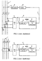
- the scheme of the figure 1 represents a circuit breaker comprising a ground protection device of the prior art.
- an electrical distribution network 1 comprises phase conductors A, B, C and a neutral conductor N.
- phase and neutral currents are carried out with current transformers arranged on each conductor respectively 2A, 2B, 2C and 2N.
- the Current transformers provide phase and neutral signals to a zero-sequence or ground-fault detection circuit 3.
- Generally circuit 3 makes a vector sum to determine the current IG1 representative of a ground fault current.
- the signal IG1 is applied to an input of a processing circuit 4 which comprises a preprocessing module 5 for determining an effective value IGRMS of the signal IG1, and a protection function processing module 6.
- the processing circuit provides a trigger signal 7 if the ground fault signal IG1 exceeds a threshold for a predetermined time.
- the signal 7 is supplied to a relay 8 to control the opening of contacts 10 actuated by a mechanism 9.
- the circuits 3 and 4 and the relay 8 form an electronic trip for a circuit breaker.
- the scheme of the figure 2 shows a different embodiment.
- the value of a ground fault current is measured by a current sensor 11 which surrounds all the phase and neutral conductors.
- the signal supplied by the sensor 11 is applied to a detection circuit 3 which performs, in this case, in particular the shaping and rectification of the signal.
- Circuit 3 supplies a signal IG1 representative of a ground fault current to a processing circuit 4.
- Circuit 4 of the figure 2 comprises a preprocessing module 5 for performing the peak detection of the earth protection signal and provides an IGPIC signal to the protection function processing module 6.
- the duration of said current is short and the pretreatment module in effective value does not correctly detect such a fault.
- a detection directly in effective value reduces the value of the signal and is not representative of the real nuisances that can produce an arc signal. If the detection was in peak value as on the figure 2 the arc currents would then be overestimated and the detection of sinusoidal currents with harmonics would not be accurate.
- the detection of sinusoidal fault current comprising harmonics is precise especially in rms value and the currents comprising pulses of short durations such that the representative arc fault currents are estimated at values greater than those of their effective values.
- the earth protection device comprises a processing module 12 disposed between the detection circuit 3 and a preprocessing module 5.
- the module 12 receives the signal IG1 representative of a ground fault signal and provides a second signal IG2 representative of a ground fault having on decreasing a slope limited to a predetermined value.
- the slope limited to decay is greater than a slope at the decay of a sinusoid.
- the signal IG2 can decrease faster than a sinusoid to preserve the shape of the sinusoidal signals.
- the pretreatment module 5 preferably detects an effective value IGX of the second signal IG2.
- an approximate effective value IGX can also be obtained by filtering or directly integrated into the protection function of the module 6.
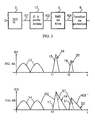
- the Figure 4A shows a corrected IG1 signal representative of a ground fault and the Figure 4B shows an IG2 signal provided by the module 12.
- two first half-waves 13 of the signal IG1 are sinusoidal. If the limited slope is greater than a sinusoidal slope, the signal IG2 has substantially the same shape as the signal IG1. Thus, the first two alternations 14 of the signal IG2 of the Figure 4B look like alternations 13.
- a first signal representative of an arc appears.
- This signal has a high amplitude and a limited duration. In this case, the slope at decay, represented by a portion 16 of the curve, is very high.
- the signal IG2 then has at time t1 a signal 17 corresponding to the signal 15 of the signal IG1.
- the increasing portion of the signal 17 resembles the increasing portion of the signal 15, but a decreasing portion 18 has a decreasing slope limited.
- the signal 17 of IG2 representative of an arc has a longer duration than that of the signal 15 and therefore the effective or average value of IG2 is increased when the signal IG1 is representative of an arc signal.
- a second signal 19 representative of an arc signal appears on IG1.
- This signal also has a slope at very high decay. It will be replaced at output on IG2 by a signal 21 having a slope 22 with limited decay.
- the figure 5 shows an embodiment of a module 12 for a device according to the invention.
- the signal IG1 representative of a homopolar current is applied to the input of a sampling circuit 23 which supplies a sampled signal IG1 (t) to a first input of a maximum detector 24.
- the maximum detector provides a sampled output signal IG2 (t).
- a storage circuit 25 receives and stores the signal IG2 (t) and outputs a sample preceding IG2 (t-1) of the signal IG2 (t).
- a parameterization module 26 provides a value L of the slope of limitation to decay.
- the maximum detector 24 provides the highest signal between the input signal IG1 (t) and the value signal IGL (t) limited to decay. Thus, as soon as the signal IG1 (t) has a slope at the decay that exceeds the limited slope of value L, the detector 24 outputs the signal IGL (t) in place of the signal IG1 (t).
- the figure 6 shows an operating flowchart of a module 12.
- a sampling of the signal IG1 (t) is carried out at a reading step 28.
- the maximum value between IG1 (t) and IGL (t) is assigned to IG2 (t).
- a storage step 31 stores the last value of IG2 (t), thus IG2 (t-1) is equal to IG2 (t).
- the figure 7 shows another embodiment of a module 12.
- the module 12 comprises substantially the same elements as that of the figure 5 .
- a comparator 33 is provided to compare the difference D and the slope limitation value L, and a selector 34 controlled by the comparator provides the output signal IG2 (t).
- the comparator 33 receives the signals IG1 (t) from the sampler 23, the signal IGL (t) of the limitation module 27 controls the selector 34 to apply at the output to the signal IG2 (t) the value IG1 (t) if the difference D is less than the limit L or the value IGL (t) if the difference D is greater than the limit L.
- the figure 8 shows another embodiment of a flowchart that can operate in a module 12.
- This flowchart comprises the 28 reading and 31 storage steps such as that of the figure 6 .
- a comparison step 35 compares the slope limitation value L and the difference D between the stored value IG2 (t-1) and the value of the sample IG1 (t). If the difference is greater than or equal to the value L, a step 36 assigns the output signal IG2 (t) a limiting value such that IG2 (t) is equal to IG2 (t-1) -L. If the difference is less than the value L, a step 37 assigns the output signal IG2 (t) the value of the input signal IG1 (t).
- the slope limitation value L is constant. It can be fixedly predetermined or depend on the last peak value of the ground fault signal IG1.
- the slope limitation value L may be variable as a function of the time which separates it from the last peak of the ground fault signal IG1.
- the slope can be very low near the peak of the signal and become high when the time increases with respect to the last ridge.
- the slope limiting value L may be variable depending on the value of the last peak and the time that separates the samples of IG1 (t) from the last peak of said signal IG1 (t).
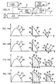
- the figure 9 shows a diagram of a slope value modification device.
- This device comprises a sampling control circuit 38 for controlling the sampler 23 and supplying sampling information S to the parameterization module 26.
- This device also comprises a peak detector 39 receiving the signal IG1 (t) and providing a IGP signal representative of the last peak in the module 26.
- the selection of the type of slope can be performed with a selection module 40 connected to the module 26.
- FIGS 10A and 10D illustrate signals corresponding to different types of decay limiting slopes.
- the slope at decay is different for the signals 42 and 43.
- a slope 46 has a high value
- a slope 47 has a low value.
- the slope may advantageously depend on a last peak 48 of the signal IG1.
- Another advantage of the control of the slope is the control of the time of return to zero of the signal IG2.
- T1 and T2 are different with identical slopes 44 and 45 while on the figure 10B durations T3 and T4 are substantially equivalent with different slopes 46 and 47.
- the slope at the decay is variable as a function of a time between the last peak and a posterior value of the signal IG2.
- the slope has a first value in a portion 49 between instants t5 and t6, a second value in a portion 50 between times t6 and t7, a third value in a portion 51 between times t7 and t8, and a fourth value in a portion 52 between times t8 and t9.
- the instants t5 to t9 can be determined according to the number of samples which separates an instantaneous signal from the instant of the last peak 48.
- the slope at the decay is variable according to a time as in the Figure 10C and also depending on the value of the last peak.
- the portions 49 to 52 may be different at each signal.
- a slope at the decrease according to the figure 10D can simulate a parabolic type curve.
Description
L'invention concerne un dispositif de protection terre comportant une entrée pour recevoir un premier signal représentatif d'un courant de défaut à la terre, des premiers moyens de traitement de signal pour traiter un signal représentatif d'un courant de défaut à la terre, et des moyens de traitement de fonctions de protection connectés aux premiers moyens de traitement de signal.The invention relates to a ground protection device comprising an input for receiving a first signal representative of a ground fault current, first signal processing means for processing a signal representative of a ground fault current, and protection function processing means connected to the first signal processing means.
Les dispositifs de protection terre connus installés dans des déclencheurs ou des disjoncteurs comportent des moyens de détection de courants homopolaires ou de défaut terre. Généralement, ces courants sont détectés en faisant la somme vectorielle de l'ensemble des courants de ligne, c'est à dire des courants de phases et du courant de neutre.Known earth protection devices installed in trip units or circuit breakers comprise means for detecting homopolar currents or ground faults. Generally, these currents are detected by making the vector sum of all line currents, ie phase currents and neutral current.
Cette somme vectorielle peut être réalisée en mesurant séparément des courants dans chaque conducteur de ligne avec des capteurs indépendants puis un dispositif détermine un signal de courant de défaut terre en effectuant la somme des signaux mesurés. Il est également possible de mesurer un courant de défaut terre en utilisant un capteur qui entoure tous les conducteurs. Un signal fourni par un tel capteur est directement représentatif d'un courant de défaut terre.This vector sum can be achieved by separately measuring currents in each line conductor with independent sensors and then a device determines a ground fault current signal by summing the measured signals. It is also possible to measure a ground fault current using a sensor that surrounds all the conductors. A signal provided by such a sensor is directly representative of a ground fault current.
Les signaux représentatifs de courant de défaut terre sont utilisés dans des fonctions de protection pour commander l'ouverture de contacts de disjoncteur ou pour signaler la présence de courant de défaut terre.The earth fault current representative signals are used in protection functions to control the opening of circuit breaker contacts or to signal the presence of earth fault current.
Dans des dispositifs de protection terre connus, les signaux représentatifs des courants de défaut sont traités pour extraire une valeur efficace desdits signaux. Cependant, lorsque les courants de défaut sont causés par des arcs électriques, la durée desdits courants est très faible. La durée des courants d'arc est souvent très inférieure à la période correspondant à la fréquence d'un réseau de distribution électrique. Ces courants de défaut de faible durée n'ont pas une valeur efficace très élevée mais provoquent des nuisances importantes dans des installations électriques. De plus, ces courants d'arc peuvent présenter un danger pour des personnes qui utilisent du matériel connecté au réseau.In known earth protection devices, the signals representative of the fault currents are processed to extract an effective value of said signals. However, when the fault currents are caused by arcing, the duration of said currents is very low. The duration of the arc currents is often much shorter than the period corresponding to the frequency of an electrical distribution network. These short-term fault currents do not have a very high effective value but cause significant nuisances in Electrical installation. In addition, these arc currents can be dangerous for people who use network-connected equipment.
Une détection en valeur efficace ne permet pas de détecter correctement ces courants d'arc. D'autres façon pour détecter des arcs éléctriques sont décrites dans les documents
Il existe des dispositifs qui utilisent des détections en valeur crête. Ces dispositifs peuvent détecter correctement les courant d'arc mais ils ne sont pas suffisamment précis pour détecter des courants présentant des harmoniques.There are devices that use peak value detections. These devices can correctly detect arc currents but they are not accurate enough to detect currents with harmonics.
L'invention a pour but un dispositif de protection terre permettant une détection améliorée des courants de défaut terre comportant des courants d'arcs électriques, ainsi qu'un déclencheur et un disjoncteur comportant un tel dispositif.The object of the invention is to provide a ground protection device for improved detection of earth fault currents comprising electric arc currents, as well as a trigger and a circuit breaker comprising such a device.
Un dispositif selon l'invention comporte des seconds moyens de traitement de signal pour traiter un signal représentatif d'un courant de défaut à la terre connectés entre ladite entrée et les premiers moyens de traitement de signal, lesdits seconds moyens de traitement de signal fournissant aux premiers moyens de traitement de signal un second signal représentatif d'un courant de défaut à la terre ayant à la décroissance une pente inférieure à une valeur de limitation de pente prédéterminéeA device according to the invention comprises second signal processing means for processing a signal representative of a ground fault current connected between said input and the first signal processing means, said second signal processing means providing the first signal processing means a second signal representative of an earth fault current having on decreasing a slope less than a predetermined slope limitation value
Dans un mode de réalisation préférentiel, les seconds moyens de traitement de signal comportent :
- des moyens d'échantillonnage pour échantillonner le premier signal représentatif d'un courant de défaut à la terre,
- des moyens de mémorisation pour mémoriser une dernière valeur du second signal représentatif d'un courant de défaut à la terre,
- des moyens de calcul de décroissance pour calculer une valeur à décroissance limitée connectés aux moyens de mémorisation et à des moyens de fourniture d'une valeur de limitation de pente, la valeur à décroissance limitée étant représentative de la dernière valeur du second signal représentatif d'un courant de défaut à la terre moins la valeur de limitation de pente, et
- des moyens de détermination pour déterminer une nouvelle valeur du second signal représentatif d'un courant de défaut à la terre connectés aux moyens d'échantillonnage et aux moyens de calcul de décroissance.
- sampling means for sampling the first signal representative of a fault current to earth,
- storage means for storing a last value of the second signal representative of a ground fault current,
- decay calculating means for calculating a limited decay value connected to the storage means and means for providing a slope limiting value, the limited decay value being representative of the last value of the second representative signal of a fault current to ground minus the slope limitation value, and
- determining means for determining a new value of the second signal representative of a ground fault current connected to the sampling means and the decay calculating means.
Avantageusement, les moyens de détermination comportent des moyens de détection de maximum pour fournir une nouvelle valeur du second signal représentatif d'un courant de défaut à la terre, ledit second signal étant déterminé en fonction d'une valeur maximale du premier signal échantillonné ou de la valeur à décroissance limitée.Advantageously, the determination means comprise maximum detection means for supplying a new value of the second signal representative of a ground fault current, said second signal being determined as a function of a maximum value of the first sampled signal or of the value with limited decrease.
De préférence, les moyens de détermination comportent :
- des moyens de calcul de différence connectés aux moyens de mémorisation et aux moyens d'échantillonnage pour déterminer la différence entre une valeur du premier signal échantillonné et une dernière valeur du second signal,
- des moyens de comparaison pour comparer ladite différence avec la valeur de limitation de pente, et
- des moyens de sélection ayant des entrées connectées aux moyens d'échantillonnage et aux moyens de calcul de décroissance et étant contrôlés par les moyens de comparaison pour fournir en sortie un signal ayant une valeur à décroissance limitée si la différence entre une valeur du premier signal échantillonné et une dernière valeur du second signal est supérieure à la valeur de limitation de pente.
- difference calculating means connected to the storage means and the sampling means for determining the difference between a value of the first sampled signal and a last value of the second signal,
- comparison means for comparing said difference with the slope limitation value, and
- selection means having inputs connected to the sampling means and the decay calculating means and being controlled by the comparing means for outputting a signal having a limited decay value if the difference between a value of the first sampled signal and a last value of the second signal is greater than the slope limitation value.
Dans un mode de réalisation particulier, la valeur de limitation de pente est constante.In a particular embodiment, the slope limitation value is constant.
Selon une première variante, la valeur de limitation de pente est variable en fonction d'une dernière valeur de crête du premier signal représentatif d'un courant de défaut à la terre.According to a first variant, the slope limitation value is variable as a function of a last peak value of the first signal representative of a ground fault current.
Selon une seconde variante, la valeur de limitation de pente est variable en fonction d'un temps entre une dernière valeur de crête et une valeur instantanée postérieure du premier signal représentatif d'un courant de défaut à la terre.According to a second variant, the slope limitation value is variable as a function of a time between a last peak value and a posterior instantaneous value of the first signal representative of a ground fault current.
Selon une troisième variante, la valeur de limitation de pente est variable en fonction d'une dernière valeur de crête et d'un temps entre une dernière valeur de crête et une valeur instantanée postérieure du premier signal représentatif d'un courant de défaut à la terre.According to a third variant, the slope limitation value is variable as a function of a last peak value and a time between a last peak value and a posterior instantaneous value of the first signal representative of a fault current at the Earth.
De préférence, un procédé de traitement pour le dispositif de protection terre comporte :
- une étape de lecture d'un signal d'entrée représentatif d'un courant de défaut terre,
- une étape de détermination d'une valeur limitée à la décroissance,
- une étape de sélection pour fournir un signal de sortie représentatif d'un courant de défaut terre, ledit signal de sortie étant à décroissance limitée si la différence entre le signal d'entrée et un signal de sortie précédant est supérieur à une valeur de limitation, et
- une étape de mémorisation du signal de sortie.
- a step of reading an input signal representative of a ground fault current,
- a step of determining a value limited to the decrease,
- a selection step for providing an output signal representative of a ground fault current, said output signal being limited decaying if the difference between the input signal and a preceding output signal is greater than a limiting value, and
- a step of storing the output signal.
Avantageusement, le procédé comporte une étape de détection d'une valeur maximale entre le signal d'entrée et la valeur limitée à la décroissanceAdvantageously, the method comprises a step of detecting a maximum value between the input signal and the value limited to the decay.
Un déclencheur électronique selon l'invention comporte un dispositif de protection terre tel que défini ci-dessus.An electronic release according to the invention comprises a ground protection device as defined above.
Un disjoncteur selon l'invention comporte un dispositif de protection terre tel que défini ci-dessus.A circuit breaker according to the invention comprises a ground protection device as defined above.
D'autres avantages et caractéristiques ressortiront plus clairement de la description qui va suivre, de modes particuliers de réalisation de l'invention, donnés à titre d'exemples non limitatifs, et représentés aux dessins annexés sur lesquels :
- la
figure 1 représente un schéma d'un disjoncteur comportant un dispositif de protection terre de l'art antérieur ; - la
figure 2 représente un schéma d'un dispositif de protection terre de l'art antérieur ; - la
figure 3 représente un schéma d'un dispositif de protection terre selon un mode de réalisation de l'invention ; - les
figures 4A et 4B montrent des signaux dans un dispositif de protection terre selon un mode de réalisation de l'invention ; - la
figure 5 représente un schéma d'un module de traitement d'un dispositif de protection terre selon un mode de réalisation de l'invention ; - la
figure 6 représente un organigramme pouvant fonctionner dans un module de traitement d'un dispositif de protection terre selon un mode de réalisation de l'invention ; - la
figure 7 représente un autre schéma d'un module de traitement d'un dispositif de protection terre selon un mode de réalisation de l'invention ; - la
figure 8 représente un autre organigramme pouvant fonctionner dans un module de traitement d'un dispositif de protection terre selon un mode de réalisation de l'invention ; - la
figure 9 représente un schéma d'un dispositif de modification de pente limitée pouvant fonctionner dans un module de traitement d'un dispositif de protection terre selon un mode de réalisation de l'invention ; - les
figures 10A à 10D montrent des signaux de différents types de limitation de pente de modules de traitement de dispositifs de protection terre selon des modes de réalisation de l'invention.
- the
figure 1 represents a diagram of a circuit breaker comprising a ground protection device of the prior art; - the
figure 2 represents a diagram of a ground protection device of the prior art; - the
figure 3 represents a diagram of a ground protection device according to one embodiment of the invention; - the
Figures 4A and 4B show signals in a ground protection device according to one embodiment of the invention; - the
figure 5 represents a diagram of a processing module of a ground protection device according to one embodiment of the invention; - the
figure 6 represents a flow chart operable in a processing module of a ground protection device according to one embodiment of the invention; - the
figure 7 represents another diagram of a processing module of a ground protection device according to one embodiment of the invention; - the
figure 8 represents another flowchart operable in a processing module of a ground protection device according to one embodiment of the invention; - the
figure 9 represents a diagram of a limited slope modification device that can operate in a processing module of a ground protection device according to one embodiment of the invention; - the
Figures 10A to 10D show signals of different types of slope limitation of earth protection device processing modules according to embodiments of the invention.
Le schéma de la
La mesure des courants de phases et de neutre est réalisée avec des transformateurs de courants disposés sur chaque conducteur respectivement 2A, 2B, 2C et 2N. Les transformateurs de courant fournissent des signaux de phase et de neutre à un circuit 3 de détection d'un courant homopolaire ou de protection terre IG1. Généralement le circuit 3 effectue une somme vectorielle pour déterminer le courant IG1 représentatif d'un courant de défaut terre.The measurement of the phase and neutral currents is carried out with current transformers arranged on each conductor respectively 2A, 2B, 2C and 2N. The Current transformers provide phase and neutral signals to a zero-sequence or ground-
Le signal IG1 est appliqué à une entrée d'un circuit de traitement 4 qui comporte un module 5 de prétraitement pour déterminer une valeur efficace IGRMS du signal IG1, et un module 6 de traitement de fonction de protection.The signal IG1 is applied to an input of a
Le circuit de traitement fournit un signal de déclenchement 7 si le signal IG1 de défaut terre dépasse un seuil pendant une durée prédéterminée. Le signal 7 est fourni à un relais 8 pour commander l'ouverture de contacts 10 actionnés par un mécanisme 9. Les circuits 3 et 4 et le relais 8 forment un déclencheur électronique pour un disjoncteur.The processing circuit provides a trigger signal 7 if the ground fault signal IG1 exceeds a threshold for a predetermined time. The signal 7 is supplied to a
Le schéma de la
Le circuit 4 de la
Lorsque le courant de défaut terre est provoqué par un arc électrique, la durée dudit courant est courte et le module de prétraitement en valeur efficace ne permet pas de détecter correctement un tel défaut. Une détection directement en valeur efficace réduit la valeur du signal et n'est pas représentative des véritables nuisances que peut produire un signal d'arc. Si la détection était en valeur crête comme sur la
Dans un dispositif selon l'invention, la détection de courant de défaut sinusoïdaux comportant des harmoniques est précise notamment en valeur efficace et les courants comportant des impulsions de courtes durées tels que les courants représentatifs de défaut d'arc sont estimés à des valeurs supérieures à celles de leurs valeurs efficaces.In a device according to the invention, the detection of sinusoidal fault current comprising harmonics is precise especially in rms value and the currents comprising pulses of short durations such that the representative arc fault currents are estimated at values greater than those of their effective values.
Dans un mode de réalisation de l'invention, représenté sur le schéma bloc de la
De préférence, la pente limitée à la décroissance est supérieure à une pente à la décroissance d'une sinusoïde. Ainsi, le signal IG2 peut décroître plus rapidement qu'une sinusoïde pour préserver la forme des signaux sinusoïdaux.Preferably, the slope limited to decay is greater than a slope at the decay of a sinusoid. Thus, the signal IG2 can decrease faster than a sinusoid to preserve the shape of the sinusoidal signals.
Le module de prétraitement 5 détecte de préférence une valeur efficace IGX du second signal IG2. Dans ledit module 5, une valeur efficace approchée IGX peut aussi être obtenue par filtrage ou directement intégrée dans la fonction de protection du module 6.The
La
Sur les
A un instant tl, un premier signal 15 représentatif d'un arc apparaît. Ce signal a une amplitude élevée et une durée limitée. Dans ce cas, la pente à la décroissance, représentée par une partie 16 de la courbe, est très élevée. Le signal IG2 comporte alors à l'instant t1 un signal 17 correspondant au signal 15 du signal IG1. La partie croissante du signal 17 ressemble à la partie croissante du signal 15, mais une partie décroissante 18 a une pente décroissante limitée. Le signal 17 de IG2 représentatif d'un arc a une durée plus longue que celle du signal 15 et par conséquent la valeur efficace ou moyenne de IG2 est augmentée lorsque le signal IG1 est représentatif d'un signal d'arc.At a time t1, a first signal representative of an arc appears. This signal has a high amplitude and a limited duration. In this case, the slope at decay, represented by a
A un instant t2, un second signal 19 représentatif d'un signal d'arc apparaît sur IG1. Ce signal aussi a une pente 20 à la décroissance très élevée. Il sera remplacé en sortie sur IG2 par un signal 21 ayant une pente 22 à la décroissance limitée.At a time t2, a
La
Un circuit de mémorisation 25 reçoit et mémorise le signal IG2(t) et fournit en sortie un échantillon précédant IG2(t-1) du signal IG2(t).A
Un module de paramétrage 26 fournit une valeur L de la pente de limitation à la décroissance. Un module de limitation 27, recevant en entrée un échantillon précédant IG2(t-1) du circuit de mémorisation 25 et une valeur L de la pente de module de paramétrage 26, détermine un échantillon IGL(t) ayant une valeur limitée à la décroissance et fournit ledit échantillon IGL(t) à une seconde entrée du détecteur de maximum 24. Le signal IGL(t) peut être déterminé selon la formule IGL(t) = IG2(t-1) - L.A
Le détecteur de maximum 24 fournit le signal le plus élevé entre le signal IG1(t) d'entrée et le signal IGL(t) de valeur limitée à la décroissance. Ainsi, dès que le signal IG1(t) a une pente à la décroissance qui dépasse la pente limitée de valeur L, le détecteur 24 applique en sortie le signal IGL(t) à la place du signal IG1(t).
Le signal IG2(t) peut s'exprimer ainsi : IG2(t)=Max [IG1(t); IGL(t)].The
The signal IG2 (t) can be expressed as follows: IG2 (t) = Max [IG1 (t); IGL (t)].
La
La
Le comparateur 33 reçoit les signaux IG1(t) de l'échantillonneur 23, le signal IGL(t) du module de limitation 27 commande le sélecteur 34 pour appliquer en sortie au signal IG2(t) la valeur IG1(t) si la différence D est inférieure à la limite L ou la valeur IGL(t) si la différence D est supérieure à la limite L .The
La
De préférence, la valeur L de limitation de pente est constante. Elle peut être prédéterminée de manière fixe ou dépendre de la dernière valeur de crête du signal IG1 de défaut terre.Preferably, the slope limitation value L is constant. It can be fixedly predetermined or depend on the last peak value of the ground fault signal IG1.
Avantageusement, la valeur L de limitation de pente peut être variable en fonction du temps qui la sépare de la dernière crête du signal IG1 de défaut terre. Par exemple la pente peut être très faible près de la crête du signal et devenir élevée lorsque le temps augmente par rapport à la dernière crête. Dans un autre mode de réalisation, la valeur L de limitation de pente peut être variable en fonction de la valeur de la dernière crête et du temps qui sépare les échantillons de IG1(t) da la dernière crête dudit signal IG1(t).Advantageously, the slope limitation value L may be variable as a function of the time which separates it from the last peak of the ground fault signal IG1. For example, the slope can be very low near the peak of the signal and become high when the time increases with respect to the last ridge. In another embodiment, the slope limiting value L may be variable depending on the value of the last peak and the time that separates the samples of IG1 (t) from the last peak of said signal IG1 (t).
Le
Les
Sur la
Sur la
Par exemple, sur la
Sur la
Sur la
Avantageusement, une pente à la décroissance selon la
Claims (12)
- Earth protection device comprising an input to receive a first signal (IG1) representative of an earth fault current, first signal processing means (5) to process a signal representative of an earth fault current, and processing means (6) of protection functions connected to the first signal processing means (5),
device characterized in that it comprises second signal processing means (12) to process a signal (IG1) representative of an earth fault current connected between said input and the first signal processing means (5), said second signal processing means supplying to the first signal processing means a second signal (IG2) representative of an earth fault current having on decrease a gradient (18, 22, 44-47, 49-52) lower than a preset gradient limiting value (L). - Earth protection device according to claim 1, characterized in that the second signal processing means comprise:- sampling means (23) to sample the first signal representative of an earth fault current,- storing means (25) to store a last value (IG2(t-1)) of the second signal representative of an earth fault current,- decrease calculating means (27) to calculate a value (IGL(t)) with limited decrease connected to the storing means and to means (26) for supplying a gradient limiting value (L), the value with limited decrease being representative of the last value (IG2(t-1)) of the second signal representative of an earth fault current less the gradient limiting value (L), and- determining means (24) for determining a new value of the second signal (IG2(t)) representative of an earth fault current connected to the sampling means (23) and to the decrease calculating means (27, 32, 33, 34).
- Earth protection device according to claim 2, characterized in that the determining means comprise means (24) for detecting a maximum to supply a new value (IG2(t)) of the second signal representative of an earth fault current, said second signal being determined according to a maximum value of the first sampled signal (IG1(t)) or of the limited decrease value (IGL(t)).
- Earth protection device according to one of claims 2 or 3, characterized in that the determining means comprise:- means (32) for calculating a difference (D) connected to the storing means (25) and to the sampling means (23) to determine the difference between a value (IG1(t)) of the first sampled signal and a last value (IG2(t-1)) of the second signal,- comparison means (33) to compare said difference (D) with the gradient limiting value (L), and- selection means (34) having inputs connected to the sampling means (23) and to the decrease calculating means (27) and being controlled by the comparison means (33) to supply on output a signal having a limited decrease value (IG2(t)) if the difference between a value (IG1(t)) of the first sampled signal and a last value (IG2(t-1)) of the second signal is greater than the gradient limiting value (L).
- Earth protection device according to any one of claims 1 to 4, characterized in that the gradient limiting value (L) is constant.
- Earth protection device according to any one of claims 1 to 5, characterized in that the gradient limiting value (L) is variable according to a last peak value (IGP) of the first signal (IG1) representative of an earth fault current.
- Earth protection device according to any one of claims 1 to 6, characterized in that the gradient limiting value (L) is variable according to a time (t6, t7, t8, t9) between a last peak value (48) and a subsequent instantaneous value of the first signal representative of an earth fault current.
- Earth protection device according to any one of claims 2 to 7, characterized in that the gradient limiting value (L) is variable according to a last peak value (IGP) and to a time (t6, t7, t8, t9) between a last peak value and a subsequent instantaneous value of the first signal representative of an earth fault current.
- Method for an earth protection device according to any one of claims 2 to 8, characterized in that it comprises:- a read step (28) of an input signal (IG1(t)) representative of an earth fault current,- a step (29) for determining a limited decrease value (IGL(t)),- a selection step (30) to supply an output signal (IG2(t)) representative of an earth fault current, said output signal being with limited decrease if the difference between the input signal (IG1(t)) and a previous output signal (IG2(t-1)) is greater than a limiting value (L), and- an output signal storing step (31).
- Method according to claim 9, characterized in that it comprises a step (30) for detecting a maximum value (IG2(t)) between the input signal (IG1(t)) and the limited decrease value (IGL(t)).
- Electronic trip device comprising an earth protection device according to any one of claims 2 to 8.
- Circuit breaker comprising an earth protection device according to any one of claims 2 to 8.
Applications Claiming Priority (2)
| Application Number | Priority Date | Filing Date | Title |
|---|---|---|---|
| FR9911489A FR2798527B1 (en) | 1999-09-10 | 1999-09-10 | EARTH PROTECTION DEVICE SENSITIVE TO ARC CURRENTS, TRIGGER AND CIRCUIT BREAKER COMPRISING SUCH A DEVICE |
| FR9911489 | 1999-09-10 |
Publications (2)
| Publication Number | Publication Date |
|---|---|
| EP1083644A1 EP1083644A1 (en) | 2001-03-14 |
| EP1083644B1 true EP1083644B1 (en) | 2010-08-04 |
Family
ID=9549830
Family Applications (1)
| Application Number | Title | Priority Date | Filing Date |
|---|---|---|---|
| EP00410096A Expired - Lifetime EP1083644B1 (en) | 1999-09-10 | 2000-08-11 | Earth fault protection device sensitive to arc currents, trip device and circuit breaker comprising such a device |
Country Status (7)
| Country | Link |
|---|---|
| US (1) | US6437952B1 (en) |
| EP (1) | EP1083644B1 (en) |
| CA (1) | CA2316050C (en) |
| DE (1) | DE60044765D1 (en) |
| FR (1) | FR2798527B1 (en) |
| MX (1) | MXPA00008565A (en) |
| ZA (1) | ZA200004332B (en) |
Families Citing this family (1)
| Publication number | Priority date | Publication date | Assignee | Title |
|---|---|---|---|---|
| FR2798526B1 (en) * | 1999-09-15 | 2001-11-09 | Schneider Electric Ind Sa | ELECTRONIC TRIGGER WITH OFFSET CORRECTION MEANS |
Family Cites Families (3)
| Publication number | Priority date | Publication date | Assignee | Title |
|---|---|---|---|---|
| FR2719124B1 (en) * | 1994-04-21 | 1996-06-07 | Merlin Gerin | Method and device for correcting a current signal. |
| US5726577A (en) * | 1996-04-17 | 1998-03-10 | Eaton Corporation | Apparatus for detecting and responding to series arcs in AC electrical systems |
| US5818237A (en) * | 1996-06-10 | 1998-10-06 | Eaton Corporation | Apparatus for envelope detection of low current arcs |
-
1999
- 1999-09-10 FR FR9911489A patent/FR2798527B1/en not_active Expired - Lifetime
-
2000
- 2000-07-14 US US09/617,124 patent/US6437952B1/en not_active Expired - Lifetime
- 2000-08-11 EP EP00410096A patent/EP1083644B1/en not_active Expired - Lifetime
- 2000-08-11 DE DE60044765T patent/DE60044765D1/en not_active Expired - Lifetime
- 2000-08-16 CA CA2316050A patent/CA2316050C/en not_active Expired - Fee Related
- 2000-08-23 ZA ZA200004332A patent/ZA200004332B/en unknown
- 2000-09-01 MX MXPA00008565A patent/MXPA00008565A/en active IP Right Grant
Also Published As
| Publication number | Publication date |
|---|---|
| ZA200004332B (en) | 2001-03-12 |
| CA2316050C (en) | 2010-10-12 |
| FR2798527B1 (en) | 2001-11-09 |
| CA2316050A1 (en) | 2001-03-10 |
| DE60044765D1 (en) | 2010-09-16 |
| US6437952B1 (en) | 2002-08-20 |
| EP1083644A1 (en) | 2001-03-14 |
| FR2798527A1 (en) | 2001-03-16 |
| MXPA00008565A (en) | 2005-09-08 |
Similar Documents
| Publication | Publication Date | Title |
|---|---|---|
| EP0407310B1 (en) | Static trip unit with a desensibilisation system for earth protection | |
| EP0396477B1 (en) | Static trip device for a circuit breaker, protecting a three-phase network, allowing the detection of the fault-type | |
| EP2383856B1 (en) | Identification and directional detection of a defect in a three-phase network | |
| EP1890165B1 (en) | Method of directional detection of a fault in the ground connection and device for implementing the same | |
| EP2687860B1 (en) | Directional detection of a sensitive medium-voltage earth fault by linear correlation | |
| EP1475874A1 (en) | Device and method for detecting an earth fault and relay with such a device | |
| EP0568471B1 (en) | Device for monitoring a homopolar fault in a mains supply | |
| EP3384592B1 (en) | Method and device for detecting an electric arc in a photovoltaic installation | |
| EP0053069A1 (en) | Process for determining the direction of a fault origin, in an electric distribution system | |
| EP1318586B1 (en) | Method and device for electrical short circuit detection, and circuit breaker comprising such a device | |
| EP0592337B1 (en) | Electronic trip device comprising earth protection | |
| EP1083644B1 (en) | Earth fault protection device sensitive to arc currents, trip device and circuit breaker comprising such a device | |
| EP0605335B1 (en) | Electronic trip device comprising a testing device | |
| EP0678960B1 (en) | Method and apparatus for correcting a current signal | |
| EP0591011B1 (en) | Device for detecting faults on an electric energy distributing underground network | |
| EP1357386B1 (en) | Device and method for electrical charge detection and electrical apparatus equipped with such a device | |
| EP3033760A1 (en) | Method, device and computer program for controlling a mechatronic circuit breaker | |
| WO2009144083A1 (en) | Method and system for detecting residual secondary current in current transformer in high tension electrical network, and for detecting arc formation in circuit breaker | |
| EP0540379A1 (en) | Centralised differential circuit breaker | |
| FR2650711A1 (en) | Control relay for shunt circuit breaker with separate poles | |
| FR2786916A1 (en) | DEVICE FOR CONTROLLING AN ELECTRO-MAGNET WITH LOCAL CONTROL INPUT |
Legal Events
| Date | Code | Title | Description |
|---|---|---|---|
| PUAI | Public reference made under article 153(3) epc to a published international application that has entered the european phase |
Free format text: ORIGINAL CODE: 0009012 |
|
| AK | Designated contracting states |
Kind code of ref document: A1 Designated state(s): DE GB IT |
|
| AX | Request for extension of the european patent |
Free format text: AL;LT;LV;MK;RO;SI |
|
| 17P | Request for examination filed |
Effective date: 20010523 |
|
| AKX | Designation fees paid |
Free format text: DE GB IT |
|
| RAP1 | Party data changed (applicant data changed or rights of an application transferred) |
Owner name: SCHNEIDER ELECTRIC INDUSTRIES SAS |
|
| 17Q | First examination report despatched |
Effective date: 20081107 |
|
| RAP1 | Party data changed (applicant data changed or rights of an application transferred) |
Owner name: SCHNEIDER ELECTRIC INDUSTRIES SAS |
|
| GRAP | Despatch of communication of intention to grant a patent |
Free format text: ORIGINAL CODE: EPIDOSNIGR1 |
|
| RIN1 | Information on inventor provided before grant (corrected) |
Inventor name: SUPTITZ, ERIC Inventor name: BLANCHARD, PIERRE |
|
| GRAS | Grant fee paid |
Free format text: ORIGINAL CODE: EPIDOSNIGR3 |
|
| GRAA | (expected) grant |
Free format text: ORIGINAL CODE: 0009210 |
|
| AK | Designated contracting states |
Kind code of ref document: B1 Designated state(s): DE GB IT |
|
| REG | Reference to a national code |
Ref country code: GB Ref legal event code: FG4D Free format text: NOT ENGLISH |
|
| REF | Corresponds to: |
Ref document number: 60044765 Country of ref document: DE Date of ref document: 20100916 Kind code of ref document: P |
|
| PLBE | No opposition filed within time limit |
Free format text: ORIGINAL CODE: 0009261 |
|
| STAA | Information on the status of an ep patent application or granted ep patent |
Free format text: STATUS: NO OPPOSITION FILED WITHIN TIME LIMIT |
|
| 26N | No opposition filed |
Effective date: 20110506 |
|
| REG | Reference to a national code |
Ref country code: DE Ref legal event code: R097 Ref document number: 60044765 Country of ref document: DE Effective date: 20110506 |
|
| REG | Reference to a national code |
Ref country code: DE Ref legal event code: R084 Ref document number: 60044765 Country of ref document: DE |
|
| PGFP | Annual fee paid to national office [announced via postgrant information from national office to epo] |
Ref country code: DE Payment date: 20180730 Year of fee payment: 19 Ref country code: IT Payment date: 20180823 Year of fee payment: 19 |
|
| PGFP | Annual fee paid to national office [announced via postgrant information from national office to epo] |
Ref country code: GB Payment date: 20190814 Year of fee payment: 20 |
|
| REG | Reference to a national code |
Ref country code: DE Ref legal event code: R119 Ref document number: 60044765 Country of ref document: DE |
|
| PG25 | Lapsed in a contracting state [announced via postgrant information from national office to epo] |
Ref country code: DE Free format text: LAPSE BECAUSE OF NON-PAYMENT OF DUE FEES Effective date: 20200303 |
|
| PG25 | Lapsed in a contracting state [announced via postgrant information from national office to epo] |
Ref country code: IT Free format text: LAPSE BECAUSE OF NON-PAYMENT OF DUE FEES Effective date: 20190811 |
|
| REG | Reference to a national code |
Ref country code: GB Ref legal event code: PE20 Expiry date: 20200810 |
|
| PG25 | Lapsed in a contracting state [announced via postgrant information from national office to epo] |
Ref country code: GB Free format text: LAPSE BECAUSE OF EXPIRATION OF PROTECTION Effective date: 20200810 |