EP0053069A1 - Process for determining the direction of a fault origin, in an electric distribution system - Google Patents
Process for determining the direction of a fault origin, in an electric distribution system Download PDFInfo
- Publication number
- EP0053069A1 EP0053069A1 EP81401820A EP81401820A EP0053069A1 EP 0053069 A1 EP0053069 A1 EP 0053069A1 EP 81401820 A EP81401820 A EP 81401820A EP 81401820 A EP81401820 A EP 81401820A EP 0053069 A1 EP0053069 A1 EP 0053069A1
- Authority
- EP
- European Patent Office
- Prior art keywords
- transient power
- point
- wave
- power wave
- protected section
- Prior art date
- Legal status (The legal status is an assumption and is not a legal conclusion. Google has not performed a legal analysis and makes no representation as to the accuracy of the status listed.)
- Granted
Links
Images
Classifications
-
- G—PHYSICS
- G01—MEASURING; TESTING
- G01R—MEASURING ELECTRIC VARIABLES; MEASURING MAGNETIC VARIABLES
- G01R31/00—Arrangements for testing electric properties; Arrangements for locating electric faults; Arrangements for electrical testing characterised by what is being tested not provided for elsewhere
- G01R31/08—Locating faults in cables, transmission lines, or networks
- G01R31/081—Locating faults in cables, transmission lines, or networks according to type of conductors
- G01R31/085—Locating faults in cables, transmission lines, or networks according to type of conductors in power transmission or distribution lines, e.g. overhead
-
- H—ELECTRICITY
- H02—GENERATION; CONVERSION OR DISTRIBUTION OF ELECTRIC POWER
- H02H—EMERGENCY PROTECTIVE CIRCUIT ARRANGEMENTS
- H02H7/00—Emergency protective circuit arrangements specially adapted for specific types of electric machines or apparatus or for sectionalised protection of cable or line systems, and effecting automatic switching in the event of an undesired change from normal working conditions
- H02H7/26—Sectionalised protection of cable or line systems, e.g. for disconnecting a section on which a short-circuit, earth fault, or arc discharge has occured
- H02H7/265—Sectionalised protection of cable or line systems, e.g. for disconnecting a section on which a short-circuit, earth fault, or arc discharge has occured making use of travelling wave theory
Definitions
- FIG. 5 represents a device suitable, in the general case, for implementing the method of the invention.
Abstract
Procédé pour déterminer, en un point de mesure d'un réseau de transport d'énergie électrique, situé à une extrémité d'une section protégée d'un élément de ce réseau, la direction qui, à partir de ce point, indique l'origine d'une perturbation affectant cet élément, ce procédé consistant à mettre en évidence la différence (formée en 14) entre un signal représentatif d'une onde de puissance transitoire aller (formé en 13 A) et un signal représentatif d'une onde de puissance transitoire retour (formé en 13 B) et à déduire ladite direction de la nature du signe algébrique (mis en évidence en 17) de l'intégrale (formée en 16) de cette différence. Pour augmenter la sécurité du résultat, le signal représentatif de l'onde aller pris en compte est retardé (en 12) par rapport au signal représentatif de l'onde retour.Method for determining, at a measurement point of an electrical energy transport network, situated at one end of a protected section of an element of this network, the direction which, from this point, indicates the origin of a disturbance affecting this element, this process consisting in highlighting the difference (formed at 14) between a signal representative of a transient forward power wave (formed at 13 A) and a signal representative of a wave of transient return power (formed in 13 B) and to deduce said direction from the nature of the algebraic sign (highlighted in 17) from the integral (formed in 16) from this difference. To increase the safety of the result, the signal representative of the outgoing wave taken into account is delayed (at 12) with respect to the signal representative of the return wave.
Description
La présente invention concerne un procédé pour déterminer, en un point de mesure d'un réseau de transport d'énergie électrique, situé à une extrémité d'une section protégée d'un élément de ce réseau, tel qu'une ligne de transport d'électricité, la direction qui, à partir de ce point, indique l'origine d'une perturbation affectant cet élément, ce procédé comprenant les étapes consistant à mettre en évidence, à partir de signaux de mesure de tension et de courant audit point de mesure, une grandeur ayant le signe algébrique de l'intégrale de la différence entre une onde de puissance transitoire aller passant par le point de mesure et progressant de l'extérieur de la section protégée vers cette section, et une onde de puissance transitoire retour passant par le point de mesure et progressant de la section protégée vers l'extérieur de cette section, ladite intégrale représentant l'énergie transitoire totale passant par le point de mesure, et à déduire ladite direction de la nature du signe algébrique de ladite grandeur déterminée.The present invention relates to a method for determining, at a measurement point of an electrical energy transport network, located at one end of a protected section of an element of this network, such as a transmission line of electricity, the direction which, from this point, indicates the origin of a disturbance affecting this element, this method comprising the steps consisting in highlighting, from voltage and current measurement signals at said point of measurement, a quantity having the algebraic sign of the integral of the difference between a wave of transient power going passing through the point of measurement and progressing from the outside of the protected section towards this section, and a wave of transient power passing passing by the measuring point and progressing from the protected section towards the outside of this section, said integral representing the total transient energy passing through the measuring point, and deducing said direction from the nature of the sign algebraic of said determined quantity.
On sait que les réseaux de transport d'énergie électrique sont le siège de perturbations électriques diverses, telles que branchements ou débranchements de générateurs ou de charges, les plus graves de ces perturbations, dénommées défauts, consistant par exemple en des court- circuits d'un ou plusieurs des câbles d'une ligne à la terre, ou, dans le cas d'un réseau à courant polyphasé, entre les câbles d'une même ligne qui sont affectés à des phases différentes.It is known that the electrical energy transport networks are the seat of various electrical disturbances, such as connections or disconnections of generators or loads, the most serious of these disturbances, called faults, consisting for example of short circuits of one or more of the cables of a line to earth, or, in the case of a polyphase current network, between the cables of the same line which are assigned to different phases.
Pour prévenir les effets destructeurs des défauts, les réseaux de transport d'énergie électrique sont dotés de détecteurs et de dispositifs complexes de contrôle et de commande propres à assurer, dans les délais les plus brefs après l'apparition du défaut, la protection de l'élément de réseau en défaut, par exemple de la ligne ou du transformateur,par la mise hors circuit de cet élément.To prevent the destructive effects of faults, the electrical energy transport networks are fitted with detectors and complex monitoring and control devices capable of ensuring, as soon as possible after the appearance of the fault, the protection of the 'element of a faulty network, for example of the line or the transformer, by switching off this element.
Compte tenu de ce que chaque détecteur effectue des mesures instantanées de courant et de tension en un point donné de l'élément de réseau, il est nécessaire, en ce point de mesure, non seulement de pouvoir mettre en évidence l'existence d'un défaut sur l'élément de réseau mais également de pouvoir déterminer de quel côté de ce point se trouve le défaut.Given that each detector performs instantaneous measurements of current and voltage at a given point of the network element, it is necessary, at this measurement point, not only to be able to demonstrate the existence of a fault on the network element but also to be able to determine on which side of this point the fault is located.
On sait depuis longtemps que l'apparition d'un défaut sur un élément de réseau engendre une énergie transitoire par phase dont la polarité indique le sens de déplacement, donc la direction de l'origine du défaut par rapport au point de mesure.It has been known for a long time that the appearance of a fault on a network element generates a transient energy per phase whose polarity indicates the direction of movement, therefore the direction of the origin of the fault relative to the measurement point.
Tradionnellement, on utilise deux détecteurs, connus sous le nom de relais directionnels, chaque relais étant disposé à l'extrémité d'une section à protéger d'un élément d'un réseau de transport d'énergie électrique. Cette section est généralement choisie de façon à ne comporter aucun équipement susceptible d'engendrer des perturbations en service normal, et chaque relais a pour fonction de détecter si une perturbation provient de la section protégée ou non. Pour ce faire chaque relais surveille, pendant un certain temps au moins après le début de toute perturbation détectée, le signe de l'énergie transitoire totale passant au point de mesure, par exemple mis en évidence par la similitude ou la disparité des signes de la tension et de l'intensité dé I' onde transitoire. pour chaque perturbation, les directions détectées par les relais sont comparées, par exemple par communication radio. Si les deux relais indiquent que la perturbation provient de la section protégée, des mesures sont immédiatement prises pour protéger l'élément de réseau concerné; dans le cas contraire, la perturbation est considérée comme étant externe à la section protégée.Traditionally, two detectors are used, known as directional relays, each relay being arranged at the end of a section to be protected from an element of an electrical energy transport network. This section is generally chosen so as not to include any equipment capable of causing disturbances in normal service, and each relay has the function of detecting whether a disturbance comes from the protected section or not. To do this, each relay monitors, for at least a certain time after the start of any detected disturbance, the sign of the total transient energy passing to the measurement point, for example highlighted by the similarity or the disparity of the signs of the voltage and intensity of the transient wave. for each disturbance, the directions detected by the relays are compared, for example by radio communication. If the two relays indicate that the disturbance comes from the protected section, measures are immediately taken to protect the network element concerned; otherwise, the disturbance is considered to be external to the protected section.
Une difficulté survient dans le cas où l'impédance en amont du relais est faible, par exemple, pour une ligne de transport d'électricité, dans le cas où la seule impédance significative à l'extérieur de la section protégée est celle d'un puissant générateur d'énergie électrique connecté à la ligne à proximité du relais.A difficulty arises in the case where the impedance upstream of the relay is low, for example, for an electricity transmission line, in the case where the only significant impedance outside the protected section is that of a powerful electrical energy generator connected to the line near the relay.
En effet si l'on considère, en théorie, l'énergie transitoire totale passant au point de mesure comme l'intégrale en fonction du temps de la différence entre une onde de puissance transitoire aller, progressant de l'extérieur de la section protégée, ou amont, vers cette section, et une onde de puissance transitoire retour, progressant de la section protégée vers l'extérieur, il apparait que la détection de la direction du défaut est d'autant plus délicate que les ondes aller et retour sont semblables en amplitude et voisines dans le temps, la raison en étant que le signe d'une grandeur physique positive ou négative et très proche de zéro est empreint d'une grande incertitude. Or, dans le cas d'un défaut affectant la section protégée et de l'existence d'une faible impédance en amont du relais directionnel, l'onde aller est constituée par la réflexion de l'onde retour en amont du relais, et ces deux ondes ont des amplitudes très voisines, en raison de l'absence quasi totale d'atténuation, et sont très proches dans le temps.Indeed if we consider, in theory, the total transient energy passing to the measurement point as the integral as a function of time of the difference between a wave of transient power going, progressing outside the protected section, or upstream, towards this section, and a return transient power wave, progressing from the protected section outwards, it appears that the detection of the direction of the fault is all the more delicate as the outgoing and return waves are similar in amplitude and neighbors in time, the reason being that the sign of a positive or negative physical quantity and very close to zero is marked by great uncertainty. However, in the case of a fault affecting the protected section and the existence of a low impedance upstream of the directional relay, the outgoing wave is formed by the reflection of the return wave upstream of the relay, and these two waves have very similar amplitudes, due to the almost total absence of attenuation, and are very close in time.
Il en résulte, dans la détermination de la direction de l'origine du défaut par rapport au point de mesure, un risque d'erreur que la présente invention a précisément pour but de supprimer.As a result, in determining the direction of the origin of the fault with respect to the measurement point, a risk of error which the present invention is precisely intended to eliminate.
Le procédé de l'invention, qui comprend de façon connue les opérations consistant à mettre en évidence une grandeur dont le signe algébrique est celui de l'énergie transitoire totale passant au point de mesure et à déduire, de la nature du signe algébrique de cette grandeur, la direction de l'origine de la perturbation, est essentiellement caractérisé en ce que ladite grandeur a un module sensiblement égal, à une constante multiplicative près, à l'intégrale de la différence instantanée entre l'onde de puissance transitoire aller, retardée d'un temps compris entre zéro et le double du temps de propagation d'une onde de puissance transitoire sur la section protégée, et l'onde de puissance transitoire retour.The method of the invention, which comprises in a known manner the operations consisting in highlighting a quantity whose algebraic sign is that of the total transient energy passing to the measurement point and in deducing, from the nature of the algebraic sign of this quantity, the direction of the origin of the disturbance, is essentially characterized in that said quantity has a modulus substantially equal, to within a multiplicative constant, to the integral of the instantaneous difference between the forward transient power wave, delayed a time between zero and double the propagation time of a transient power wave on the protected section, and the transient power wave return.
Il est bien entendu, dès à présent et pour la suite de la description, que les expressions telles que "onde de puissance", "différence d'ondes de puissance" et "intégrale de la différence des ondes de puissance" peuvent évidemment désigner les grandeurs physiques ainsi dénommées mais également, par souci de concision, les signaux représentatifs de ces grandeurs physiques.It is understood, from now on and for the remainder of the description, that expressions such as "power wave", "difference in power waves" and "integral of the difference in power waves" can obviously designate the physical quantities thus called but also, for the sake of brevity, the signals representative of these physical quantities.
Dans le cas où l'élément de réseau est une ligne présentant une capacité répartie négligeable, l'onde de puissance transitoire aller peut être obtenue à tout instant, en simulant, à partir de l'onde de puissance transitoire aller passant par le point de mesure à cet instant et des caractéristiques de la ligne, la fraction de l'onde de puissance transitoire aller qui, ayant traversé le point de mesure, passera ou au moins devrait passer,à un instant postérieur, en un point de la section protégée, distant du point de mesure, par exemple au milieu de la section protégée.In the case where the network element is a line having a negligible distributed capacity, the outgoing transient power wave can be obtained at any time, by simulating, from the outgoing transient power wave passing through the point of measurement at this instant and of the characteristics of the line, the fraction of the transient power wave going which, having crossed the point of measurement, will pass or at least should pass, at a later instant, in a point of the protected section, distant from the measurement point, for example in the middle of the protected section.
D'autres caractéristiques et avantages de l'invention ressortiront clairement de la description qui en est faite ci-après, à titre indicatif et nullement limitatif, en référence au dessin annexé sur lequel :
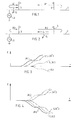
- La figure 1 est un schéma représentant un câble d'une ligne de transport d'énergie électrique, avec une section protégée par deux relais directionnels, un élément de faible impédance extérieur à la section protégée et un défaut également extérieur à la section protégée.
- La figure 2 est un schéma représentant un câble d'une ligne de transport d'énergie électrique avec une section protégée par deux relais directionnels, un élément de faible impédance extérieur à la section protégée, et un défaut dans cette section.
- Les figures 3 et 4 sont des diagrammes respectivement correspondants aux figures 1 et 2 et représentant chacun, en ordonnée positive, dans un référentiel d'énergie E en fonction du temps t, l'intégrale de l'onde de puissance transitoire progressant de l'extérieur de la section protégée vers cette section (onde aller), et, en ordonnée négative, l'intégrale de l'onde de puissance transitoire progressant en sens inverse (onde retour).
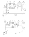
- La figure 5 est un schéma d'un dispositif pour la mise en oeuvre du procédé de l'invention.
- La figure 6 est un schéma d'un autre dispositif pour la mise en oeuvre du procédé de l'invention, applicable au cas d'une ligne présentant une capacité répartie négligeable.
- FIG. 1 is a diagram representing a cable of an electric power transmission line, with a section protected by two directional relays, an element of low impedance outside the protected section and a fault also outside the protected section.
- FIG. 2 is a diagram representing a cable of an electric power transmission line with a section protected by two directional relays, an element of low impedance outside the protected section, and a fault in this section.
- FIGS. 3 and 4 are diagrams respectively corresponding to FIGS. 1 and 2 and each representing, on the positive ordinate, in an energy reference frame E as a function of time t, the integral of the transient power wave progressing from outside the protected section towards this section (outgoing wave), and, on the negative ordinate, the integral of the transient power wave advancing in the opposite direction (return wave).
- FIG. 5 is a diagram of a device for implementing the method of the invention.
- FIG. 6 is a diagram of another device for implementing the method of the invention, applicable to the case of a line having a negligible distributed capacity.
Sur les figures 1 et 2 sont représentés un câble 1 d'une ligne de transport d'énergie électrique, un générateur 2 d'énergie électrique connecté à la ligne, et deux relais directionnels 3 et 4 protégeant la section de ligne qui se trouve comprise entre eux, le générateur 2 présentant une impédance faible et constituant l'élément impédant essentiel en amont du relais 3.In FIGS. 1 and 2 are shown a
Le câble 1 est affecté au transport d'une phase dans le cas d'un courant polyphasé, et le générateur 2 est à l'extérieur de la section protégée, à proximité du relais directionnel 3.The
Si un défaut 5 survient sur la ligne entre le générateur 2 et le relais 3, il apparait une onde de puissance transitoire Al, dite "aller" pour la raison qu'elle se dirige vers la section protégée (flèches en traits pleins sur la figure 1), dont l'intégrale en fonction du temps adopte par exemple la forme JA1 représentée sur la figure 3, également en trait plein. Cette onde "aller" est réfléchie au-delà de l'autre relais directionnel, 4, et forme une onde retour Rl à laquelle correspond l'intégrale JRl (en pointillés sur les figures 1 et 3).If a
Au niveau du relais 3, l'onde retour présente par rapport à l'onde aller d'une part une amplitude sensiblement atténuée en raison de la perte d'énergie qui s'est produite à la réflexion et au cours de la propagation de l'onde sur le double au moins de la longueur de la section protégée, et d'autre part un décalage sensible dans le temps, correspondant au temps de propagation sur le double au moins de la longueur de la section protégée.At
Cette atténuation et ce décalage temporel, qui se retrouvent sur les intégrales JA1 et JR1 de ces ondes de puissance, sont mis clairement en évidence sur la figure 3, sur laquelle les intégrales des ondes de puissance sont représentées avec des formes arbitraires et sur laquelle les énergies JA1 et JR1 sont représentées en ordonnées respectivement positive et négative.This attenuation and this time shift, which are found on the integrals JA1 and JR1 of these power waves, are clearly highlighted in FIG. 3, on which the integrals of the power waves are represented with arbitrary forms and on which the energies JA1 and JR1 are represented on the positive and negative ordinates respectively.
Si SJR1 désigne la courbe symétrique de JR1 par rapport à l'axe des abscisses t , l'énergie transitoire totale qui s'est déjà manifestée, pour une phase, au temps t , est représentée par la différence, de signe positif, entre l'ordonnée de JA1 et celle de SJR1 pour ce même temps t. La figure 3 montre clairement que cette différence a un module relativement important, de sorte que le signe de cette différence peut être identifié de façon aisée.If SJR1 designates the symmetrical curve of JR1 with respect to the abscissa axis t, the total transient energy which has already manifested itself, for a phase, at time t, is represented by the difference, of positive sign, between l 'ordinate of JA1 and that of SJR1 for this same time t. Figure 3 clearly shows that this difference has a relatively large modulus, so that the sign of this difference can be identified easily.
Par contre si l'on considère maintenant les figures 2 et 4, illustrant le cas où un défaut 5 survient sur la section protégée, on remarque que la situation est sensiblement différente.By cons if we now consider Figures 2 and 4, illustrating the case where a
Le relais directionnel 3 reçoit d'abord l'onde retour R2, à laquelle correspond l'intégrale JR2, (en traits pleins sur les figures 2 et 4), et cette onde se réfléchit sur l'élément de faible impédance 2 pour constituer l'onde aller A2, à laquelle correspond l'intégrale JA2 (en pointillés sur les figures 2 et 4). Mais, compte tenu de ce que la réflexion est alors quasi totale et de ce que le trajet du relais 3 au générateur 2 est court, l'onde aller passe par le relais 3 très peu de temps après l'onde retour et avec sensiblement la même amplitude.The
Cet effet, qui se retrouve sur les intégrales JA2 et JR2 des ondes de puissance aller et retour, est mis en évidence sur la figure 4.This effect, which is found on the integrals JA2 and JR2 of the waves of power back and forth, is highlighted in Figure 4.
Les courbes représentées sur cette figure ont des formes arbitraires et les énergies JA2 et JR2 sont représentées en ordonnées respectivement positive et négative.The curves shown in this figure have arbitrary shapes and the energies JA2 and JR2 are represented on the positive and negative ordinates respectively.
Si SJA2 désigne la courbe symétrique de JA2 par rapport à l'axe des abscisses t , l'énergie transitoire qui s'est déjà manifestée, pour une phase, au temps t , est représentée par la différence, de signe négatif, entre l'ordonnée de JR2 et celle de SJA2 pour ce même temps t . La figure 4 montre clairement que cette différence a un module faible, de sorte que la détermination du signe algébrique de cette différence est entachée d'un risque d'erreur important.If SJA2 designates the symmetrical curve of JA2 with respect to the abscissa axis t, the transient energy which has already manifested itself, for a phase, at time t, is represented by the difference, of negative sign, between the ordinate of JR2 and that of SJA2 for this same time t. FIG. 4 clearly shows that this difference has a low modulus, so that the determination of the algebraic sign of this difference is vitiated by a significant risk of error.
Le procédé de l'invention consiste essentiellement à retarder le signal représentatif de l'onde de puissance aller A2 (en pointillés sur la figure 2) d'un intervalle de temps compris entre zéro et le double du temps de propagation d'une onde de puissance transitoire sur la longueur de la section protégée; de préférence, cet intervalle de temps est choisi égal à ce temps de propagation lui-même.The method of the invention essentially consists in delaying the signal representative of the outgoing power wave A2 (in dotted lines in FIG. 2) by a time interval between zero and twice the propagation time of a wave of transient power over the length of the protected section; preferably, this time interval is chosen to be equal to this propagation time itself.
A l'onde de puissance, dont ce signal retardé est représentatif, correspond une intégrale temporelle ou énergie JA'2, retardée par rapport à JA2. Si SJA'2 désigne la courbe symétrique de JA'2 par rapport à l'axe des temps, la grandeur dont le signe algébrique est pris en considération pour la détermination de la direction de l'origine du défaut est,suivant l'invention, la différence entre les ordonnées correspondantes des courbes JR2 et SJA'2 ou toute grandeur proportionnelle à cette différence. Comme on le constate en observant la figure 4 cette différence a un module supérieur à celui de la différence entre les ordonnées de JR2 et SJA2, de sorte que son signe peut être identifié avec une plus grande sécùrité.The power wave, of which this delayed signal is representative, corresponds to a time integral or energy JA'2, delayed with respect to JA2. If SJA'2 designates the symmetrical curve of JA'2 with respect to the time axis, the quantity whose algebraic sign is taken into account for the determination of the direction of the origin of the fault is, according to the invention, the difference between the corresponding ordinates of the curves JR2 and SJA'2 or any quantity proportional to this difference. As can be seen by observing FIG. 4, this difference has a modulus greater than that of the difference between the ordinates of JR2 and SJA2, so that its sign can be identified with greater security.
Il convient évidemment de faire remarquer que le retard virtuellement introduit dans l'onde aller est aussi responsable, (figure 3) du déplacement de la courbe JA1 à la courbe JA'l dans le cas d'un défaut à l'extérieur de la section protégée. Ce déplacement ne modifie cependant pas, tant qu'il reste inférieur au temps de propagation d'une onde de puissance transitoire sur le double de la longueur de la section protégée, le signe algébrique de la différence entre l'onde aller retardée et l'onde retour. En effet, tant que JA'1 n'est pas (figure 3) déplacée à droite de SJRl, la grandeur dont on observe le signe, à savoir la différence entre les ordonnées correspondantes de JA'1 et de SJR1, garde le même signe. De préférence toutefois, pour que le module de cette différence soit suffisamment grand pour que la détermination de son signe soit sûre, le retard introduit est égal ou voisin du temps de propagation d'une onde de puissance sur la longueur de la section protégée, JA'1 étant alors sensiblement à mi-distance entre JA1 et SJRl.It should obviously be pointed out that the delay virtually introduced into the outgoing wave is also responsible (Figure 3) for the displacement of the curve JA1 to the curve JA'l in the case of a fault outside the section protected. However, this displacement does not modify not, as long as it remains less than the propagation time of a transient power wave over twice the length of the protected section, the algebraic sign of the difference between the delayed go wave and the return wave. Indeed, as long as JA'1 is not (figure 3) moved to the right of SJRl, the quantity whose sign is observed, namely the difference between the corresponding ordinates of JA'1 and SJR1, keeps the same sign . Preferably, however, so that the modulus of this difference is large enough for the determination of its sign to be sure, the delay introduced is equal to or close to the propagation time of a power wave over the length of the protected section, JA '1 then being substantially midway between JA1 and SJRl.
La figure 5 représente un dispositif propre, dans le cas général, à mettre en oeuvre le procédé de l'invention.FIG. 5 represents a device suitable, in the general case, for implementing the method of the invention.
Ce dispositif fait intervenir, de façon classique, un transformateur de courant 6 en série sur le câble 1 de la ligne et un transformateur de tension 7 en dérivation, et comprend un multiplicateur 8 pour multiplier le signal de sortie I du transformateur de courant 6 par un paramètre K prédéterminé, un additionneur 9 et un soustracteur 10 pour former respectivement les signaux V + KI et V - KI, V étant le signal de sortie du transformateur de tension 7, des filtres 11 A et 11 B pour éliminer des signaux V + KI et V - KI la fréquence de service normal du réseau de transmission ou de distribution d'énergie, une cellule à retard 12 pour retarder le signal V + KÎ par exemple après filtrage, des générateurs de fonction 13A et 13B pour former les signaux (V+KI)2r et (V-KI)2respectivement, l'indice r indiquant l'introduction du retard, un soustracteur 14 pour former le signal £(V+KI)2r - (V-KI)2}, un intégrateur 16 avec résistance d'entrée 15 pour former le signal J = {(V+KI)2r - (V-KI)2}.dt, et une logique d'état 17, comprenant deux comparateurs 18 et 19, recevant le signal J sur leur entrée respectivement négative et positive, et un signal de seuil S sur leur entrée respectivement positive et négative.This device uses, in a conventional manner, a
Le signal S est prévu pour compenser la valeur résiduelle du signal J en l'absence de défaut sur le câblé 1. En effet, il a été plusieurs fois mentionné précédemment que la polarité de l'énergie transitoire totale se propageant sur le câble 1 affecté au transport d'une phase dans un réseau polyphasé, était, en cas de défaut sur cette phase, représentative de la direction de l'origine du défaut. Toutefois une énergie transitoire apparait également, en cas de défaut, sur les phases qui ne sont pas en défaut, mais la polarité de cette énergie ne fournit aucune indication sur la direction de l'origine du défaut. Il est donc nécessaire d'identifier la ou les phases en défaut pour s'assurer de la validité de l'information relative à la direction de l'origine du défaut. Compte tenu de ce que l'énergie transitoire totale apparaissant sur une phase en défaut est plus importante que celle qui apparait sur une phase non affectée par le défaut, l'utilisation d'un signal de seuil S permet de n'obtenir l'activation positive de l'une des sorties 20 et 21 des comparateurs 18 et 19 que si le défaut affecte la phase surveillée par les transformateurs 6 et 7. A chaque sortie 20 ou 21 activée positivement correspond une direction de l'origine du défaut par rapport au point de mesure M où sont implantés les transformateurs 6 et 7.Signal S is intended to compensate for the residual value of signal J in the absence of a fault on
Le paramètre K est fixé à une valeur égale à celle de l'impédance caractéristique de la ligne, de sorte que les signaux V + KI et V - KI représentent des tensions dont les carrés sont proportionnels aux puissances correspondant aux ondes aller et retour, respectivement.The parameter K is fixed at a value equal to that of the characteristic line impedance, so that the signals V + KI and V - KI represent voltages whose squares are proportional to the powers corresponding to the outgoing and return waves, respectively .
L'homme de l'art comprendra, à la lecture de la description qui précède, que les filtres 11 A, 11 B et la cellule de retard 12 peuvent être disposés ailleurs dans le circuit décrit, le filtre 11 A et la cellule 12 pouvant par exemple être intervertis.Those skilled in the art will understand, on reading the preceding description, that the
La figure 6 représente un dispositif propre à mettre en oeuvre le procédé de l'invention dans le cas particulier d'une ligne courte, c'est à dire présentant une faible capacité répartie, c'est à dire encore, de façon plus précise, une ligne dont la fréquence quart d'onde est largement supérieure à la largeur de bande du signal utilisé pour la détermination de la direction de l'origine du défaut.FIG. 6 represents a device suitable for implementing the method of the invention in the particular case of a short line, that is to say having a low distributed capacity, that is to say again, more precisely, a line whose quarter wave frequency is much greater than the bandwidth of the signal used for determining the direction of the origin of the fault.
Ce dispositif comprend, outre les éléments 11 A, 11 B, et 15 à 21 décrits en référence à la figure 5, un filtre dérivateur 22, un additionneur 23 et un multiplicateur 24.This device comprises, in addition to the
Le filtre dérivateur 22 reçoit le signal I du transformateur de courant 6 et produit sur la sortie 25 le signal - (RI+L![]()
![]()
![]()
![]()
Ce signal U, homogène à une tension, représente celle qui sera ultérieurement, ou au moins serait pour une ligne sans défaut mais sur laquelle se propagent les mêmes ondes de puissance transitoire, la tension associée à la fraction de l'onde aller ayant traversé le point de mesure M et apparaissant en un point X de la ligne, distant du point M et de préférence choisi au milieu de la section protégée.This signal U, homogeneous at a voltage, represents that which will be later, or at least would be for a faultless line but on which propagate the same transient power waves, the voltage associated with the fraction of the outgoing wave having crossed the measurement point M and appearing at a point X on the line, distant from point M and preferably chosen in the middle of the protected section.
Les filtres 11 A et 11B éliminent, respectivement dans les signaux I et U, la fréquence de service normal du réseau, et les signaux 1 et U filtrés sont multipliés par le multiplicateur 24 dont la sortie attaque le montage 15 à 21 précédemment décrit. La capacité répartie de la ligne étant négligeable, l'intensité de l'onde transitoire qui aurait pu être mesurée au point X de la section protégée est assimilable au signal I, de sorte que l'intégrateur 16 délivre un signal représentatif de l'intégrale de la différence entre une onde de puissance transitoire aller et une onde de puissance transitoire retour apparaissant en même temps en des points différents de la ligne ou, ce qui est équivalent, en un même point de la ligne mais à des instants différents, l'onde aller étant retardée par rapport à l'onde retour.The
Par souci de clarté, la description qui précède se réfère à la détection de perturbations affectant des lignes de transport d'énergie électrique. Toutefois les mêmes techniques sont applicables à la protection d'autres éléments des réseaux d'énergie électrique, par exemple de transformateurs. En outre, bien que les exemples fournis fassent usage de techniques analogiques, les techniques numériques peuvent également être appliquées. C'est ainsi par exemple, si l'on réfère à la figure 5, que des convertisseurs analogique numérique pourraient être connectés à la sortie des transformateurs 6 et 7, et que les fonctions des éléments 8 à 19 pourraient être simulées par un ou plusieurs calculateurs.For the sake of clarity, the foregoing description refers to the detection of disturbances affecting electrical power transmission lines. However, the same techniques are applicable to the protection of other elements of electrical energy networks, for example transformers. In addition, although the examples provided make use of analog techniques, digital techniques can also be applied. For example, if we refer to Figure 5, analog digital converters could be connected to the output of
Claims (5)
Applications Claiming Priority (2)
| Application Number | Priority Date | Filing Date | Title |
|---|---|---|---|
| FR8024946 | 1980-11-25 | ||
| FR8024946A FR2494853A1 (en) | 1980-11-25 | 1980-11-25 | METHOD FOR DETERMINING THE DIRECTION OF THE ORIGIN OF A DISTURBANCE AFFECTING AN ELEMENT OF AN ELECTRIC POWER TRANSMISSION NETWORK |
Publications (2)
| Publication Number | Publication Date |
|---|---|
| EP0053069A1 true EP0053069A1 (en) | 1982-06-02 |
| EP0053069B1 EP0053069B1 (en) | 1984-11-14 |
Family
ID=9248306
Family Applications (1)
| Application Number | Title | Priority Date | Filing Date |
|---|---|---|---|
| EP81401820A Expired EP0053069B1 (en) | 1980-11-25 | 1981-11-19 | Process for determining the direction of a fault origin, in an electric distribution system |
Country Status (6)
| Country | Link |
|---|---|
| US (1) | US4560922A (en) |
| EP (1) | EP0053069B1 (en) |
| JP (1) | JPS57156618A (en) |
| BR (1) | BR8107530A (en) |
| DE (1) | DE3167227D1 (en) |
| FR (1) | FR2494853A1 (en) |
Cited By (2)
| Publication number | Priority date | Publication date | Assignee | Title |
|---|---|---|---|---|
| US4568872A (en) * | 1982-05-26 | 1986-02-04 | Enertec | Method of measuring the distance of a fault on a line taking account of distributed capacitances |
| WO1996014585A1 (en) * | 1994-11-08 | 1996-05-17 | Siemens Aktiengesellschaft | Method of locating a fault in a predetermined monitoring region of a miltiphase electrical power transmission system |
Families Citing this family (15)
| Publication number | Priority date | Publication date | Assignee | Title |
|---|---|---|---|---|
| SE442920B (en) * | 1984-06-15 | 1986-02-03 | Asea Ab | METHOD AND DEVICE FOR DETECTION AND LOCATION OF A FAILURE ON A POWER CORD |
| US4766549A (en) * | 1984-11-30 | 1988-08-23 | Electric Power Research Institute, Inc. | Single-ended transmission line fault locator |
| US4667152A (en) * | 1985-10-17 | 1987-05-19 | Hayes Raymond M | Method of and system for determining locations of sources of harmonics in a power distribution network |
| KR910000118B1 (en) * | 1985-11-07 | 1991-01-21 | 가부시끼가이샤 도시바 | Information data output device for electric power system |
| US4851782A (en) * | 1987-01-15 | 1989-07-25 | Jeerings Donald I | High impedance fault analyzer in electric power distribution |
| SE460804B (en) * | 1988-03-25 | 1989-11-20 | Asea Brown Boveri | PROCEDURE AND DEVICE FOR MISCELLANEOUS FAULTY ON A POWER CORD |
| GB2270217B (en) * | 1992-08-27 | 1996-04-10 | Univ Bath | Detecing faults in power lines |
| SE502073C2 (en) * | 1994-01-03 | 1995-07-31 | Asea Brown Boveri | Method and apparatus for directional determination of faults on a power line |
| US6466030B2 (en) | 2000-12-29 | 2002-10-15 | Abb Power Automation Ltd. | Systems and methods for locating faults on a transmission line with a single tapped load |
| US6466031B1 (en) | 2000-12-29 | 2002-10-15 | Abb Power Automation Ltd. | Systems and methods for locating faults on a transmission line with multiple tapped loads |
| US20060017328A1 (en) * | 2003-02-10 | 2006-01-26 | Bryde Jan H | Control system for distributed power generation, conversion, and storage system |
| CN100487469C (en) * | 2003-12-18 | 2009-05-13 | 湖南湘能电气自动化有限公司 | Travelling time difference based power distribution network fault positioning method and apparatus |
| DE102012017869B4 (en) * | 2012-09-04 | 2020-01-16 | Hagenuk KMT Kabelmeßtechnik GmbH | Device for reducing interference in the case of jacket fault location and jacket fault location device |
| CN105092999B (en) | 2014-05-19 | 2017-12-12 | 罗克韦尔自动化技术公司 | Positioned using the power quality events of multiple instructions |
| US9541586B2 (en) | 2014-11-24 | 2017-01-10 | Rockwell Automation Technologies, Inc. | Capture of power quality information at the time a device fails |
Citations (3)
| Publication number | Priority date | Publication date | Assignee | Title |
|---|---|---|---|---|
| FR2313683A2 (en) * | 1975-06-05 | 1976-12-31 | Bbc Brown Boveri & Cie | PROCEDURE FOR LOCATING FAULTS ON AN ELECTRICAL LINE |
| FR2316772A1 (en) * | 1975-06-19 | 1977-01-28 | Bbc Brown Boveri & Cie | METHOD AND DEVICE FOR DETECTION OF SHORT CIRCUITS ON ELECTRIC LINES |
| FR2422278A1 (en) * | 1978-04-06 | 1979-11-02 | Asea Ab | DIRECTIVE WAVE DETECTOR |
Family Cites Families (5)
| Publication number | Priority date | Publication date | Assignee | Title |
|---|---|---|---|---|
| CH608916A5 (en) * | 1975-04-28 | 1979-01-31 | Bbc Brown Boveri & Cie | |
| CH610154A5 (en) * | 1975-04-28 | 1979-03-30 | Bbc Brown Boveri & Cie | |
| CH609180A5 (en) * | 1975-06-06 | 1979-02-15 | Bbc Brown Boveri & Cie | |
| FR2380631A1 (en) * | 1977-02-09 | 1978-09-08 | Schlumberger Compteurs | DIRECTIONAL RELAY |
| IN155620B (en) * | 1980-03-01 | 1985-02-16 | Gen Electric Co Plc |
-
1980
- 1980-11-25 FR FR8024946A patent/FR2494853A1/en active Granted
-
1981
- 1981-11-19 BR BR8107530A patent/BR8107530A/en unknown
- 1981-11-19 DE DE8181401820T patent/DE3167227D1/en not_active Expired
- 1981-11-19 EP EP81401820A patent/EP0053069B1/en not_active Expired
- 1981-11-25 JP JP56187919A patent/JPS57156618A/en active Pending
-
1984
- 1984-10-31 US US06/665,514 patent/US4560922A/en not_active Expired - Lifetime
Patent Citations (3)
| Publication number | Priority date | Publication date | Assignee | Title |
|---|---|---|---|---|
| FR2313683A2 (en) * | 1975-06-05 | 1976-12-31 | Bbc Brown Boveri & Cie | PROCEDURE FOR LOCATING FAULTS ON AN ELECTRICAL LINE |
| FR2316772A1 (en) * | 1975-06-19 | 1977-01-28 | Bbc Brown Boveri & Cie | METHOD AND DEVICE FOR DETECTION OF SHORT CIRCUITS ON ELECTRIC LINES |
| FR2422278A1 (en) * | 1978-04-06 | 1979-11-02 | Asea Ab | DIRECTIVE WAVE DETECTOR |
Non-Patent Citations (1)
| Title |
|---|
| IEE PROCEEDINGS-C, vol. 127, juillet 1980, Stevenage, GB A.T. JOHNS: "New ultra-high-speed directional comparison technique for the protection of e.h.v. transmission lines", pages 228-239 * |
Cited By (3)
| Publication number | Priority date | Publication date | Assignee | Title |
|---|---|---|---|---|
| US4568872A (en) * | 1982-05-26 | 1986-02-04 | Enertec | Method of measuring the distance of a fault on a line taking account of distributed capacitances |
| WO1996014585A1 (en) * | 1994-11-08 | 1996-05-17 | Siemens Aktiengesellschaft | Method of locating a fault in a predetermined monitoring region of a miltiphase electrical power transmission system |
| US5929642A (en) * | 1994-11-08 | 1999-07-27 | Siemens Aktiengesellschaft | Method of locating a fault in a predetermined monitoring region of a multiphase electric power transmission system |
Also Published As
| Publication number | Publication date |
|---|---|
| DE3167227D1 (en) | 1984-12-20 |
| JPS57156618A (en) | 1982-09-28 |
| FR2494853B1 (en) | 1983-07-29 |
| BR8107530A (en) | 1982-08-24 |
| EP0053069B1 (en) | 1984-11-14 |
| FR2494853A1 (en) | 1982-05-28 |
| US4560922A (en) | 1985-12-24 |
Similar Documents
| Publication | Publication Date | Title |
|---|---|---|
| EP0053069B1 (en) | Process for determining the direction of a fault origin, in an electric distribution system | |
| EP2169799B1 (en) | Directional detection of a ground fault | |
| EP1890165B1 (en) | Method of directional detection of a fault in the ground connection and device for implementing the same | |
| EP2006694B1 (en) | Localised insulation control and measurement device for a power grid with insulated neutral | |
| FR2485283A1 (en) | PROTECTION RELAY SYSTEM FOR MULTIPLE TERMINAL SYSTEM | |
| FR2959618A1 (en) | IDENTIFICATION AND DIRECTIONAL DETECTION OF A FAULT IN A THREE PHASE NETWORK. | |
| EP0038259B1 (en) | Process for detecting faults of a phase in an electric energy distribution system | |
| EP2909909B1 (en) | Protection system for a plurality of direct voltage supplies | |
| EP0229547B1 (en) | Process and device for pinpointing a faulty conductor in a multiple line | |
| EP1475874A1 (en) | Device and method for detecting an earth fault and relay with such a device | |
| FR2936378A1 (en) | Directional detection device for ground fault passage indicator of power line protection relay, has interpretation unit to interpret signal processing results, and comprising comparison unit to compare norm average with norms of phases | |
| EP3106887B1 (en) | Method and device for detecting a fault in an electrical network | |
| EP0796434A1 (en) | Device for locating defects in underwater telecommunication links | |
| EP1845383B1 (en) | Method of detecting saturation of a current transformer | |
| EP0595677B1 (en) | Method and device for measuring match and mismatch of compensation of an electric distribution network | |
| EP0537066B1 (en) | Method for the selective detection of resistive defects in power-distribution networks | |
| EP0276181B1 (en) | Method and device for checking faulty conductors of an electrical line | |
| EP3016818B1 (en) | Method of determining the presence of a supply network of it type for supplying an automobile battery charger and corresponding charger | |
| CA2060935C (en) | Performance evaluation system for electric filter | |
| WO2020074128A1 (en) | Aircraft comprising an electrical installation using a high-voltage direct-current | |
| FR2810117A1 (en) | Method for detecting resistive faults in the output line of a power distribution network operating in compensated neutral mode uses a complex phase diagram for plotting an operating point and fault operating zones | |
| EP1083644B1 (en) | Earth fault protection device sensitive to arc currents, trip device and circuit breaker comprising such a device | |
| FR2969845A1 (en) | Restricted earth fault protection device for protecting e.g. transformer against insulation faults in three-phase medium voltage network, has comparison unit comparing bias and differential currents to generate fault indicating signal | |
| CA2400218A1 (en) | Method for measuring electrical characteristics of a telecommunication cable | |
| EP1912303B1 (en) | Device making it possible to work on a cut-off device associated with a residual differential device while guaranteeing the power supply continuity of a charge located downstream |
Legal Events
| Date | Code | Title | Description |
|---|---|---|---|
| PUAI | Public reference made under article 153(3) epc to a published international application that has entered the european phase |
Free format text: ORIGINAL CODE: 0009012 |
|
| AK | Designated contracting states |
Designated state(s): CH DE GB SE |
|
| 17P | Request for examination filed |
Effective date: 19820429 |
|
| GRAA | (expected) grant |
Free format text: ORIGINAL CODE: 0009210 |
|
| AK | Designated contracting states |
Designated state(s): CH DE GB LI SE |
|
| REF | Corresponds to: |
Ref document number: 3167227 Country of ref document: DE Date of ref document: 19841220 |
|
| PLBE | No opposition filed within time limit |
Free format text: ORIGINAL CODE: 0009261 |
|
| STAA | Information on the status of an ep patent application or granted ep patent |
Free format text: STATUS: NO OPPOSITION FILED WITHIN TIME LIMIT |
|
| 26N | No opposition filed | ||
| EAL | Se: european patent in force in sweden |
Ref document number: 81401820.6 |
|
| PGFP | Annual fee paid to national office [announced via postgrant information from national office to epo] |
Ref country code: GB Payment date: 19991012 Year of fee payment: 19 |
|
| PGFP | Annual fee paid to national office [announced via postgrant information from national office to epo] |
Ref country code: CH Payment date: 19991014 Year of fee payment: 19 |
|
| PGFP | Annual fee paid to national office [announced via postgrant information from national office to epo] |
Ref country code: SE Payment date: 19991018 Year of fee payment: 19 |
|
| PGFP | Annual fee paid to national office [announced via postgrant information from national office to epo] |
Ref country code: DE Payment date: 19991025 Year of fee payment: 19 |
|
| PG25 | Lapsed in a contracting state [announced via postgrant information from national office to epo] |
Ref country code: GB Free format text: LAPSE BECAUSE OF NON-PAYMENT OF DUE FEES Effective date: 20001119 |
|
| PG25 | Lapsed in a contracting state [announced via postgrant information from national office to epo] |
Ref country code: SE Free format text: THE PATENT HAS BEEN ANNULLED BY A DECISION OF A NATIONAL AUTHORITY Effective date: 20001129 |
|
| PG25 | Lapsed in a contracting state [announced via postgrant information from national office to epo] |
Ref country code: LI Free format text: LAPSE BECAUSE OF NON-PAYMENT OF DUE FEES Effective date: 20001130 Ref country code: CH Free format text: LAPSE BECAUSE OF NON-PAYMENT OF DUE FEES Effective date: 20001130 |
|
| GBPC | Gb: european patent ceased through non-payment of renewal fee |
Effective date: 20001119 |
|
| REG | Reference to a national code |
Ref country code: CH Ref legal event code: PL |
|
| EUG | Se: european patent has lapsed |
Ref document number: 81401820.6 |
|
| PG25 | Lapsed in a contracting state [announced via postgrant information from national office to epo] |
Ref country code: DE Free format text: LAPSE BECAUSE OF NON-PAYMENT OF DUE FEES Effective date: 20010801 |