EP2687860B1 - Directional detection of a sensitive medium-voltage earth fault by linear correlation - Google Patents
Directional detection of a sensitive medium-voltage earth fault by linear correlation Download PDFInfo
- Publication number
- EP2687860B1 EP2687860B1 EP13172415.5A EP13172415A EP2687860B1 EP 2687860 B1 EP2687860 B1 EP 2687860B1 EP 13172415 A EP13172415 A EP 13172415A EP 2687860 B1 EP2687860 B1 EP 2687860B1
- Authority
- EP
- European Patent Office
- Prior art keywords
- current
- mem
- fault
- network
- representative
- Prior art date
- Legal status (The legal status is an assumption and is not a legal conclusion. Google has not performed a legal analysis and makes no representation as to the accuracy of the status listed.)
- Active
Links
Images


Classifications
-
- H—ELECTRICITY
- H02—GENERATION; CONVERSION OR DISTRIBUTION OF ELECTRIC POWER
- H02H—EMERGENCY PROTECTIVE CIRCUIT ARRANGEMENTS
- H02H1/00—Details of emergency protective circuit arrangements
- H02H1/0061—Details of emergency protective circuit arrangements concerning transmission of signals
-
- G—PHYSICS
- G01—MEASURING; TESTING
- G01R—MEASURING ELECTRIC VARIABLES; MEASURING MAGNETIC VARIABLES
- G01R31/00—Arrangements for testing electric properties; Arrangements for locating electric faults; Arrangements for electrical testing characterised by what is being tested not provided for elsewhere
- G01R31/08—Locating faults in cables, transmission lines, or networks
- G01R31/088—Aspects of digital computing
-
- H—ELECTRICITY
- H02—GENERATION; CONVERSION OR DISTRIBUTION OF ELECTRIC POWER
- H02H—EMERGENCY PROTECTIVE CIRCUIT ARRANGEMENTS
- H02H5/00—Emergency protective circuit arrangements for automatic disconnection directly responsive to an undesired change from normal non-electric working conditions with or without subsequent reconnection
- H02H5/10—Emergency protective circuit arrangements for automatic disconnection directly responsive to an undesired change from normal non-electric working conditions with or without subsequent reconnection responsive to mechanical injury, e.g. rupture of line, breakage of earth connection
Definitions
- the invention relates to fault detection on an electrical distribution network, in particular medium voltage.
- the invention proposes a principle for detecting resistant faults between a medium-voltage electrical conductor and earth, a defect for example caused by the breaking of said conductor, as well as a suitable device.
- Parameters resulting from the processing of the only signals representative of the currents of each phase of the network allow the directional localization, without using values representing the voltage between phases, nor representative values of the simple voltages.
- the invention also relates to a fault signaling device and a tripping relay comprising current sensors associated with each phase of the network and supplying the preceding detection device with the signals enabling the signaling, for example by light, or the triggering of a cut-off device of the network.
- Ground fault detection devices are particularly used in medium-voltage three-phase electrical distribution networks.
- distribution networks 1 can be broken down into different levels, with a first very high voltage and high voltage distribution and distribution network 2 THT / HT (from 35 to more than 200 kV), used to transport or distribute electrical energy from production plants over long distances.
- a three-phase transformer 3 serves a medium voltage MV distribution network 4, usually between 1 and 35 kV, more precisely 11 kV single voltage in France, for smaller scale transport, to customers of industrial type or substations transforming the average low voltage LV (in particular 0.4 kV in France).
- the main line thus feeds start lines 5, 5 ', composed of overhead lines and / or underground cables, some of which may comprise at the head a circuit breaker or other cut-off device 6 protecting them.
- start lines 5, 5 ' composed of overhead lines and / or underground cables, some of which may comprise at the head a circuit breaker or other cut-off device 6 protecting them.
- the network 4 is subject to various defects, which it is important to detect and locate in order to overcome the problems generated: power failure, degradation of the behavior of the insulation materials, not to mention the peoples' security.
- the most common are the single-phase faults 7, located outside the source station, in which a phase is in contact with the ground, or the rupture of an aerial cable in case of bad weather in particular.
- the starting lines 5 ', or line sections 5, may then comprise a device 8 for detecting an earth fault.
- the device 8 can serve as a fault passing indicator, for example lighting a light indicator; a device 8 1 may also be associated or integrated with a protective relay 9 adapted to control the opening of the contacts of the circuit breaker 6.
- An option for detecting this type of fault 7 is to measure the current flowing, or parameters relating to it. These measurements are however supplemented by measurements on the three-phase voltages, if we want to give the relative direction (upstream or downstream) with respect to the fault detection equipment.
- the voltage MT of the network 4 generates a complication in the access to the measurement points, and problems of isolation of the electronic equipment: this type of directional detection is difficult to implement.
- the directional detection of a ground fault in a multiphase network is based on the dispersion of unsigned linear correlation factors between the phase currents and the zero sequence current.
- the use of mean and standard deviation of this correlation coefficient makes it possible to determine whether the defect is upstream or downstream of the measurement of the phase current sensors of the detectors 8 i , 8 i + 1 without using a voltage measurement.
- this is known as a ground fault (or sensitive earth) when the level of the fault current is low (and therefore difficult to detect), either because the fault resistance is high or because the the neutral earth at the transformer of the source substation limits this fault current (case of a compensation coil, or an isolated neutral for example), or because the ground itself is of resistive nature.
- the document EP 1 603 211 relates to a communicating equipment installed at the ends of the lines: the conductor break detection is performed by simple detection of line voltage loss. More theoretical studies indicate the possibility of using the reverse voltage and / or the zero-sequence voltage on the MT 4 network; however, the problems inherent in measuring the voltage on previously mentioned medium voltage phase conductors remain intact.
- the invention aims at overcoming disadvantages of existing earth-resistant defect directional detection devices and methods.
- the directionality principle used is based on the analysis of correlation coefficients between the variations of the signal representative of the homopolar current and those of the signals representative of the phase currents, without using the different voltages of the network, while allowing manage the detection and localization of sensitive earth faults.
- the invention relates to a directional earth fault detection method in a multiphase network, preferably three-phase, in which signals representative of the zero sequence current and of each of the phases flowing in the line segment. monitored is stored in a predetermined storage period, at least equal to one period of the network.
- the storage is carried out slidably, that is to say that over the fixed storage period, the last measured values replace the first corresponding values as and when, so that the values in memory are representative charging current as close as possible to the measurement time.
- the signals representative of the phase currents are filtered, in particular analogically, and / or sampled, preferably at a frequency enabling at least thirty points to be obtained over the predetermined duration, for example of the order of 1.5 kHz at least for a 50 Hz network and a period.
- the directional detection method includes a first fault detection step by comparing a signal representative of the zero sequence current flowing in the monitored line section to a detection threshold.
- the signal representative of the homopolar current can be obtained directly or by calculation from the signals representative of the currents of each phase conductor of said section.
- the storage of the values stops, so that the stored values are representative of the load current at the time of the fault, without having been altered by the latter.
- the second stage of the method is triggered. The second stage is based on the processing of the signals representative of the currents of each phase of said section and of the fault current of the same section, these signals being obtained over a sufficient predetermined duration, for example an integer number of periods of the network, less than or equal to the storage time of the stored values; the signals representative of the phase and homopolar currents are obtained in the same way as for the storage, with the same filtering and sampling.
- the signal processing comprises, according to the invention, the calculation of the variation of the signals representative of the homopolar current of each of the phase currents, the calculation of normalized linear correlation coefficients between the signal representative of the variation of the homopolar current of the section and each of the variations of the signals representative of the phase currents; preferably, the Pearson-Bravais formula and / or signed coefficients are used.
- the dispersion of said coefficients is then analyzed, in particular by calculating their mean and their standard deviation.
- the dispersion of the coefficients is achieved by formulating a comparative relationship.
- the difference between the standard deviation and the absolute value of the average multiplied by two-thirds of the square root of two is positive, then the defect is downstream of the detection; any other comparison based on inequality 3 ⁇ ⁇ > 2 ⁇ 2 ⁇ ⁇ can be used.
- said directional detection method is associated with an actuation of a cut-off device for isolating the section from the point downstream of which a fault has been detected.
- the invention in another aspect, relates to a directional detection device for a ground fault of a line in a multiphase network, preferably three-phase, adapted for the above method.
- the directional detection device according to the invention can be associated with current sensors of each of the phases of the line, for example detection cores, which provide the signals representative of said currents.
- the directional detection device may furthermore be part of a fault-passing indicator, for example by activating light-type warning means if a defect downstream to the sensors is detected.
- the directional detection device according to the invention is associated with a protection relay of the line, the warning means causing the actuation of a cutoff device of the line to isolate the section on which a fault has been detected.
- the directional detection device of an earth-resistant defect comprises first means for receiving signals representative of currents of each phase of the line to be monitored as well as second means for receiving a signal representative of the homopolar current of said line, these second means preferably comprising means for deriving signals representative of the phase currents, in particular by summation, said signal representative of the homopolar current.
- the first signal reception means representative of the phase currents are associated with means for filtering said signals, for example an analog filter; preferably, the first means comprise sampling means to obtain a sufficient number of discrete values, for example at a frequency greater than 1.5 kHz.
- the device further comprises means for storing values of the signals representative of the homopolar current and the current of each of the phases for a predetermined storage duration, greater than a period of the network and preferably corresponding to an integer of periods.
- the storage means are advantageously adapted for sliding storage, that is to say for storing the values over the last considered period, by replacing the first values stored by the latter as and when they are acquired.
- the device according to the invention comprises representative signal processing means obtained associated with activation means of said processing means, the activation means being triggered by the detection of the occurrence of a ground fault.
- the detection of the occurrence of a ground fault actuating the activation means is carried out by the device according to the invention which comprises suitable means, in particular means for comparing the signal representative of the homopolar current with a detection limit.
- the detection of the occurrence of a ground fault also causes stopping of the data storage, the storage means comprising corresponding deactivation means, so that the stored values relate to the state of the front network. occurrence of the defect.
- the signal processing means of the device comprise means for calculating the normalized linear correlation coefficients signed, preferably according to the Bravais-Pearson formula, between the signal representative of the variation of the zero sequence current and each of the representative signals. variations in phase currents.
- the calculation means are associated with timing means for acquiring the signals for a duration corresponding to an integer number of periods of the network and less, preferably equal to the storage duration.
- the calculated data is transmitted to a module for calculating the arithmetic mean and the standard deviation, coupled to output means of interpretation comparing the results to determine whether the defect is upstream or downstream of the point of obtaining signals representative of the phase currents; the means of interpretation may be of the graphical or computational type.
- the directional fault detection device 10 can be used in any multiphase network 1, such as that described in FIG. figure 1 instead of existing devices 8.
- line 5 on which the device 10 is set up comprises three phase conductors 5A, 5B, 5 C and the network is balanced, that is that is, the homopolar current I 0 is zero in the absence of a fault.
- the network may comprise another number of phases.
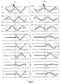
- the current of said phase I A ideally becomes zero downstream of the fault 7 and sees its amplitude increase upstream; however, if the earth fault 7 is very strong, the current variations induced by the fault 7 are very small, up to 20 to 40 times less than the load current, and can be masked by the capacitive currents. As illustrated in figure 2 , a current sensor 12A on the faulty conductor 5A then provides a signal representative of the current I A which does not mark a clear break at the level of the fault 7, because the fault current is low and is hardly noticeable.
- the invention shows that it is possible to overcome this problem of scale by subtracting the load current measured before defect of the fault current I A : as illustrated in FIG. figure 2 , a clear break in the signal provided by the sensor 12A becomes visible. Moreover, the variation of current ⁇ I A in the faulty phase differs according to whether the device according to the invention is disposed upstream 10 i + 1 or downstream 10 i of said sensor 12.
- the correlation coefficients between the different curves are used to determine whether the fault 7 is located upstream or downstream of the sensors 12 supplying signals representative of the currents of the line 5.
- the resemblance between the variation of the homopolar current I 0 and that of the current I A of the faulty phase is important, in contrast to the weak resemblance between the variation of the homopolar current I 0 and that of the currents I B , I C of the other phases; thus, the correlation coefficients normalized with that of the homopolar current I 0 should be, in absolute value, close to unity for phase A and low, for example close to ⁇ 0.1, for the other phases.
- the normalized linear correlation coefficient used in the process according to the invention is preferably obtained by the Bravais-Pearson formula and signed: in fact, the sensors 12 provide an alternating current signal flowing in each of the phases 5A , 5B , C it is preferred to sample so as to obtain a defined number of discrete values representative of the current.
- the number N of values provided by the sampling is adapted to the acquisition duration T acq to optimize the reproducibility and reliability of the results of the Bravais-Pearson formula, that is to say preferably more than 30 values in the case of an acquisition duration T acq equal to a period of the network, with for example a sampling frequency of the order of 1.5 kHz for a 4-phase network at 50 Hz.
- the calculation of the respective variations of the phase currents and of the homopolar current ⁇ I is carried out point by point, with, for each measured value, the subtraction of the value of the load current before defect at the same instant on the sinusoid of the signal. It is preferred not to use a fixed memory window for the reference currents, although this parameter is conventionally used for, for example, measurement and / or qualimetry functions requiring the subtraction of reference values. In fact, most networks 4 have fluctuations in terms of charge and frequency: the frequency of 50 Hz (or 60 Hz) remains the average value with respect to the actual frequency which is not fixed.
- N-point sampling can lead to measurements shifted by a few microseconds on the sinusoid compared to the reference times taken in a fixed window, especially if it is far from the measurement point, which would generate differences in the calculation of the current variation ⁇ I.
- the reference values representative of the charge current just before the fault are thus stored according to the principle of sliding memory, over a window of a duration at least equivalent to T acq : as long as there is no detected fault, the representative values of the signal measured by the sensors 12 replace the first values stored for the same instant on the sinusoid, in order to preserve the samples immediately prior to the fault, which minimizes the possible offsets caused by a fluctuation of the frequency and / or the load.
- the signals representative of the phase currents are acquired over an acquisition period T acq and then sampled; same time, the zero-sequence current I 0 is calculated for the same period, or it can be measured directly via a dedicated core 12.
- the values are stored in an acquisition period T acq in a suitable memory, said storage being slippery, that is, as long as no fault is detected, the last value measured / acquired replaces the previous one.
- the values stored in the memory I 0_MEM , I A_MEM , I B_MEM , I C_MEM are conserved without being replaced, and the signals representative of the phase currents, preferably filtered as before defect, are acquired over an acquisition period T acq , and then sampled; in parallel, the homopolar current I 0 is calculated for the same duration.
- r A , r B , r C Three normalized linear correlation coefficients are thus obtained r A , r B , r C.
- the coefficients A r are closer to 1 or 0.
- the arithmetic mean ⁇ and the standard -type ⁇ of the distribution of the correlation coefficients are used.
- a mean / standard deviation ( ⁇ , ⁇ ) at high average and low standard deviation corresponds to an upstream fault, unlike an average / deviation pair.
- -type ( ⁇ , ⁇ ) with low average and high standard deviation for example ⁇ ⁇ 0.5 and ⁇ > 0.5
- the correlation coefficient is signed here, unlike the one used in the document FR 2 936 319 : the variations due to the fault current are low and the information provided by the sign can not be ignored.
- the comparison according to relation (2), or any directly derived relation thereto is performed and, depending on the result, the directional interpretation L as to the position of the fault is given, either signaled externally, or transmitted to a relay 9 to cut a circuit breaker 6 upstream, or any other use.
- the method according to the invention can be implemented in a protection relay 9, in a fault indicator with warning system, by implementation in a suitable ground fault direction detection device 10.
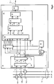
- a device 10 is schematized in figure 4 . It comprises means 14 making it possible to obtain signals representative of the phase currents supplied by suitable sensors 12A, 12B, 12C, for example detection cores, advantageously with filtering by means 16 adapted as an analog filter.
- the filtered I Af , I Bf , I Cf , signals are further conditionned by sampling and the means for obtaining the representative signals 14 comprise a sampling module 18, advantageously operating at more than 1 , 5 kHz, thus providing filtered sampled signals to be processed I Af *, I Bf *, I Cf *.
- the device 10 further comprises means 14 'for obtaining a signal representative of the homopolar current I 0 .
- These means can be coupled directly to a toroid 12 for detecting the current concerned surrounding the line 5 (dashed lines); alternatively, the means 14 'relating to the value of the homopolar current I 0 determine said current by processing the signals relating to the currents of phase I A , I B , I C (not illustrated), advantageously filtered I Af , I Bf , I Cf (not shown), possibly sampled I Af *, I Bf *, I Cf * (solid lines).
- the device 10 further comprises storage means 20 adapted to store in sliding memory on a window of predetermined duration the previous values of the filtered sampled signals of a current of phase I Af *, I Bf *, I Cf * and signal representative of a homopolar current I 0 ; the signals thus stored are stored in the form of reference values I A_MEM , I B_MEM , I C_MEM , I 0_MEM .
- the signals representative of the filtered sampled phase currents I Af *, I Bf *, I Cf * are transmitted to a module processing circuit 30 which comprises a fourth input for the signal representative of the zero sequence current I 0 , four other inputs for the values stored in the storage means 20, and which is activated according to the detection D of a ground fault 10.
- the processing module 30 is connected to any fault detection device, preferably here a module for comparing the zero sequence current I 0 with a detection threshold S d : if the threshold is exceeded, then a fault D is detected and the processing module 30 is activated.
- the processing module 30 successively comprises a computing device 32 for the respective variations of the input signals I Af *, I Bf *, I Cf *, I 0 , with respect to the stored input signals I A_MEM , I B_MEM , I C_MEM , I 0_MEM , a device 34 for calculating normalized correlation coefficients r from the four input signals ⁇ I Af *, ⁇ I Bf *, ⁇ I Cf *, ⁇ I 0 , a computing device 36 of the arithmetic mean ⁇ and of the standard deviation ⁇ of the three data entries r A , r B , r C , a comparison device 38 with two inputs ( ⁇ , ⁇ ) and which is connected to interpretation means 40 whose output is a signal L directional earth fault detection downstream or upstream of the sensors 12 according to the result of the interpretation.
- These means provide at the output the variations of the sampled filtered signals of the phase currents ⁇ I Af *, ⁇ I Bf *, ⁇ I Cf * and the variation of the signal representative of the homopolar current ⁇ I 0 .
- the means for calculating standardized correlated coefficients signed 34 preferably use the Bravais-Pearson formula (1) and are associated with delay means to ensure that the variations of the sampled filtered signals of the phase currents ⁇ I Af * , ⁇ I Bf *, ⁇ I Cf * and the variation of the signal representative of the homopolar current ⁇ I 0 have been acquired over a sufficient period T acq , for example a period of the network 1, or more.
- the comparison means 38 supplying the value to the interpretation module 40 may use different functions.
- the comparison means 38 can include a graphical comparison by two entered values with respect to a half-plane delimited by the half-lines of equation (3); the means 38 can determine the difference between nine eighths of the square of the standard deviation and the square of the average, to compare it to zero; any other option is possible.
- the device 10 of the figure 4 may advantageously be associated with a protection relay 9 for electrical networks, or with a fault-passing indicator for underground medium voltage lines connected in network 1, the output of the interpretation module triggering the breaking of a circuit breaker 6 , lighting a warning light or any other means of security and / or warning.
- a method and a device for directionally detecting a ground fault 7 of a line 5 of a multiphase network 1 have been produced without voltage measurement, which lightens the devices as much as their implementation, for detecting and locating sensitive earth faults on a charged network.
- the embodiment is particularly suitable for the directional detection of a sensitive earth fault, especially when the amplitude of the fault current is less than 10% of the load current, it applies of course in the other cases in place of the process described in FR 2 936 319 although more cumbersome to implement.
- the invention has been described with reference to a three-phase distribution network in which the neutral is grounded by compensated impedance, it is not limited thereto: other types of multiphase networks may be concerned by the invention; in particular, any neutral scheme is appropriate.
- the method according to the invention can use the variation of said current I 0 with respect to its value determined over a prior period: this variant s is particularly interesting in the case of networks having a slight imbalance between phases, whose homopolar current I 0 is therefore non-zero in the off-fault situation.
- the various circuits, modules and functions presented in the context of the preferred embodiment of the invention can be made of analog components, digital or in a programmable form operating with microcontrollers or microprocessors, and the representative signals described may have forms of electrical or electronic signals, data values or information in memories or registers, optical signals viewable in particular on lights or screens, or mechanical signals acting with actuators.
- the current sensors may be different from the described transformers, such as Hall effect sensors or magnetoresistors.
Description
L'invention concerne la détection de défaut sur un réseau électrique de distribution, notamment moyenne tension. En particulier, l'invention propose un principe de détection de défauts résistants entre un conducteur électrique moyenne tension et la terre, défaut par exemple causé par la rupture dudit conducteur, ainsi qu'un dispositif adapté. Des paramètres issus du traitement des seuls signaux représentatifs des courants de chaque phase du réseau permettent la localisation directionnelle, sans utiliser de valeurs représentatives de la tension entre phases, ni de valeurs représentatives des tensions simples.The invention relates to fault detection on an electrical distribution network, in particular medium voltage. In particular, the invention proposes a principle for detecting resistant faults between a medium-voltage electrical conductor and earth, a defect for example caused by the breaking of said conductor, as well as a suitable device. Parameters resulting from the processing of the only signals representative of the currents of each phase of the network allow the directional localization, without using values representing the voltage between phases, nor representative values of the simple voltages.
L'invention concerne également un dispositif de signalisation de défaut et un relai de déclenchement comprenant des capteurs de courant associés à chaque phase du réseau et fournissant au dispositif de détection précédent les signaux permettant la signalisation, par exemple par voyant, ou le déclenchement d'un dispositif de coupure du réseau.The invention also relates to a fault signaling device and a tripping relay comprising current sensors associated with each phase of the network and supplying the preceding detection device with the signals enabling the signaling, for example by light, or the triggering of a cut-off device of the network.
Les dispositifs de détection de défaut à la terre sont notamment utilisés dans les réseaux de distribution électrique triphasés moyenne tension. Tel qu'illustré en
La ligne principale alimente donc des lignes de départ 5, 5', composées de lignes aériennes et/ou de câbles souterrains, dont certaines 5 peuvent comporter en tête un disjoncteur ou autre dispositif de coupure 6 les protégeant. Quelle que soit la solution, le réseau 4 est sujet à des défauts variés, qu'il est important de détecter et localiser afin de pallier les problèmes générés : rupture d'alimentation, dégradation de la tenue des matériels d'isolation, sans compter la sécurité des personnes. Parmi ces défauts, les plus fréquents sont les défauts monophasés 7, localisés hors du poste source, dans lesquels une phase est en contact avec la terre, ou la rupture d'un câble aérien en cas d'intempérie notamment.The main line thus feeds
Ces défauts 7, tout comme les défauts polyphasés qui concernent plusieurs phases, sont de type court-circuit et à l'origine de courants élevés, pouvant atteindre plusieurs milliers ou dizaines de milliers d'ampères, alors que les conducteurs et/ou équipements sont généralement conçus pour supporter quelques centaines d'ampères en fonctionnement nominal.These
Les lignes de départ 5', ou des tronçons de ligne 5, peuvent alors comprendre un dispositif 8 de détection de défaut à la terre. Le dispositif 8 peut servir d'indicateur de passage de défaut, allumant par exemple un voyant lumineux ; un dispositif 81 peut par ailleurs être associé ou intégré à un relai de protection 9 apte à commander l'ouverture des contacts du disjoncteur 6.The starting lines 5 ', or
Une option pour détecter ce type de défaut 7 est de mesurer le courant circulant, ou des paramètres qui lui sont relatifs. Ces mesures sont cependant complétées par des mesures sur les tensions triphasées, si on veut donner la direction relative (amont ou aval) par rapport à l'équipement de détection des défauts. Or, la tension MT du réseau 4 génère une complication dans l'accès aux points de mesure, et des problématiques d'isolement du matériel électronique : ce type de détection directionnelle est difficile à mettre en oeuvre.An option for detecting this type of
Dans le document
Cette solution est cependant inadaptée en cas de courant de charge élevé, notamment lorsque le ratio courant de défaut sur courant de charge est inférieur à 10 %. En particulier, lorsque le défaut est très résistant (par nature du défaut, ou lorsque le sol est résistif par exemple) ou lorsque les courants capacitifs sont faibles, typiquement pour les réseaux à forte proportion d'aérien par rapport au souterrain, la direction donnée peut être erronée. De même, la mise à la terre du secondaire du transformateur 3 peut elle-même être de nature à limiter l'amplitude d'un défaut terre, et la technique précédente est insuffisante. Sur les réseaux de distribution MT, on parle alors de défaut terre résistant (ou terre sensible) lorsque le niveau du courant de défaut est faible (et donc difficilement détectable), soit parce que la résistance de défaut est élevée, soit parce que la mise à la terre du neutre au niveau du transformateur du poste source vient limiter ce courant de défaut (cas d'une bobine de compensation, ou d'un neutre isolé par exemple), soit parce que le sol est lui-même de nature résistive.This solution is, however, unsuitable in the case of a high load current, especially when the current ratio of fault on load current is less than 10%. In particular, when the defect is very resistant (by nature of the defect, or when the ground is resistive for example) or when the capacitive currents are low, typically for the networks with a high proportion of aerial compared to the underground, the given direction can be wrong. Similarly, the earthing of the secondary of the
Des mesures plus fines du courant (« sensitive earth fault ») doivent être réalisées pour ces défauts très résistants, et une détection via la tension est donc mise en oeuvre. Par exemple, le document
La détection et la localisation de ce type de défauts résistifs sur un réseau moyenne tension, notamment dans le cas de ruptures de conducteurs, est peu développée en raison de l'utilisation de mesures complexes à mettre en oeuvre.Detection and localization of this type of resistive fault on a medium voltage network, especially in the case of conductor breaks, is undeveloped because of the use of complex measures to implement.
Une alternative est proposée dans le document
Parmi autres avantages, l'invention vise à pallier des inconvénients des dispositifs et procédés de détection directionnelle de défaut résistant à la terre existants. En particulier, le principe de directionnalité mis en oeuvre repose sur l'analyse de coefficients de corrélation entre les variations du signal représentatif du courant homopolaire et celles des signaux représentatifs des courants de phase, sans utilisation des différentes tensions du réseau, tout en permettant de gérer la détection et la localisation de défauts terre sensible.Among other advantages, the invention aims at overcoming disadvantages of existing earth-resistant defect directional detection devices and methods. In particular, the directionality principle used is based on the analysis of correlation coefficients between the variations of the signal representative of the homopolar current and those of the signals representative of the phase currents, without using the different voltages of the network, while allowing manage the detection and localization of sensitive earth faults.
Sous un de ses aspects, l'invention est relative à un procédé de détection directionnelle de défaut à la terre dans un réseau multiphasé, de préférence triphasé, dans lequel des signaux représentatifs du courant homopolaire et de chacune des phases circulant dans le tronçon de ligne surveillé est mis en mémoire sur une période de stockage prédéterminée, au moins égale à une période du réseau. De préférence, le stockage est réalisé de manière glissante, c'est-à-dire que sur la période de stockage fixée, les dernières valeurs mesurées remplacent les premières valeurs correspondantes au fur et à mesure, de sorte que les valeurs en mémoire sont représentatives du courant de charge au plus près de l'instant de mesure. Avantageusement, les signaux représentatifs des courants de phase sont filtrés, notamment analogiquement, et/ou échantillonnés, de préférence à une fréquence pennettant d'obtenir au moins une trentaine de points sur la durée prédéterminée, par exemple de l'ordre de 1,5 kHz au moins pour un réseau à 50 Hz et une période.In one of its aspects, the invention relates to a directional earth fault detection method in a multiphase network, preferably three-phase, in which signals representative of the zero sequence current and of each of the phases flowing in the line segment. monitored is stored in a predetermined storage period, at least equal to one period of the network. Preferably, the storage is carried out slidably, that is to say that over the fixed storage period, the last measured values replace the first corresponding values as and when, so that the values in memory are representative charging current as close as possible to the measurement time. Advantageously, the signals representative of the phase currents are filtered, in particular analogically, and / or sampled, preferably at a frequency enabling at least thirty points to be obtained over the predetermined duration, for example of the order of 1.5 kHz at least for a 50 Hz network and a period.
Le procédé de détection directionnelle comprend un premier stade de détection du défaut par comparaison d'un signal représentatif du courant homopolaire circulant dans le tronçon de ligne surveillé à un seuil de détection. Le signal représentatif du courant homopolaire peut être obtenu directement, ou par calcul à partir des signaux représentatifs des courants de chaque conducteur de phase dudit tronçon.The directional detection method includes a first fault detection step by comparing a signal representative of the zero sequence current flowing in the monitored line section to a detection threshold. The signal representative of the homopolar current can be obtained directly or by calculation from the signals representative of the currents of each phase conductor of said section.
Si le premier stade détecte la présence d'un défaut à la terre dans ledit tronçon, le stockage des valeurs s'arrête, de sorte que les valeurs mémorisées sont représentatives du courant de charge au moment du défaut, sans avoir été altérées par ce dernier. De plus, le deuxième stade du procédé selon un mode de réalisation préféré de l'invention est déclenché. Le deuxième stade est basé sur le traitement des signaux représentatifs des courants de chaque phase dudit tronçon et du courant de défaut du même tronçon, ces signaux étant obtenus sur une durée prédéterminée suffisante, par exemple un nombre entier de périodes du réseau, inférieur ou égal à la durée de stockage des valeurs mémorisées ; les signaux représentatifs des courants de phase et homopolaire sont obtenus de la même façon que pour la mémorisation, avec mêmes filtrage et échantillonnage.If the first stage detects the presence of a ground fault in said section, the storage of the values stops, so that the stored values are representative of the load current at the time of the fault, without having been altered by the latter. . In addition, the second stage of the method according to a preferred embodiment of the invention is triggered. The second stage is based on the processing of the signals representative of the currents of each phase of said section and of the fault current of the same section, these signals being obtained over a sufficient predetermined duration, for example an integer number of periods of the network, less than or equal to the storage time of the stored values; the signals representative of the phase and homopolar currents are obtained in the same way as for the storage, with the same filtering and sampling.
Après l'acquisition des signaux représentatifs de différents courants, le deuxième stade du procédé se poursuit par un traitement desdits signaux pour permettre d'interpréter si le défaut détecté dans le premier stade se situe en amont ou en aval du point de mesure des courants de phase. Le traitement des signaux comprend, selon l'invention, le calcul de la variation des signaux représentatifs du courant homopolaire de chacun des courants de phase, le calcul des coefficients de corrélation linéaire normalisés entre le signal représentatif de la variation du courant homopolaire du tronçon et chacune des variations des signaux représentatifs des courants de phase ; de préférence, la formule de Bravais-Pearson et/ou des coefficients signés sont utilisés. La dispersion desdits coefficients est ensuite analysée, notamment par le calcul de leur moyenne et de leur écart-type.After the acquisition of signals representative of different currents, the second stage of the process continues with a processing of said signals to allow interpretation of whether the fault detected in the first stage is upstream or downstream of the measurement point of the currents of phase. The signal processing comprises, according to the invention, the calculation of the variation of the signals representative of the homopolar current of each of the phase currents, the calculation of normalized linear correlation coefficients between the signal representative of the variation of the homopolar current of the section and each of the variations of the signals representative of the phase currents; preferably, the Pearson-Bravais formula and / or signed coefficients are used. The dispersion of said coefficients is then analyzed, in particular by calculating their mean and their standard deviation.
De préférence, la dispersion des coefficients est réalisée par formulation d'une relation comparative. En particulier, si la différence entre l'écart-type et la valeur absolue de la moyenne multipliée par deux tiers de la racine carrée de deux est positive, alors le défaut est en aval de la détection ; tout autre comparaison basée sur l'inégalité ![]()
![]()
![]()
![]()
Selon un mode de réalisation préféré du procédé selon l'invention, ledit procédé de détection directionnelle est associé à un actionnement d'un dispositif de coupure pour isoler le tronçon à partir du point en aval duquel un défaut a été détecté.According to a preferred embodiment of the method according to the invention, said directional detection method is associated with an actuation of a cut-off device for isolating the section from the point downstream of which a fault has been detected.
Sous un autre aspect, l'invention se rapporte à un dispositif de détection directionnelle d'un défaut résistant à la terre d'une ligne dans un réseau multiphasé, de préférence triphasé, adapté pour le procédé précédent. Le dispositif de détection directionnelle selon l'invention peut être associé à des capteurs de courant de chacune des phases de la ligne, par exemple des tores de détection, qui lui fournissent les signaux représentatifs desdits courants. Le dispositif de détection directionnelle peut en outre faire partie d'un indicateur de passage de défaut, par exemple par activation de moyens d'alerte de type voyant si un défaut aval aux capteurs est détecté. Dans un mode de réalisation particulièrement préféré, le dispositif de détection directionnelle selon l'invention est associé à un relai de protection de la ligne, les moyens d'alerte provoquant l'actionnement d'un dispositif de coupure de la ligne permettant d'isoler le tronçon sur lequel un défaut a été détecté.In another aspect, the invention relates to a directional detection device for a ground fault of a line in a multiphase network, preferably three-phase, adapted for the above method. The directional detection device according to the invention can be associated with current sensors of each of the phases of the line, for example detection cores, which provide the signals representative of said currents. The directional detection device may furthermore be part of a fault-passing indicator, for example by activating light-type warning means if a defect downstream to the sensors is detected. In a particularly preferred embodiment, the directional detection device according to the invention is associated with a protection relay of the line, the warning means causing the actuation of a cutoff device of the line to isolate the section on which a fault has been detected.
En particulier, le dispositif de détection directionnelle d'un défaut résistant à la terre selon l'invention comprend des premiers moyens pour recevoir des signaux représentatifs de courants de chaque phase de la ligne à surveiller ainsi que des deuxièmes moyens pour recevoir un signal représentatif du courant homopolaire de ladite ligne, ces deuxièmes moyens comprenant de préférence des moyens permettant de déduire des signaux représentatifs des courants de phase, notamment par sommation, ledit signal représentatif du courant homopolaire. Avantageusement, les premiers moyens de réception des signaux représentatifs des courants de phase sont associés à des moyens de filtrage desdits signaux, par exemple un filtre analogique ; de préférence, les premiers moyens comprennent des moyens d'échantillonnage pour obtenir un nombre de valeurs discrètes suffisantes, par exemple à fréquence supérieure à 1,5 kHz.In particular, the directional detection device of an earth-resistant defect according to the invention comprises first means for receiving signals representative of currents of each phase of the line to be monitored as well as second means for receiving a signal representative of the homopolar current of said line, these second means preferably comprising means for deriving signals representative of the phase currents, in particular by summation, said signal representative of the homopolar current. Advantageously, the first signal reception means representative of the phase currents are associated with means for filtering said signals, for example an analog filter; preferably, the first means comprise sampling means to obtain a sufficient number of discrete values, for example at a frequency greater than 1.5 kHz.
Le dispositif selon l'invention comprend en outre des moyens de stockage de valeurs des signaux représentatifs du courant homopolaire et du courant de chacune des phases pendant une durée de stockage prédéterminée, supérieure à une période du réseau et de préférence correspondant à un nombre entier de périodes. Les moyens de stockage sont avantageusement adaptés pour une mémorisation glissante, c'est-à-dire pour stocker les valeurs sur la dernière durée considérée, en remplaçant les premières valeurs stockées par les dernières au fur et à mesure de leur acquisition.The device according to the invention further comprises means for storing values of the signals representative of the homopolar current and the current of each of the phases for a predetermined storage duration, greater than a period of the network and preferably corresponding to an integer of periods. The storage means are advantageously adapted for sliding storage, that is to say for storing the values over the last considered period, by replacing the first values stored by the latter as and when they are acquired.
Le dispositif selon l'invention comprend des moyens de traitement des signaux représentatifs obtenus associés à des moyens d'activation desdits moyens de traitement, les moyens d'activation étant déclenchés par la détection de l'occurrence d'un défaut à la terre. De préférence, la détection de l'occurrence d'un défaut à la terre actionnant les moyens d'activation est réalisée par le dispositif selon l'invention qui comprend des moyens adaptés, notamment des moyens de comparaison du signal représentatif du courant homopolaire à un seuil de détection. La détection de l'occurrence d'un défaut à la terre entraîne également l'arrêt de la mémorisation des données, les moyens de stockage comprenant des moyens de désactivation correspondants, de façon à ce que les valeurs mémorisées concernent l'état du réseau avant occurrence du défaut.The device according to the invention comprises representative signal processing means obtained associated with activation means of said processing means, the activation means being triggered by the detection of the occurrence of a ground fault. Preferably, the detection of the occurrence of a ground fault actuating the activation means is carried out by the device according to the invention which comprises suitable means, in particular means for comparing the signal representative of the homopolar current with a detection limit. The detection of the occurrence of a ground fault also causes stopping of the data storage, the storage means comprising corresponding deactivation means, so that the stored values relate to the state of the front network. occurrence of the defect.
Les moyens de traitement des signaux du dispositif selon l'invention comprennent des moyens pour calculer les coefficients de corrélation linéaire normalisés signés, de préférence selon la formule de Bravais-Pearson, entre le signal représentatif de la variation du courant homopolaire et chacun des signaux représentatifs des variations des courants de phase. Les moyens de calcul sont associés à des moyens de temporisation permettant l'acquisition des signaux pendant une durée correspondant à un nombre entier de périodes du réseau et inférieure, de préférence égale, à la durée de stockage. Les données calculées sont transmises à un module de calcul de la moyenne arithmétique et de l'écart-type, couplé en sortie à des moyens d'interprétation comparant les résultats pour déterminer si le défaut est en amont ou en aval du point d'obtention des signaux représentatif des courants de phase ; les moyens d'interprétation peuvent être du type graphique ou calculatoire.The signal processing means of the device according to the invention comprise means for calculating the normalized linear correlation coefficients signed, preferably according to the Bravais-Pearson formula, between the signal representative of the variation of the zero sequence current and each of the representative signals. variations in phase currents. The calculation means are associated with timing means for acquiring the signals for a duration corresponding to an integer number of periods of the network and less, preferably equal to the storage duration. The calculated data is transmitted to a module for calculating the arithmetic mean and the standard deviation, coupled to output means of interpretation comparing the results to determine whether the defect is upstream or downstream of the point of obtaining signals representative of the phase currents; the means of interpretation may be of the graphical or computational type.
D'autres avantages et caractéristiques ressortiront plus clairement de la description qui suit de modes particuliers de réalisation de l'invention, donnés à titre illustratif et nullement limitatifs, représentés dans les figures annexées.
- La
figure 1 , déjà décrite, représente un réseau électrique dans lequel des dispositifs de détection de défaut terre peuvent être utilisés. - La
figure 2 montre de façon schématique et filtrée des signaux représentatifs des courants de phase et homopolaire, ainsi que leur variation, lors de l'apparition d'un défaut à la terre sur une phase, respectivement à l'amont et à l'aval du dispositif de détection. - La
figure 3 illustre le procédé de détection selon un mode de réalisation préféré de l'invention. - La
figure 4 représente un schéma bloc d'un dispositif de détection de défaut terre selon un mode de réalisation préféré de l'invention.
- The
figure 1 , already described, represents an electrical network in which earth fault detection devices can be used. - The
figure 2 shows schematically and filtered signals representative of the phase and homopolar currents, and their variation, at the occurrence of a ground fault on a phase respectively upstream and downstream of the device of detection. - The
figure 3 illustrates the detection method according to a preferred embodiment of the invention. - The
figure 4 represents a block diagram of a ground fault detection device according to a preferred embodiment of the invention.
Le dispositif 10 de détection directionnelle de défaut 7 selon l'invention peut être utilisé dans tout réseau multiphasé 1, tel que celui décrit en
Lors de l'apparition d'un défaut à la terre 7 sur une des phases A, le courant de ladite phase IA devient idéalement nul en aval du défaut 7 et voit son amplitude augmenter en amont ; cependant, si le défaut à la terre 7 est très résistant, les variations du courant induites par le défaut 7 sont très faibles, jusqu'à 20 à 40 fois moindre que le courant de charge, et peuvent être masquées par les courants capacitifs. Tel qu'illustré en
Cependant, l'invention montre qu'il est possible de s'affranchir de ce problème d'échelle en soustrayant le courant de charge mesuré avant défaut du courant de défaut IA : tel qu'illustré en
La
- le courant I et sa variation du courant ΔI, qui sont ponctuellement altérés dans les deux autres phases B et C, mais dans des proportions moins importantes que dans la phase A ;
- le courant homopolaire I0 détecté sur la
ligne 5, soit parun capteur approprié 12, soit par calcul depuis les trois courants de phase IA, IB, IC obtenus par les capteurs 12A, 12B, 12C, et sa variation.
- the current I and its variation of the current ΔI, which are punctually altered in the other two phases B and C, but in smaller proportions than in phase A;
- the homopolar current I 0 detected on
line 5, either by anappropriate sensor 12, or by calculation from the three phase currents I A , I B , I C obtained by thesensors
Selon l'invention, les coefficients de corrélation entre les différentes courbes sont utilisés pour déterminer si le défaut 7 est localisé en amont ou en aval des capteurs 12 fournissant des signaux représentatifs des courants de la ligne 5. De fait, on y constate que, après occurrence du défaut résistant à la terre, dans le cas d'un défaut 7 ayant lieu en aval du dispositif 10i, la ressemblance entre la variation du courant homopolaire I0 et celle du courant IA de la phase en défaut est importante, au contraire de la ressemblance, faible, entre la variation du courant homopolaire I0 et celle des courants IB, IC des autres phases ; ainsi, les coefficients de corrélation normalisés avec celle du courant homopolaire I0 devraient être, en valeur absolue, proches de l'unité pour la phase A et faibles, par exemple proches de ± 0,1, pour les autres phases. Inversement, dans le cas d'un défaut 7 ayant lieu en amont du dispositif 10i+1, après son occurrence, la ressemblance de la variation du courant homopolaire I0 avec celle du courant IA de la phase en défaut est faible alors que la ressemblance entre la variation du courant homopolaire I0 et celle des courants IB, IC des autres phases reste moyenne ; ainsi, les coefficients de corrélation normalisés signés avec la variation du courant homopolaire I0 devraient rester moyens, par exemple proches de ± 0,5, pour les phases B et C, et être proche de zéro pour la phase A.According to the invention, the correlation coefficients between the different curves are used to determine whether the
Le coefficient de corrélation linéaire normalisé utilisé dans le procédé selon l'invention est de préférence obtenu par la formule de Bravais-Pearson et signé : de fait, les capteurs 12 fournissent un signal de courant alternatif circulant dans chacune des phases 5A, 5B, 5C qu'il est préféré d'échantillonner de façon à obtenir un nombre défini de valeurs discrètes représentatives du courant. Avantageusement, le nombre N de valeurs fourni par l'échantillonnage est adapté à la durée d'acquisition Tacq pour optimiser la reproductibilité et la fiabilité des résultats de la formule de Bravais-Pearson, c'est-à-dire de préférence plus de 30 valeurs dans le cas d'une durée d'acquisition Tacq égale à une période du réseau, avec par exemple une fréquence d'échantillonnage de l'ordre de 1,5 kHz pour un réseau 4 triphasé à 50 Hz.The normalized linear correlation coefficient used in the process according to the invention is preferably obtained by the Bravais-Pearson formula and signed: in fact, the
De la même façon, le calcul des variations respectives des courants de phases et du courant homopolaire ΔI est réalisé point par point, avec, pour chaque valeur mesurée, la soustraction de la valeur du courant de charge avant défaut au même instant sur la sinusoïde du signal. Il est préféré de ne pas utiliser de fenêtre de mémoire fixe pour les courants de référence, bien que ce paramètre soit classiquement utilisé pour, par exemple, les fonctions de mesure et/ou de qualimétrie demandant la soustraction de valeurs de référence. De fait, la plupart des réseaux 4 présentent des fluctuations en termes de charge et de fréquence : la fréquence de 50 Hz (ou 60 Hz) reste la valeur moyenne par rapport à la fréquence réelle qui n'est pas figée. Ainsi, un échantillonnage sur N points peut entraîner des mesures décalées de quelques microsecondes sur la sinusoïde par rapport aux instants de référence pris dans une fenêtre fixe, surtout si elle est éloignée du point de mesure, ce qui génèrerait des écarts sur le calcul de la variation de courant ΔI.In the same way, the calculation of the respective variations of the phase currents and of the homopolar current ΔI is carried out point by point, with, for each measured value, the subtraction of the value of the load current before defect at the same instant on the sinusoid of the signal. It is preferred not to use a fixed memory window for the reference currents, although this parameter is conventionally used for, for example, measurement and / or qualimetry functions requiring the subtraction of reference values. In fact,
Selon l'invention, les valeurs de référence représentatives du courant de charge juste avant défaut sont donc stockées selon le principe de mémoire glissante, sur une fenêtre d'une durée au moins équivalente à Tacq : tant qu'il n'y a pas de défaut détecté, les valeurs représentatives du signal mesurées par les capteurs 12 remplacent les premières valeurs mémorisées pour le même instant sur la sinusoïde, afin de conserver les échantillons immédiatement antérieurs au défaut, ce qui minimise les possibles décalages occasionnés par une fluctuation de la fréquence et/ou de la charge.According to the invention, the reference values representative of the charge current just before the fault are thus stored according to the principle of sliding memory, over a window of a duration at least equivalent to T acq : as long as there is no detected fault, the representative values of the signal measured by the
Ainsi, dans le procédé selon l'invention schématisé en
Une fois le défaut 7 détecté D, par exemple en comparant le courant homopolaire I0 (ou sa variation) à un seuil S0, les valeurs stockées dans la mémoire I0_MEM, IA_MEM, IB_MEM, IC_MEM sont conservées sans plus être remplacées, et les signaux représentatifs des courants de phase, de préférence filtrés comme avant défaut, sont acquis sur une durée d'acquisition Tacq, puis échantillonnés ; parallèlement, le courant homopolaire I0 est calculé pour la même durée. Ces échantillons IAf*, IBf*, ICf*, I0 font ensuite l'objet d'une soustraction terme à terme des valeurs IA_MEM, IB_MEM, IC_MEM, I0_MEM stockées dans la mémoire glissante, afin de déterminer les variations des signaux filtrés échantillonnés des courants de phase et du courant homopolaire. Les coefficients de corrélation signés entre les variations des signaux ΔIAf*, ΔIBf*, ΔICf*, et ΔI0 sont calculés par la formule de Bravais-Pearson selon l'équation (1), dans laquelle rXY désigne l'indice de corrélation linéaire signé entre les deux variables X, Y dont respectivement N valeurs ponctuelles x, y sont connues. 
On obtient ainsi trois coefficients de corrélation linéaire normalisés signés rA, rB, rC. Tel qu'indiqué plus haut, suivant que le défaut 7 est en amont ou en aval, les coefficients rA sont plus proches de 1 ou de 0. Suivant l'invention, pour évaluer cette proximité, la moyenne arithmétique µ et l'écart-type σ de la distribution des coefficients de corrélation sont utilisés. De fait, un couple moyenne/écart-type (µ, σ) à moyenne élevée et écart type faible (par exemple µ > 0,7 et σ < 0,5) correspond à un défaut amont, contrairement à un couple moyenne/écart-type (µ, σ) à moyenne faible et écart type élevé (par exemple µ < 0,5 et σ > 0,5) qui correspond à un défaut aval. A noter que le coefficient de corrélation est ici signé, contrairement à celui utilisé dans le document
Plus particulièrement, on constate que, pour un défaut 7 en aval de la détection 10i, est vérifiée la relation suivante (2), alors que pour un défaut amont 7, 10i+1, l'inverse est vrai, c'est-à-dire : 3 · σ < 2 · √2 · | µ |. 
Dans un procédé préféré selon l'invention, une fois la moyenne et l'écart-type calculés, la comparaison selon la relation (2), ou toute relation qui en dérive directement, est effectuée et, selon le résultat, l'interprétation directionnelle L quant à la position du défaut est donnée, soit signalisée à l'extérieur, soit transmise à un relai 9 pour couper un disjoncteur 6 en amont, ou tout autre utilisation.In a preferred method according to the invention, after calculating the mean and the standard deviation, the comparison according to relation (2), or any directly derived relation thereto, is performed and, depending on the result, the directional interpretation L as to the position of the fault is given, either signaled externally, or transmitted to a
Pour alléger cette étape de calcul du procédé selon l'invention, il est possible graphiquement de déterminer la localisation relative aval ou amont du défaut 7 en positionnant le point de coordonnées (µ,σ) sur un graphe (x,y) où sont tracées deux demi-droites d'équation (3) : si le point est situé dans le demi-plan contenant l'axe des abscisses (x,0), il s'agit d'un défaut amont. 
Le procédé selon l'invention peut être mis en place dans un relai de protection 9, dans un indicateur de défaut avec système d'alerte, par implémentation dans un dispositif de détection directionnelle de défaut à la terre 10 adapté.The method according to the invention can be implemented in a
Un dispositif 10 selon un mode de réalisation préféré de l'invention est schématisé en
Le dispositif 10 selon l'invention comprend en outre des moyens 14' permettant d'obtenir un signal représentatif du courant homopolaire I0. Ces moyens peuvent être couplés directement à un tore 12 de détection du courant concerné entourant la ligne 5 (pointillés) ; alternativement, les moyens 14' relatifs à la valeur du courant homopolaire I0 déterminent ledit courant par traitement des signaux relatifs aux courants de phase IA, IB, IC (non illustré), avantageusement filtrés IAf, IBf, ICf (non illustré), éventuellement échantillonnés IAf*, IBf*, ICf* (traits pleins).The
Le dispositif 10 selon l'invention comprend en outre des moyens de stockage 20 adaptés pour garder en mémoire de manière glissante sur une fenêtre de durée prédéterminée les valeurs précédentes des signaux échantillonnés filtrés d'un courant de phase IAf*, IBf*, ICf* et du signal représentatif d'un courant homopolaire I0 ; les signaux ainsi stockés sont mémorisés sous forme de valeurs de référence IA_MEM, IB_MEM, IC_MEM, I0_MEM.The
Outre leur entrée dans les moyens de détermination 14' du signal représentatif du courant homopolaire I0 et les moyens de stockage 20, les signaux représentatifs des courants de phases échantillonnés filtrés IAf*, IBf*, ICf* sont transmis à un module de traitement 30 qui comprend une quatrième entrée pour le signal représentatif du courant homopolaire I0, quatre autres entrées pour les valeurs mémorisées dans les moyens de stockage 20, et qui est activé en fonction de la détection D d'un défaut à la terre 10. A cette fin, le module de traitement 30 est connecté à un dispositif de détection de défaut 25 quelconque, de préférence ici un module de comparaison du courant homopolaire I0 avec un seuil de détection Sd : si le seuil est dépassé, alors un défaut D est détecté et le module de traitement 30 est activé.In addition to their input into the determination means 14 'of the signal representative of the homopolar current I 0 and the storage means 20, the signals representative of the filtered sampled phase currents I Af *, I Bf *, I Cf * are transmitted to a
Le module de traitement 30 comporte successivement un dispositif de calcul 32 des variations respectives des signaux d'entrée IAf*, IBf*, ICf*, I0, par rapport aux signaux d'entrée mémorisés IA_MEM, IB_MEM, IC_MEM, I0_MEM, un dispositif de calcul 34 de coefficients de corrélation normalisés r à partir des quatre signaux d'entrée ΔIAf*, ΔIBf*, ΔICf*, ΔI0, un dispositif de calcul 36 de la moyenne arithmétique µ et de l'écart-type σ des trois données entrées rA, rB, rC, un dispositif de comparaison 38 avec deux entrées (µ, σ) et qui est relié à des moyens d'interprétation 40 dont la sortie est un signal L de détection directionnelle de défaut terre en aval ou en amont des capteurs 12 selon le résultat de l'interprétation.The
Les moyens de calcul 32 des variations respectives des signaux d'entrée IAf*, IBf*, ICf*. I0, par rapport aux signaux d'entrée mémorisés IA_MEM, IB_MEM, IC_MEM, I0_MEM, réalisent ces différences terme à terme pour chaque échantillon de la fenêtre de durée d'acquisition Tacq. Ces moyens fournissent en sortie les variations des signaux filtrés échantillonnés des courants de phase ΔIAf*, ΔIBf*, ΔICf* et la variation du signal représentatif du courant homopolaire ΔI0.The calculation means 32 of the respective variations of the input signals I Af *, I Bf *, I Cf *. I 0 , with respect to the stored input signals I A_MEM , I B_MEM , I C_MEM , I 0_MEM , make these differences term by term for each sample of the acquisition duration window T acq . These means provide at the output the variations of the sampled filtered signals of the phase currents ΔI Af *, ΔI Bf *, ΔI Cf * and the variation of the signal representative of the homopolar current ΔI 0 .
Les moyens de calcul de coefficients de corrélation normalisés signés 34 utilisent de préférence la formule (1) de Bravais-Pearson et sont associés à des moyens de temporisation afin de s'assurer que les variations des signaux filtrés échantillonnés des courants de phase ΔIAf*, ΔIBf*, ΔICf* et la variation du signal représentatif du courant homopolaire ΔI0 ont été acquises sur une durée suffisante Tacq, par exemple une période du réseau 1, voire plus.The means for calculating standardized correlated coefficients signed 34 preferably use the Bravais-Pearson formula (1) and are associated with delay means to ensure that the variations of the sampled filtered signals of the phase currents ΔI Af * , ΔI Bf *, ΔI Cf * and the variation of the signal representative of the homopolar current ΔI 0 have been acquired over a sufficient period T acq , for example a period of the
Les moyens de comparaison 38 fournissant la valeur au module d'interprétation 40 peuvent utiliser différentes fonctions. En particulier, les moyens de comparaison 38 peuvent comprendre une comparaison graphique par des deux valeurs entrées par rapport à un demi-plan délimité par les demi-droites d'équation (3) ; les moyens 38 peuvent déterminer la différence entre neuf huitièmes du carré de l'écart-type et le carré de la moyenne, pour la comparer à zéro ; toute autre option est possible.The comparison means 38 supplying the value to the
Le dispositif 10 de la
Ainsi, selon l'invention, un procédé et un dispositif de détection directionnelle 10 d'un défaut à la terre 7 d'une ligne 5 d'un réseau multiphasé 1 ont été réalisés sans mesure de tension, ce qui allège autant les dispositifs que leur mise en oeuvre, permettant de détecter et localiser des défauts terre sensibles sur un réseau chargé. De fait, bien que le mode de réalisation soit particulièrement adapté pour la détection directionnelle d'un défaut terre sensible, notamment lorsque l'amplitude du courant de défaut est inférieure à 10 % du courant de charge, elle s'applique bien entendu dans les autres cas en lieu et place du procédé décrit dans
Bien que l'invention ait été décrite en référence à un réseau de distribution triphasé dans lequel le neutre est mis à la terre par impédance compensée, elle ne s'y limite pas : d'autres types de réseaux multiphasés peuvent être concernés par l'invention ; en particulier, tout régime de neutre est approprié. Par ailleurs, bien que décrit avec détermination et traitement du courant homopolaire instantané I0 pour la détection du défaut, le procédé selon l'invention peut utiliser la variation dudit courant I0 par rapport à sa valeur déterminée sur une période préalable : cette variante s'avère particulièrement intéressante dans le cas de réseaux présentant un léger déséquilibre entre phases, dont le courant homopolaire I0 est donc non nul en situation hors défaut.Although the invention has been described with reference to a three-phase distribution network in which the neutral is grounded by compensated impedance, it is not limited thereto: other types of multiphase networks may be concerned by the invention; in particular, any neutral scheme is appropriate. Furthermore, although described with determination and treatment of the instantaneous zero current I 0 for the detection of the fault, the method according to the invention can use the variation of said current I 0 with respect to its value determined over a prior period: this variant s is particularly interesting in the case of networks having a slight imbalance between phases, whose homopolar current I 0 is therefore non-zero in the off-fault situation.
De fait, les différents circuits, modules et fonctions présentés dans le cadre du mode de réalisation préféré de l'invention peuvent être réalisés en composants analogiques, numériques ou sous une forme programmable opérant avec des microcontrôleurs ou des microprocesseurs, et les signaux représentatifs décrits peuvent avoir des formes de signaux électriques ou électroniques, de valeurs de données ou d'information dans des mémoires ou des registres, de signaux optiques visualisables notamment sur des voyants ou des écrans, ou de signaux mécaniques agissant avec des actionneurs. De même, les capteurs de courant peuvent être différents des transformateurs décrits, comme des capteurs à effet Hall ou des magnétorésistances.In fact, the various circuits, modules and functions presented in the context of the preferred embodiment of the invention can be made of analog components, digital or in a programmable form operating with microcontrollers or microprocessors, and the representative signals described may have forms of electrical or electronic signals, data values or information in memories or registers, optical signals viewable in particular on lights or screens, or mechanical signals acting with actuators. Similarly, the current sensors may be different from the described transformers, such as Hall effect sensors or magnetoresistors.
Claims (15)
- Device (10) for directional detection of an earth fault (7) in a multiphase network comprising:- first means (14) for receiving signals representative of the current (IA, IB, IC) of each of the phases;- second means (14') for receiving a signal representative of the homopolar current (I0) of all the phases;- processing means (30) for processing the signals representative of current, comprising means (34) for calculating normalized correlation coefficients (rA, rB, rC) and means (36) for calculating the mean (µ) and standard deviation (σ) of the calculated correlation coefficients;- means for activating said processing means (30) depending on a detection signal (D) of the occurrence of an earth fault in the network (I);- means for interpreting results of the processing of the signals comprising means for comparing said mean (µ) and said standard deviation (σ) in order to determine whether the fault is upstream or downstream of the device (10);characterized in that the device (10) furthermore comprises storage means (20) for storing values of the signals representative of the homopolar current and of the current of each of the phases (I0_MEM, IA_MEM, IB_MEM, IC_MEM) over a storage duration (Tacq) prior to the detection signal (D) of the occurrence of an earth fault (7), and the processing means (30) comprise means for determining the variation of the signal representative of the homopolar current and of the current of each of the phases (ΔI0, ΔIA, ΔIB, ΔIC) with respect to the stored values (I0_MEM, IA_MEM, IB_MEM, IC_MEM) over a predetermined duration smaller than or equal to the storage duration, the means for calculating normalized correlation coefficients (34) being suitable for calculating correlation coefficients (rA, rB, rC) between the variation of the signal representative of the homopolar current (ΔI0) and the variation of each of the signals representative of the phase current (ΔIA, ΔIB, ΔIC).
- Directional detection device (10) according to Claim 1, in which the storage duration corresponds to a whole number of periods of the network (1) and the determined duration is equal to the duration of storage (Tacq).
- Detection device according to either of Claims 1 and 2, in which the storage means (20) are suitable for storing the values over a rolling period and comprise means for deactivating depending on a detection signal (D) of the occurrence of an earth fault in the network (1).
- Directional detection device (10) according to one of Claims 1 to 3, furthermore comprising means (18) for detecting the occurrence of an earth fault in the network, which means are linked to the means for activating the processing means (30) and to the storage means (20), comprising a comparator for comparing the signal representative of the homopolar current (l0) with a threshold of detection (S0).
- Directional detection device (10) according to one of Claims 1 to 4, in which the first means (14) for receiving signals representative of the currents of each phase (IA, IB, IC) comprise sampling means (18) suitable for supplying a sufficient number of values over the predetermined duration and the storage duration (Tacq).
- Earth-fault occurrence indicator comprising current sensors (12A, 12B, 12C) arranged on each phase conductor (5A, 5B, 5C) of an electrical network (1) to be monitored and comprising a device for directional fault detection (10) according to one of Claims 1 to 5, connected to said current sensors (12A, 12B, 12C) for receiving the signals representative of phase current (IA, IB, IC).
- Earth protection relay (9) comprising at least one fault indicator according to Claim 6 and means for actuating a switching device (6) depending on the results of the interpreting means (40) of the directional detection device (10) of the indicator.
- Method for directional detection (D, L) of an earth fault (7) in a multiphase network (1) in which signals representative of the homopolar current (I0_MEM) and of each of the phase currents (IA_MEM, IB_MEM, IC_MEM) are memorized over a duration (Tacq) of at least one period of the network, comprising the triggering, following the obtention of a signal (D) indicative of the presence of said earth fault (10), of the directional determination (L) of the fault (10), said directional determination comprising the successive steps of:- obtaining signals representative of each of the phase currents (IA, IB, IC) over a predetermined duration (Tacq) shorter than or equal to the duration of memorization;- obtaining a signal representative of the homopolar current (l0) flowing in the network over the same predetermined duration (Tacq);- processing the signals representative of the phase currents and the earth fault current (I0, IA, IB, IC);- interpreting the results of the processing of the signals in order to indicate whether the detected fault (D) is situated upstream or downstream of the location at which the signals representative of the phase currents (IA, IB, IC) were obtained;characterized in that said step of processing the signals comprises:- calculating the variation of the homopolar current (l0) and of each of the phase currents (IA, IB, IC) over the predetermined duration (Tacq) with respect to the memorized values (I0_MEM, IA_MEM, IB_MEM, IC_MEM);- calculating the normalized correlation coefficients (rA, rB, rC) between the variations of the homopolar current signal (ΔI0) and of each of the phase current signals (ΔIA, ΔIB, ΔIC) over the predetermined duration (Tacq);- calculating the arithmetic mean (µ) and the standard deviation (σ) of said correlation coefficients (rA, rB, rC);- said interpretation being carried out by a comparison employing said mean (µ) and said standard deviation (σ).
- Directional detection method according to Claim 8, in which the representative values (I0_MEM, IA_MEM, IB_MEM, IC_MEM) are memorized in a rolling manner as long as the signal indicative of the presence of the fault (D) is not obtained.
- Directional detection method according to Claim 8 or 9, in which the signal (D) indicative of the presence of an earth fault (7) is obtained via the reception of a signal representative of the homopolar current (l0) flowing in the network (1) and the result of a comparison of the homopolar current signal (l0) with a fault detection threshold (S0).
- Directional detection method according to one of Claims 8 to 10, in which the interpretation step comprises comparing, with zero, the difference between the square of three times the standard deviation (σ) and eight times the square of the mean (µ).
- Directional detection method according to one of Claims 8 to 10, in which the interpretation step comprises graphical comparison of the mean (µ) and standard deviation (σ) with two half-lines of equation

- Directional detection method according to one of Claims 8 to 12, in which the step for providing the signals representative of the phase currents (IA, IB, IC) comprises sampling the current at a frequency higher than 1.5 kHz.
- Directional detection method according to one of Claims 8 to 13, in which the normalized correlation coefficients (rA, rB, rC) are calculated according to the Bravais-Pearson formula.
- Method for protecting a power line (5) during the occurrence of an earth fault (7) comprising actuating a breaking device (6) of said line (5) if an earth fault (7) has been detected by a method according one of Claims 8 to 14 downstream of said breaking device (6).
Applications Claiming Priority (1)
| Application Number | Priority Date | Filing Date | Title |
|---|---|---|---|
| FR1257023A FR2993670B1 (en) | 2012-07-20 | 2012-07-20 | DIRECTIONAL DETECTION OF SENSITIVE LAND DEFECT MEDIUM VOLTAGE BY LINEAR CORRELATION |
Publications (2)
| Publication Number | Publication Date |
|---|---|
| EP2687860A1 EP2687860A1 (en) | 2014-01-22 |
| EP2687860B1 true EP2687860B1 (en) | 2016-03-23 |
Family
ID=47191891
Family Applications (1)
| Application Number | Title | Priority Date | Filing Date |
|---|---|---|---|
| EP13172415.5A Active EP2687860B1 (en) | 2012-07-20 | 2013-06-18 | Directional detection of a sensitive medium-voltage earth fault by linear correlation |
Country Status (5)
| Country | Link |
|---|---|
| EP (1) | EP2687860B1 (en) |
| CN (1) | CN103576045B (en) |
| ES (1) | ES2569080T3 (en) |
| FR (1) | FR2993670B1 (en) |
| RU (1) | RU2631025C2 (en) |
Families Citing this family (13)
| Publication number | Priority date | Publication date | Assignee | Title |
|---|---|---|---|---|
| FR3023429A1 (en) | 2014-07-02 | 2016-01-08 | Schneider Electric Ind Sas | MODULAR TELE-CONDUCT EQUIPMENT |
| FR3023444B1 (en) | 2014-07-02 | 2018-02-16 | Schneider Electric Industries Sas | POWER MODULE FOR MODULAR TELE-DRIVING EQUIPMENT AND EQUIPMENT COMPRISING IT |
| ES2537131B2 (en) * | 2014-12-23 | 2016-10-07 | Universidad Politécnica de Madrid | Method and directional system for detecting ground defects in DC networks of insulated cables |
| CN105807174B (en) * | 2014-12-30 | 2019-02-15 | 施耐德电器工业公司 | Current transformer disconnection detection method in electrical power trans mission/distribution system protection |
| US9829519B2 (en) * | 2015-05-27 | 2017-11-28 | Eaton Corporation | Method and apparatus to commission voltage sensors and branch circuit current sensors for branch circuit monitoring systems |
| US9897647B2 (en) * | 2015-05-27 | 2018-02-20 | Eaton Corporation | Method and apparatus to commission voltage sensors and branch circuit current sensors for branch circuit monitoring systems |
| FI126892B (en) * | 2016-05-23 | 2017-07-31 | Emtele Oy | Felströmindikator |
| EP3566065B1 (en) * | 2017-01-06 | 2023-03-22 | Vertiv Corporation | System and method of identifying path of residual current flow through an intelligent power strip |
| CN112119556B (en) * | 2018-05-18 | 2023-01-24 | Abb瑞士股份有限公司 | Method and apparatus for use in ground fault protection |
| EP3570400B1 (en) | 2018-05-18 | 2022-01-26 | ABB Schweiz AG | Method and apparatus for use in earth-fault protection |
| CN109188177B (en) * | 2018-10-01 | 2023-12-19 | 江苏国传电气有限公司 | High-power NPC three-level inverter short-circuit current on-line detection system |
| CN110927516B (en) * | 2019-11-14 | 2022-01-21 | 长沙理工大学 | Power distribution network single-phase earth fault identification method and system based on grounding transformer tap grounding |
| CN112415327B (en) * | 2020-10-22 | 2022-04-15 | 中国矿业大学 | Cable distribution network fault section identification method based on grounding wire current direction difference |
Family Cites Families (13)
| Publication number | Priority date | Publication date | Assignee | Title |
|---|---|---|---|---|
| RU95102709A (en) * | 1995-02-23 | 1996-11-27 | Дагестанский Политехнический Институт | Method to determine direction of fault to earth in aerial distribution networks |
| JP3384481B2 (en) * | 1997-02-24 | 2003-03-10 | 東光電気株式会社 | Ground fault detector for high voltage distribution lines |
| US6584417B1 (en) * | 1999-10-22 | 2003-06-24 | Abb Inc. | Method and directional element for fault direction determination in a capacitance-compensated line |
| SI21482A (en) | 2004-06-01 | 2004-10-31 | Marjan Bezjak | Device for detecting and shutdown of an interrupted semi-insulated conductor in medium voltage power lines |
| RU2006101433A (en) * | 2006-01-18 | 2007-07-27 | ООО "Электроавтоматика" (RU) | METHOD FOR DETERMINING THE EARTH CLOSING DIRECTION |
| FR2936319B1 (en) * | 2008-09-25 | 2010-09-10 | Schneider Electric Ind Sas | DIRECTIONAL DETECTION OF A FAULT TO EARTH BY LINEAR CORRELATION |
| EP2169799B1 (en) * | 2008-09-25 | 2019-09-04 | Schneider Electric Industries SAS | Directional detection of a ground fault |
| CN101539607B (en) * | 2009-04-09 | 2011-10-26 | 北京市天利自动化设备研究所 | Method for grounding and selecting lines of low-current grounding system and device |
| CN101858948B (en) * | 2009-04-10 | 2015-01-28 | 阿海珐输配电英国有限公司 | Method and system for carrying out transient and intermittent earth fault detection and direction determination in three-phase medium-voltage distribution system |
| EP2278676A1 (en) * | 2009-07-24 | 2011-01-26 | ABB Technology AG | Fault direction indicator device and related methods |
| FR2963967B1 (en) * | 2010-08-20 | 2012-08-17 | Schneider Electric Ind Sas | DIRECTIONAL DETECTION OF EARTH FAULT WITH SINGLE SENSOR |
| FR2976363B1 (en) | 2011-06-07 | 2013-05-24 | Schneider Electric Ind Sas | DIRECTIONAL DETECTION OF RESISTANT LAND FAULT AND MEDIUM VOLTAGE CONDUCTOR BREAK |
| CN102435896B (en) * | 2011-09-07 | 2014-01-15 | 中国人民解放军海军工程大学 | Intermittent grounding fault rapid identification method of ship medium-voltage power system |
-
2012
- 2012-07-20 FR FR1257023A patent/FR2993670B1/en not_active Expired - Fee Related
-
2013
- 2013-06-18 ES ES13172415.5T patent/ES2569080T3/en active Active
- 2013-06-18 EP EP13172415.5A patent/EP2687860B1/en active Active
- 2013-07-19 CN CN201310305593.8A patent/CN103576045B/en active Active
- 2013-07-19 RU RU2013133963A patent/RU2631025C2/en active
Also Published As
| Publication number | Publication date |
|---|---|
| CN103576045A (en) | 2014-02-12 |
| EP2687860A1 (en) | 2014-01-22 |
| ES2569080T3 (en) | 2016-05-06 |
| CN103576045B (en) | 2017-06-23 |
| RU2013133963A (en) | 2015-01-27 |
| FR2993670A1 (en) | 2014-01-24 |
| FR2993670B1 (en) | 2014-07-11 |
| RU2631025C2 (en) | 2017-09-15 |
Similar Documents
| Publication | Publication Date | Title |
|---|---|---|
| EP2687860B1 (en) | Directional detection of a sensitive medium-voltage earth fault by linear correlation | |
| EP2741390A1 (en) | Directional detection of a fault, in particular in a network with compensated or insulated neutral | |
| EP2169799A2 (en) | Directional detection of a ground fault | |
| EP2383856B1 (en) | Identification and directional detection of a defect in a three-phase network | |
| EP2421110B1 (en) | Directional detection of an earth fault with a single sensor | |
| EP1890165B1 (en) | Method of directional detection of a fault in the ground connection and device for implementing the same | |
| EP2533060B1 (en) | Directional detection of resistive earth fault and medium-voltage conductor breakage | |
| FR2936319A1 (en) | Current line ground fault directional-detection device for three-phase network in ground protection relay, has calculation device to calculate average and standard deviation, and comparison device to compare average and deviation | |
| EP3001524A1 (en) | Directional detection of a ground fault in an electrical distribution network | |
| EP3814788A1 (en) | System and method for fault localisation on a polyphase power system using the evolution of forward and reverse voltage | |
| EP3106887B1 (en) | Method and device for detecting a fault in an electrical network | |
| FR2936378A1 (en) | Directional detection device for ground fault passage indicator of power line protection relay, has interpretation unit to interpret signal processing results, and comprising comparison unit to compare norm average with norms of phases | |
| EP0537066B1 (en) | Method for the selective detection of resistive defects in power-distribution networks | |
| EP2910958A1 (en) | Detecting a fault, in particular a transient fault, in an electrical network | |
| EP3583432B1 (en) | Method for verifying the wiring of a meter | |
| EP3879288B1 (en) | Method for testing capacitive current cut-off of a circuit breaker | |
| FR2999294A1 (en) | Detection device for directional detection of ground fault in e.g. insulated neutral balanced three-phase network, has location module including evaluation unit of phase shift between homopolar voltage and homopolar current derivative | |
| FR2999295A1 (en) | Detection device for directional detection of ground fault in e.g. insulated neutral balanced three-phase network, has location module including evaluation unit of phase shift between homopolar voltage and homopolar current derivative | |
| WO2001096889A1 (en) | Method for detecting resistive faults | |
| EP3798648A1 (en) | Method for determining the position of a fault precursor in a high-voltage cable in operation | |
| EP1083644B1 (en) | Earth fault protection device sensitive to arc currents, trip device and circuit breaker comprising such a device | |
| FR2756051A1 (en) | DEVICE AND METHOD FOR ANALYZING FAULTS ON ELECTRICAL DISTRIBUTION NETWORKS | |
| EP4300112A1 (en) | Detection of loss of neutral | |
| EP3033760A1 (en) | Method, device and computer program for controlling a mechatronic circuit breaker | |
| WO2022084595A1 (en) | Method for detecting a fault of a battery module group |
Legal Events
| Date | Code | Title | Description |
|---|---|---|---|
| PUAI | Public reference made under article 153(3) epc to a published international application that has entered the european phase |
Free format text: ORIGINAL CODE: 0009012 |
|
| AK | Designated contracting states |
Kind code of ref document: A1 Designated state(s): AL AT BE BG CH CY CZ DE DK EE ES FI FR GB GR HR HU IE IS IT LI LT LU LV MC MK MT NL NO PL PT RO RS SE SI SK SM TR |
|
| AX | Request for extension of the european patent |
Extension state: BA ME |
|
| 17P | Request for examination filed |
Effective date: 20140204 |
|
| RBV | Designated contracting states (corrected) |
Designated state(s): AL AT BE BG CH CY CZ DE DK EE ES FI FR GB GR HR HU IE IS IT LI LT LU LV MC MK MT NL NO PL PT RO RS SE SI SK SM TR |
|
| GRAP | Despatch of communication of intention to grant a patent |
Free format text: ORIGINAL CODE: EPIDOSNIGR1 |
|
| INTG | Intention to grant announced |
Effective date: 20151204 |
|
| GRAS | Grant fee paid |
Free format text: ORIGINAL CODE: EPIDOSNIGR3 |
|
| GRAA | (expected) grant |
Free format text: ORIGINAL CODE: 0009210 |
|
| AK | Designated contracting states |
Kind code of ref document: B1 Designated state(s): AL AT BE BG CH CY CZ DE DK EE ES FI FR GB GR HR HU IE IS IT LI LT LU LV MC MK MT NL NO PL PT RO RS SE SI SK SM TR |
|
| REG | Reference to a national code |
Ref country code: GB Ref legal event code: FG4D Free format text: NOT ENGLISH |
|
| REG | Reference to a national code |
Ref country code: CH Ref legal event code: EP |
|
| REG | Reference to a national code |
Ref country code: AT Ref legal event code: REF Ref document number: 783679 Country of ref document: AT Kind code of ref document: T Effective date: 20160415 |
|
| REG | Reference to a national code |
Ref country code: IE Ref legal event code: FG4D Free format text: LANGUAGE OF EP DOCUMENT: FRENCH |
|
| REG | Reference to a national code |
Ref country code: DE Ref legal event code: R096 Ref document number: 602013005649 Country of ref document: DE |
|
| REG | Reference to a national code |
Ref country code: ES Ref legal event code: FG2A Ref document number: 2569080 Country of ref document: ES Kind code of ref document: T3 Effective date: 20160506 |
|
| REG | Reference to a national code |
Ref country code: FR Ref legal event code: PLFP Year of fee payment: 4 |
|
| REG | Reference to a national code |
Ref country code: LT Ref legal event code: MG4D |
|
| REG | Reference to a national code |
Ref country code: NL Ref legal event code: MP Effective date: 20160323 |
|
| PG25 | Lapsed in a contracting state [announced via postgrant information from national office to epo] |
Ref country code: NO Free format text: LAPSE BECAUSE OF FAILURE TO SUBMIT A TRANSLATION OF THE DESCRIPTION OR TO PAY THE FEE WITHIN THE PRESCRIBED TIME-LIMIT Effective date: 20160623 Ref country code: GR Free format text: LAPSE BECAUSE OF FAILURE TO SUBMIT A TRANSLATION OF THE DESCRIPTION OR TO PAY THE FEE WITHIN THE PRESCRIBED TIME-LIMIT Effective date: 20160624 Ref country code: HR Free format text: LAPSE BECAUSE OF FAILURE TO SUBMIT A TRANSLATION OF THE DESCRIPTION OR TO PAY THE FEE WITHIN THE PRESCRIBED TIME-LIMIT Effective date: 20160323 Ref country code: FI Free format text: LAPSE BECAUSE OF FAILURE TO SUBMIT A TRANSLATION OF THE DESCRIPTION OR TO PAY THE FEE WITHIN THE PRESCRIBED TIME-LIMIT Effective date: 20160323 |
|
| REG | Reference to a national code |
Ref country code: AT Ref legal event code: MK05 Ref document number: 783679 Country of ref document: AT Kind code of ref document: T Effective date: 20160323 |
|
| PG25 | Lapsed in a contracting state [announced via postgrant information from national office to epo] |
Ref country code: LV Free format text: LAPSE BECAUSE OF FAILURE TO SUBMIT A TRANSLATION OF THE DESCRIPTION OR TO PAY THE FEE WITHIN THE PRESCRIBED TIME-LIMIT Effective date: 20160323 Ref country code: RS Free format text: LAPSE BECAUSE OF FAILURE TO SUBMIT A TRANSLATION OF THE DESCRIPTION OR TO PAY THE FEE WITHIN THE PRESCRIBED TIME-LIMIT Effective date: 20160323 Ref country code: SE Free format text: LAPSE BECAUSE OF FAILURE TO SUBMIT A TRANSLATION OF THE DESCRIPTION OR TO PAY THE FEE WITHIN THE PRESCRIBED TIME-LIMIT Effective date: 20160323 Ref country code: NL Free format text: LAPSE BECAUSE OF FAILURE TO SUBMIT A TRANSLATION OF THE DESCRIPTION OR TO PAY THE FEE WITHIN THE PRESCRIBED TIME-LIMIT Effective date: 20160323 Ref country code: LT Free format text: LAPSE BECAUSE OF FAILURE TO SUBMIT A TRANSLATION OF THE DESCRIPTION OR TO PAY THE FEE WITHIN THE PRESCRIBED TIME-LIMIT Effective date: 20160323 |
|
| PG25 | Lapsed in a contracting state [announced via postgrant information from national office to epo] |
Ref country code: PL Free format text: LAPSE BECAUSE OF FAILURE TO SUBMIT A TRANSLATION OF THE DESCRIPTION OR TO PAY THE FEE WITHIN THE PRESCRIBED TIME-LIMIT Effective date: 20160323 Ref country code: IS Free format text: LAPSE BECAUSE OF FAILURE TO SUBMIT A TRANSLATION OF THE DESCRIPTION OR TO PAY THE FEE WITHIN THE PRESCRIBED TIME-LIMIT Effective date: 20160723 Ref country code: EE Free format text: LAPSE BECAUSE OF FAILURE TO SUBMIT A TRANSLATION OF THE DESCRIPTION OR TO PAY THE FEE WITHIN THE PRESCRIBED TIME-LIMIT Effective date: 20160323 |
|
| PG25 | Lapsed in a contracting state [announced via postgrant information from national office to epo] |
Ref country code: SM Free format text: LAPSE BECAUSE OF FAILURE TO SUBMIT A TRANSLATION OF THE DESCRIPTION OR TO PAY THE FEE WITHIN THE PRESCRIBED TIME-LIMIT Effective date: 20160323 Ref country code: AT Free format text: LAPSE BECAUSE OF FAILURE TO SUBMIT A TRANSLATION OF THE DESCRIPTION OR TO PAY THE FEE WITHIN THE PRESCRIBED TIME-LIMIT Effective date: 20160323 Ref country code: PT Free format text: LAPSE BECAUSE OF FAILURE TO SUBMIT A TRANSLATION OF THE DESCRIPTION OR TO PAY THE FEE WITHIN THE PRESCRIBED TIME-LIMIT Effective date: 20160725 Ref country code: CZ Free format text: LAPSE BECAUSE OF FAILURE TO SUBMIT A TRANSLATION OF THE DESCRIPTION OR TO PAY THE FEE WITHIN THE PRESCRIBED TIME-LIMIT Effective date: 20160323 Ref country code: SK Free format text: LAPSE BECAUSE OF FAILURE TO SUBMIT A TRANSLATION OF THE DESCRIPTION OR TO PAY THE FEE WITHIN THE PRESCRIBED TIME-LIMIT Effective date: 20160323 Ref country code: RO Free format text: LAPSE BECAUSE OF FAILURE TO SUBMIT A TRANSLATION OF THE DESCRIPTION OR TO PAY THE FEE WITHIN THE PRESCRIBED TIME-LIMIT Effective date: 20160323 |
|
| PG25 | Lapsed in a contracting state [announced via postgrant information from national office to epo] |
Ref country code: BE Free format text: LAPSE BECAUSE OF NON-PAYMENT OF DUE FEES Effective date: 20160630 |
|
| REG | Reference to a national code |
Ref country code: DE Ref legal event code: R097 Ref document number: 602013005649 Country of ref document: DE |
|
| PLBE | No opposition filed within time limit |
Free format text: ORIGINAL CODE: 0009261 |
|
| STAA | Information on the status of an ep patent application or granted ep patent |
Free format text: STATUS: NO OPPOSITION FILED WITHIN TIME LIMIT |
|
| PG25 | Lapsed in a contracting state [announced via postgrant information from national office to epo] |
Ref country code: MC Free format text: LAPSE BECAUSE OF FAILURE TO SUBMIT A TRANSLATION OF THE DESCRIPTION OR TO PAY THE FEE WITHIN THE PRESCRIBED TIME-LIMIT Effective date: 20160323 Ref country code: DK Free format text: LAPSE BECAUSE OF FAILURE TO SUBMIT A TRANSLATION OF THE DESCRIPTION OR TO PAY THE FEE WITHIN THE PRESCRIBED TIME-LIMIT Effective date: 20160323 |
|
| REG | Reference to a national code |
Ref country code: CH Ref legal event code: PL |
|
| PG25 | Lapsed in a contracting state [announced via postgrant information from national office to epo] |
Ref country code: BG Free format text: LAPSE BECAUSE OF FAILURE TO SUBMIT A TRANSLATION OF THE DESCRIPTION OR TO PAY THE FEE WITHIN THE PRESCRIBED TIME-LIMIT Effective date: 20160623 |
|
| 26N | No opposition filed |
Effective date: 20170102 |
|
| REG | Reference to a national code |
Ref country code: IE Ref legal event code: MM4A |
|
| PG25 | Lapsed in a contracting state [announced via postgrant information from national office to epo] |
Ref country code: CH Free format text: LAPSE BECAUSE OF NON-PAYMENT OF DUE FEES Effective date: 20160630 Ref country code: LI Free format text: LAPSE BECAUSE OF NON-PAYMENT OF DUE FEES Effective date: 20160630 |
|
| PG25 | Lapsed in a contracting state [announced via postgrant information from national office to epo] |
Ref country code: IE Free format text: LAPSE BECAUSE OF NON-PAYMENT OF DUE FEES Effective date: 20160618 Ref country code: SI Free format text: LAPSE BECAUSE OF FAILURE TO SUBMIT A TRANSLATION OF THE DESCRIPTION OR TO PAY THE FEE WITHIN THE PRESCRIBED TIME-LIMIT Effective date: 20160323 |
|
| REG | Reference to a national code |
Ref country code: FR Ref legal event code: PLFP Year of fee payment: 5 |
|
| PG25 | Lapsed in a contracting state [announced via postgrant information from national office to epo] |
Ref country code: HU Free format text: LAPSE BECAUSE OF FAILURE TO SUBMIT A TRANSLATION OF THE DESCRIPTION OR TO PAY THE FEE WITHIN THE PRESCRIBED TIME-LIMIT; INVALID AB INITIO Effective date: 20130618 Ref country code: CY Free format text: LAPSE BECAUSE OF FAILURE TO SUBMIT A TRANSLATION OF THE DESCRIPTION OR TO PAY THE FEE WITHIN THE PRESCRIBED TIME-LIMIT Effective date: 20160323 |
|
| REG | Reference to a national code |
Ref country code: FR Ref legal event code: PLFP Year of fee payment: 6 |
|
| PG25 | Lapsed in a contracting state [announced via postgrant information from national office to epo] |
Ref country code: MT Free format text: LAPSE BECAUSE OF FAILURE TO SUBMIT A TRANSLATION OF THE DESCRIPTION OR TO PAY THE FEE WITHIN THE PRESCRIBED TIME-LIMIT Effective date: 20160323 Ref country code: TR Free format text: LAPSE BECAUSE OF FAILURE TO SUBMIT A TRANSLATION OF THE DESCRIPTION OR TO PAY THE FEE WITHIN THE PRESCRIBED TIME-LIMIT Effective date: 20160323 Ref country code: LU Free format text: LAPSE BECAUSE OF NON-PAYMENT OF DUE FEES Effective date: 20160618 Ref country code: MK Free format text: LAPSE BECAUSE OF FAILURE TO SUBMIT A TRANSLATION OF THE DESCRIPTION OR TO PAY THE FEE WITHIN THE PRESCRIBED TIME-LIMIT Effective date: 20160323 |
|
| PG25 | Lapsed in a contracting state [announced via postgrant information from national office to epo] |
Ref country code: AL Free format text: LAPSE BECAUSE OF FAILURE TO SUBMIT A TRANSLATION OF THE DESCRIPTION OR TO PAY THE FEE WITHIN THE PRESCRIBED TIME-LIMIT Effective date: 20160323 |
|
| PGFP | Annual fee paid to national office [announced via postgrant information from national office to epo] |
Ref country code: FR Payment date: 20230622 Year of fee payment: 11 Ref country code: DE Payment date: 20230627 Year of fee payment: 11 |
|
| PGFP | Annual fee paid to national office [announced via postgrant information from national office to epo] |
Ref country code: IT Payment date: 20230620 Year of fee payment: 11 Ref country code: GB Payment date: 20230620 Year of fee payment: 11 Ref country code: ES Payment date: 20230720 Year of fee payment: 11 |