EP3566065B1 - System and method of identifying path of residual current flow through an intelligent power strip - Google Patents
System and method of identifying path of residual current flow through an intelligent power strip Download PDFInfo
- Publication number
- EP3566065B1 EP3566065B1 EP18701967.4A EP18701967A EP3566065B1 EP 3566065 B1 EP3566065 B1 EP 3566065B1 EP 18701967 A EP18701967 A EP 18701967A EP 3566065 B1 EP3566065 B1 EP 3566065B1
- Authority
- EP
- European Patent Office
- Prior art keywords
- current
- residual current
- residual
- samples
- outlet
- Prior art date
- Legal status (The legal status is an assumption and is not a legal conclusion. Google has not performed a legal analysis and makes no representation as to the accuracy of the status listed.)
- Active
Links
- 238000000034 method Methods 0.000 title claims description 32
- 238000012360 testing method Methods 0.000 claims description 27
- 239000000872 buffer Substances 0.000 claims description 17
- 238000005259 measurement Methods 0.000 claims description 12
- 230000002776 aggregation Effects 0.000 claims description 5
- 238000004220 aggregation Methods 0.000 claims description 5
- 238000006243 chemical reaction Methods 0.000 claims description 4
- 238000012937 correction Methods 0.000 claims description 4
- 230000001419 dependent effect Effects 0.000 claims description 4
- 230000001934 delay Effects 0.000 claims description 2
- 238000001914 filtration Methods 0.000 claims 2
- 230000010363 phase shift Effects 0.000 description 12
- 238000009826 distribution Methods 0.000 description 7
- 238000009413 insulation Methods 0.000 description 7
- 238000012544 monitoring process Methods 0.000 description 7
- 238000001514 detection method Methods 0.000 description 6
- 230000006854 communication Effects 0.000 description 5
- 238000004891 communication Methods 0.000 description 5
- 238000004364 calculation method Methods 0.000 description 4
- 230000003287 optical effect Effects 0.000 description 4
- 230000001681 protective effect Effects 0.000 description 4
- 239000004020 conductor Substances 0.000 description 3
- 238000007619 statistical method Methods 0.000 description 3
- 230000009471 action Effects 0.000 description 2
- 238000004458 analytical method Methods 0.000 description 2
- 230000006399 behavior Effects 0.000 description 2
- 230000008901 benefit Effects 0.000 description 2
- 230000007175 bidirectional communication Effects 0.000 description 2
- 230000008859 change Effects 0.000 description 2
- 238000010586 diagram Methods 0.000 description 2
- 238000007726 management method Methods 0.000 description 2
- 238000004519 manufacturing process Methods 0.000 description 2
- 230000000737 periodic effect Effects 0.000 description 2
- 238000012546 transfer Methods 0.000 description 2
- 101100457838 Caenorhabditis elegans mod-1 gene Proteins 0.000 description 1
- 101000848675 Homo sapiens DNA-directed RNA polymerase III subunit RPC2 Proteins 0.000 description 1
- 101150110972 ME1 gene Proteins 0.000 description 1
- 102100027566 RNA 3'-terminal phosphate cyclase-like protein Human genes 0.000 description 1
- 101100024083 Saccharomyces cerevisiae (strain ATCC 204508 / S288c) MPH2 gene Proteins 0.000 description 1
- 230000004931 aggregating effect Effects 0.000 description 1
- 230000032683 aging Effects 0.000 description 1
- 230000015556 catabolic process Effects 0.000 description 1
- 230000001010 compromised effect Effects 0.000 description 1
- 230000008878 coupling Effects 0.000 description 1
- 238000010168 coupling process Methods 0.000 description 1
- 238000005859 coupling reaction Methods 0.000 description 1
- 230000002542 deteriorative effect Effects 0.000 description 1
- 238000011161 development Methods 0.000 description 1
- 230000018109 developmental process Effects 0.000 description 1
- 230000009977 dual effect Effects 0.000 description 1
- 238000005516 engineering process Methods 0.000 description 1
- 238000013213 extrapolation Methods 0.000 description 1
- 230000006870 function Effects 0.000 description 1
- 238000009499 grossing Methods 0.000 description 1
- 230000036541 health Effects 0.000 description 1
- 230000007774 longterm Effects 0.000 description 1
- 238000012986 modification Methods 0.000 description 1
- 230000004048 modification Effects 0.000 description 1
- 230000007935 neutral effect Effects 0.000 description 1
- 230000000630 rising effect Effects 0.000 description 1
- 238000011896 sensitive detection Methods 0.000 description 1
- 238000012358 sourcing Methods 0.000 description 1
- 230000003068 static effect Effects 0.000 description 1
- 238000012731 temporal analysis Methods 0.000 description 1
- 238000000700 time series analysis Methods 0.000 description 1
- 238000011144 upstream manufacturing Methods 0.000 description 1
- 230000000007 visual effect Effects 0.000 description 1
Images


Classifications
-
- G—PHYSICS
- G01—MEASURING; TESTING
- G01R—MEASURING ELECTRIC VARIABLES; MEASURING MAGNETIC VARIABLES
- G01R31/00—Arrangements for testing electric properties; Arrangements for locating electric faults; Arrangements for electrical testing characterised by what is being tested not provided for elsewhere
- G01R31/50—Testing of electric apparatus, lines, cables or components for short-circuits, continuity, leakage current or incorrect line connections
- G01R31/52—Testing for short-circuits, leakage current or ground faults
-
- G—PHYSICS
- G01—MEASURING; TESTING
- G01R—MEASURING ELECTRIC VARIABLES; MEASURING MAGNETIC VARIABLES
- G01R19/00—Arrangements for measuring currents or voltages or for indicating presence or sign thereof
- G01R19/02—Measuring effective values, i.e. root-mean-square values
-
- G—PHYSICS
- G01—MEASURING; TESTING
- G01R—MEASURING ELECTRIC VARIABLES; MEASURING MAGNETIC VARIABLES
- G01R19/00—Arrangements for measuring currents or voltages or for indicating presence or sign thereof
- G01R19/25—Arrangements for measuring currents or voltages or for indicating presence or sign thereof using digital measurement techniques
- G01R19/2506—Arrangements for conditioning or analysing measured signals, e.g. for indicating peak values ; Details concerning sampling, digitizing or waveform capturing
- G01R19/2509—Details concerning sampling, digitizing or waveform capturing
-
- G—PHYSICS
- G01—MEASURING; TESTING
- G01R—MEASURING ELECTRIC VARIABLES; MEASURING MAGNETIC VARIABLES
- G01R19/00—Arrangements for measuring currents or voltages or for indicating presence or sign thereof
- G01R19/25—Arrangements for measuring currents or voltages or for indicating presence or sign thereof using digital measurement techniques
- G01R19/2513—Arrangements for monitoring electric power systems, e.g. power lines or loads; Logging
-
- G—PHYSICS
- G01—MEASURING; TESTING
- G01R—MEASURING ELECTRIC VARIABLES; MEASURING MAGNETIC VARIABLES
- G01R31/00—Arrangements for testing electric properties; Arrangements for locating electric faults; Arrangements for electrical testing characterised by what is being tested not provided for elsewhere
- G01R31/40—Testing power supplies
- G01R31/42—AC power supplies
-
- G—PHYSICS
- G01—MEASURING; TESTING
- G01R—MEASURING ELECTRIC VARIABLES; MEASURING MAGNETIC VARIABLES
- G01R31/00—Arrangements for testing electric properties; Arrangements for locating electric faults; Arrangements for electrical testing characterised by what is being tested not provided for elsewhere
- G01R31/50—Testing of electric apparatus, lines, cables or components for short-circuits, continuity, leakage current or incorrect line connections
-
- G—PHYSICS
- G06—COMPUTING; CALCULATING OR COUNTING
- G06F—ELECTRIC DIGITAL DATA PROCESSING
- G06F1/00—Details not covered by groups G06F3/00 - G06F13/00 and G06F21/00
- G06F1/26—Power supply means, e.g. regulation thereof
- G06F1/266—Arrangements to supply power to external peripherals either directly from the computer or under computer control, e.g. supply of power through the communication port, computer controlled power-strips
-
- H—ELECTRICITY
- H02—GENERATION; CONVERSION OR DISTRIBUTION OF ELECTRIC POWER
- H02H—EMERGENCY PROTECTIVE CIRCUIT ARRANGEMENTS
- H02H3/00—Emergency protective circuit arrangements for automatic disconnection directly responsive to an undesired change from normal electric working condition with or without subsequent reconnection ; integrated protection
- H02H3/02—Details
- H02H3/04—Details with warning or supervision in addition to disconnection, e.g. for indicating that protective apparatus has functioned
- H02H3/042—Details with warning or supervision in addition to disconnection, e.g. for indicating that protective apparatus has functioned combined with means for locating the fault
-
- H—ELECTRICITY
- H02—GENERATION; CONVERSION OR DISTRIBUTION OF ELECTRIC POWER
- H02H—EMERGENCY PROTECTIVE CIRCUIT ARRANGEMENTS
- H02H3/00—Emergency protective circuit arrangements for automatic disconnection directly responsive to an undesired change from normal electric working condition with or without subsequent reconnection ; integrated protection
- H02H3/16—Emergency protective circuit arrangements for automatic disconnection directly responsive to an undesired change from normal electric working condition with or without subsequent reconnection ; integrated protection responsive to fault current to earth, frame or mass
-
- H—ELECTRICITY
- H02—GENERATION; CONVERSION OR DISTRIBUTION OF ELECTRIC POWER
- H02H—EMERGENCY PROTECTIVE CIRCUIT ARRANGEMENTS
- H02H3/00—Emergency protective circuit arrangements for automatic disconnection directly responsive to an undesired change from normal electric working condition with or without subsequent reconnection ; integrated protection
- H02H3/26—Emergency protective circuit arrangements for automatic disconnection directly responsive to an undesired change from normal electric working condition with or without subsequent reconnection ; integrated protection responsive to difference between voltages or between currents; responsive to phase angle between voltages or between currents
- H02H3/32—Emergency protective circuit arrangements for automatic disconnection directly responsive to an undesired change from normal electric working condition with or without subsequent reconnection ; integrated protection responsive to difference between voltages or between currents; responsive to phase angle between voltages or between currents involving comparison of the voltage or current values at corresponding points in different conductors of a single system, e.g. of currents in go and return conductors
-
- G—PHYSICS
- G01—MEASURING; TESTING
- G01R—MEASURING ELECTRIC VARIABLES; MEASURING MAGNETIC VARIABLES
- G01R21/00—Arrangements for measuring electric power or power factor
- G01R21/133—Arrangements for measuring electric power or power factor by using digital technique
-
- G—PHYSICS
- G06—COMPUTING; CALCULATING OR COUNTING
- G06F—ELECTRIC DIGITAL DATA PROCESSING
- G06F2200/00—Indexing scheme relating to G06F1/04 - G06F1/32
- G06F2200/26—Indexing scheme relating to G06F1/26
- G06F2200/261—PC controlled powerstrip
Description
- This application claims the benefit of
U.S. Provisional Application No. 62/443,308, filed on January 6, 2017 - The present disclosure relates to a system and method of identifying a path of residual current through an Intelligent Power Strip (IPS).
- The statements in this section merely provide background information related to the present disclosure and may not constitute prior art.
- Residual currents caused by the failure of insulation can constitute a significant risk to safety in electrical systems. Using an appropriate protective concept it is possible to detect residual currents, discover/eliminate insulation faults quickly, and therefore ensure the availability of the system.
- The acronym "RCM" stands for "Residual Current Monitoring" and means the monitoring of residual currents in electrical systems. While the current sensors in the electrical systems referred to herein are AC current sensors, if different current sensor types or configurations are used, DC components could also be accurately measured using the same monitoring method. The residual current is calculated as the non-zero sum of the currents flowing through all current-carrying conductors, apart from the protective earth (PE), which feed into the electrical system. Residual currents are typically the result of insulation faults or electromagnetic compatibility (EMC) filter component faults in a power supply, for example. While RCD devices (residual current circuit breakers) switch off the power supply in the event of a certain residual current being exceeded, RCM measuring devices indicate the actual value, record the long-term development and report when the measured value exceeds a critical value. This information can also be used in order to switch off the power supply via external switching devices (contactors, relays). Through the use of residual current measuring (RCM) devices, it is possible to detect and report residual currents in a timely manner. This makes it possible to initiate counter measures within a sufficiently short time so that it is not necessary to switch the system off. This facilitates the implementation of measures in the event of slowly deteriorating insulation values or steadily rising residual currents - caused for example by aging insulation - before the system is switched off.
- A power strip, often referred to as a "power distribution unit" ("PDU"), is typically used in a data center environment, with one or more units installed in racks arranged in rows, to power Internet Technology equipment (ITE). A single PDU may provide power to dozens of devices per rack via outlet sockets, and an "intelligent" power strip or rack PDU employed in a data center can measure and control the loads. A powered device, e.g., server or network switch, has one or more internal switched mode power supplies that on occasion may fail prematurely for various reasons, e.g., exposure to excessively high-temperature which can degrade electronic component lifetime. Also, the integrity of the TNS (Terra Neutral Separate) earthing systems may become inadvertently disconnected or fail. These failures may develop suddenly or gradually over time. The failure mode may result from compromised or complete breakdown of conductor or component insulation spacings, resulting in a lower impedance conduction path between line voltages of the device's power supply to protective earth ground. While the residual current that flows through the protective earth ground is not of sufficient magnitude to trip the unit's branch overcurrent protection device, only 30mA can become a safety hazard to anyone touching the chassis. While it is critical to identify and provide an alert when a condition of excessive ground residual current develops, it is also important that the offending device can be quickly isolated and removed from the power distribution to maintain high-availability of other systems components.
- One particular known technique for measuring residual current involves using a sensitive current transformer to detect and/or measure the residual current or current that does not flow back on the return path through an intelligent power strip. Although this method is able to detect that a residual current condition exists, it is unable to identify which one of a plurality of voltages of a multiphase voltage supply is sourcing the residual current condition, as well as which specific AC outlet of the PDU is associated with the residual current condition.
-
US 2011/072289 A1 in the abstract states "For the discovery and detection of the relationships between power consuming devices and power distribution outlets, an aspect of the invention is directed to a system including at least one power consuming device and a plurality of outlets for supplying power, and a method for discovering a relationship between a target device of the at least one power consuming device and at least one outlet of the plurality of outlets which supplies power to the target device. The method comprises applying an external action to the target device to change power consumption of the target device; monitoring power consumption at each of the plurality of outlets; and correlating the applied external action and the monitored power consumption to obtain the relationship between the target device and the at least one outlet which supplies power to the target device.";US 2016/315465 A1 in the abstract states "The present disclosure relates to a power distribution unit (PDU) having at least one power receptacle for enabling attachment of an AC power cord of an external device thereto. A branch receptacle controller (BRC) has at least one bistable relay and is associated with the one power receptacle for supplying AC power thereto from an AC power source. The BRC monitors a parameter of a line voltage and uses it to detect when AC power is lost, and then toggles the bistable relay, if the relay is in a closed position, to an open position. A rack power distribution unit controller (RPDUC) monitors the bistable relay and commands the BRC to close the bistable relay after AC power is restored."; andUS 9 122 466 B1 - An invention is defined in the independent claims. Preferred embodiments of the invention are set out in the dependent claims.
- This section provides a general summary of the disclosure, and is not a comprehensive disclosure of its full scope or all its features.
- Further areas of applicability will become apparent from the description provided herein. The description and specific examples in this summary are intended for purposes of illustration only and are not intended to limit the scope of the present disclosure.
- The drawing described herein is for illustration purposes only and is not intended to limit the scope of the present disclosure in any way. In the drawing figures:
-
Figure 1 is a high level block diagram of one embodiment of an apparatus in accordance with one embodiment of the present disclosure; -
Figure 2 is a high level block diagram showing in greater detail various components that may be incorporated into the microcontroller shown inFigure 1 ; -
Figure 3 is a high-level flowchart summarizing operations performed by the apparatus ofFigure 1 in detecting a residual current condition, as well as a specific voltage phase associated with the residual current condition. If the apparatus ofFigure 1 includes dedicated current metering circuitry to support measurement of current at individual AC outlets, a residual current condition at one or more AC outlets can also be detected; -
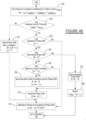
Figure 4Ai-4As is a detailed flowchart illustrating operations performed by the apparatus ofFigure 1 in detecting a residual current condition, as well as a specific voltage phase; and -
Figure 4B shows additional operations that may be performed by the apparatus ofFigure 1 if the apparatus includes dedicated current metering circuitry to support measurement of current at individual AC outlets. - The following description is merely exemplary in nature and is not intended to limit the present disclosure, application, or uses. It should be understood that throughout the drawings, corresponding reference numerals indicate like or corresponding parts and features.
- Referring to
Figure 1 , one embodiment of an apparatus 10 is shown which forms an intelligent equipment rack power distribution unit able to monitor for residual current associated with any one or more of a plurality of rack mounted assets being powered by the apparatus 10. For convenience, the apparatus 10 will be referred to throughout simply as "PDU 10". - The PDU 10 may incorporate a residual current monitor
current transformer 11, hereinafter simply "RCMCT 11", which is operatively coupled to three-phase AC power from some upstream device (e.g., AC mains source, UPS, etc.) and which senses a residual current condition affecting any one or more of a plurality ofAC outlets 10a of the PDU. The operation of theRCMCT 11 and its connections to other components of the PDU 10 will be described in greater detail in the following paragraphs. - The PDU 10 in this example may also incorporate a communications module RPC2 12 (hereinafter simply "
RPC 12"), which may be a hot-swappable web card which is installed in the PDU 10, and in this example may be the RPC2™ Network Interface Card available from Vertiv Co., assignee of the present disclosure. TheRPC 12 may include amicrocontroller 14 and preferably also a non-volatile (NV)memory 16. TheRPC 12 may also include a plurality of ports including, but not limited to, aLAN Ethernet port 18, an Expansion/Management port 20, a port 22 for coupling to a display module (e.g., "BDM" or "Basic Display Module" available from the assignee of the present disclosure), one or more 1-wire sensor ports 24, an RS-232port 26 and a USB port 28. - The PDU 10 further may include a Rack PDU Controller (RPDUC) 30 having a
microcontroller 32 and anon-volatile memory 34, and one or more branch receptacle controllers (BRC) 36. The RPDUC 30 receives current information from the RCMCT 11. EachBRC 36 may have a complex programmable logic device (CPLD) 38 having a voltage andcurrent sensing subsystem 38a which senses of a loss of AC input power, a plurality ofbistable relays 40, and an open circuit breaker (OCB)detection subsystem 42 which senses for an open circuit breaker condition. The RPDUC 30 is in bidirectional communication with each of the BRCs 36 via a bus 44. The RPC 12 is in bidirectional communication with the RPDUC 30 via a bus 46. A reset switch 48, which is easily accessible by a user via a faceplate of the PDU 10, is provided for enabling the user to initiate a hard reset of the PDU. -
Figure 1 also shows a plurality of branch circuit breakers (CB) 50 that each receives AC input power directly from the current-carrying conductors passing through theRCMCT 11. By "branch" circuit breaker it is meant that each one of the CBs 50 is typically associated with onespecific BRC 36. TheOCB detection subsystem 42 monitors the CBs 50 to detect when any one or more have been tripped to an open condition. And as explained above, eachBRC 36 includes a plurality ofbistable relays 40, which in one specific embodiment comprise eight (8) bistable relays. However, it will be appreciated that a greater or lesser number ofbistable relays 40 could be provided per branch. Mechanical bistable relays have coils and mechanical contacts. They can be single coil or dual coil relays. Also, more than one CB 50 may exist for eachBRC 36. For example, eachBRC 36 can have its bistable relays arranged in two sub banks, with a separate CB 50 associated with each sub-bank. As used herein, each sub-bank of aBRC 36 is a branch of the BRC. -
Figure 1 also shows the plurality ofAC power outlets 10a. In this example, each outlet is single-phase in line-neutral or line-line configuration, with its associated phase established at manufacturing time and saved inNV memory 16. Each outlet has a first associated optical element 10a1 and a second optical element 10a2. Optical elements 10a1 may each be an LED having a first color, for example green, that indicates a status of the specificbistable relay 40 associated with itsspecific AC outlet 10a. The second group of optical elements 10a2 may also be, for example, LEDs having a different color, for example red, for providing additional information to the user. Each one of the green LEDs 10a1 may indicate, for example, that thebistable relay 40 associated with thatspecific AC outlet 10a is closed, and an extinguished green LED 10a1 would therefore indicate that the associated bistable relay is open. EachAC power outlet 10a may be used to power an associated rack mounted asset (e.g., server, network switch, etc.) - The
RPDUC 30 is shown in greater detail inFigure 2 . Themicrocontroller 32 of theRPDUC 30 may include a staticrandom access memory 32a (hereinafter simply "SRAM 32a") and a non-volatile read only memory or non-volatilerandom access memory 32b (hereinafter simply "NV memory 32b"). TheSRAM 32a may contain a plurality of circular buffers 32a1 to hold current waveform data samples, while theNV memory 32b may be used to store gain coefficients 32b1 and ADC skew coefficients 32b2. The use of the circular buffers 32a1, the gain coefficients 32b1 and the ADC coefficients 32b2 will be discussed further in the following paragraphs. And while theSRAM 32a andNV memory 32b in this example are shown as part of themicrocontroller 32, it will be appreciated that they could be implemented as independent memory devices just as well. - The
RPDUC 30 includes a voltage sensing subsystem 52 and a current sensing subsystem 54. The subsystems 52 and 54 perform real time RMS voltage measurements and RMS current measurements, respectively, and thus monitor the power input from the AC power source. TheRCMCT 11 is also in communication with the current sensing subsystem 54. Three phase LEDs 55a-55c may be incorporated and/or operatively coupled to theRPDUC 30 that indicate the voltage and current conditions of each phase of the AC input, including the residual current condition. The monitored power information may be shared with theRPC 12 via bus 44. As noted above, the voltage andcurrent sensing subsystem 38a of eachBRC 36 also monitors for a loss of AC input power, so in this regard there is redundancy of this feature in theRPDUC 30 and theBRCs 36. The current sensing subsystem 54 of theRPDUC 30 receives an input current signal from each of the branch BRCs (collectively labeled for simplicity inFigure 2 with number 36) which it uses to perform its current sensing function. Eachbranch BRC 36 also includes a plurality of current transformers (CTs) 56 for independently measuring a current being drawn by theAC outlets 10a associated with each branch of bistable relays 40. The signals from each branch CT 56 are input to the current sensing subsystem 54 for analysis. - The
RPC 12 shown inFigure 1 manages, monitors and reports information about PDU 10 energy metering and power distribution status obtained from theRPDUC 30 to networked software clients. TheRPDUC 30 provides support for the energy metering measurements and calculations, control management, and communications interfaces to theRPC 12, as described above. TheRPDUC 30 communicates with eachBRC 36 and, except upon power loss, controls thebistable relays 40 of each BRC by sending command messages to each BRC to independently control each one of its associated bistable relays 40. - The
BRC 36, and more particularly itsCPLD 38, directly controls its bistable relays 40. TheBRC 36 also manages individual LED outlet operational status, and detects loss of an AC input power signal via line frequency monitoring performed by the voltage sensing portion of the voltage andcurrent sensing subsystem 38a, as well as using theOCB subsystem 42 to detect for an open circuit breaker condition. The bistable relays 40 of eachBRC 36 in this example require a nominal 16 msec pulse to their coils to change states, that is, to open or close their contacts. A reference herein to a bistable relay being "open" means that its contacts are open and power is off or interrupted at theoutlet 10a to which the bistable relay switches power. As used herein, "power up", "power down", "power failure", and "power cycle" refer to specific conditions of input AC line voltage, which is the AC power provided to theoutlets 10a through thebistable relays 40 of eachBRC 36. The term "Configured state", when used in connection with thebistable relays 40, means the state that a given bistable relay is configured to be in (i.e., open or closed) when power is on. For the purpose of the present disclosure, it may be understood that the term "configured state" means that thebistable relays 40 will, after the PDU 10 is powered up, have closed contacts in order to switch power on at theAC outlets 10a." - The
RPC 12 commands theRPDUC 30 via a SMBus (I2C) communication bus, bus 46 inFigure 1 in this example, which in turn, commands theBRC 36 via a SPI communication bus, which is bus 44 in this example, to configure the relay state of eachbistable relay 40. TheRPDUC 30 is capable of autonomous behavior withoutRPC 12 commands. The one ormore BRCs 36 are each capable of autonomous behavior withoutRPDUC 30 commands. - The PDU 10 and its method of operation significantly extend the ability of traditional systems and methods for measuring residual current by incorporating statistical analysis. The statistical analysis is used to infer which voltage phase of the AC input voltage is affected by the path of a residual current. If the PDU 10 is equipped with dedicated current metering circuitry for each
outlet 10a (Figure 1 ), the statistical analysis can also be used to infer which one of theAC outlets 10a of the PDU 10 is affected by the path of a residual current. In this manner it is possible to quickly detect which one of a plurality of rack assets connected to theAC outlets 10a of the PDU 10 is the faulty device giving rise to the residual current flow so that the faulty device can be quickly disconnected from the PDU. This enables the remaining, properly functioning, devices operating on the PDU 10 to continue in their operation without the need to independently power down each of the properly functioning devices coupled to the PDU in order to identify the offending device. - Referring to
Figure 3 , a flowchart 300 is shown providing a high-level summary of the operations that may be performed by the PDU 10 in carrying out the detection of a residual current associated with any voltage phase of the AC input voltage and with anyAC outlet 10a of the PDU 10.Figure 3 also provides a list of the discrete operations that may be performed to carry out each of the high-level operations, to be discussed below with reference toFigure 4 . It should be noted that operations illustrated in the flowchart 300 may be performed by themicrocontroller 32 of theRPDUC 30 of the PDU 10, but for convenience it will be stated hereinafter that an operation may be performed by the PDU 10 or by themicrocontroller 32. - As an overview of the various operations shown in
Figure 3 , it will be understood that the PDU 10 detects the voltage phase in which the residual current path is flowing. If the PDU 10 supports individual current measurements at the outlets, then the PDU 10 also detects theAC outlet 10a through which the residual current path is flowing. The PDU 10 accomplishes this by using statistical time series analysis along with a Pearson's correlation coefficient calculation to measure the linear dependence between the discretely sampled residual current waveform for each phase and the aggregation of the AC outlets' 10a discretely sampled current waveforms calculated per phase, in turn. The per-phase aggregation may result from current measurements by a single sensor dedicated to a set of same-phased outlets or by a plurality of sensors per each outlet. The Pearson's correlation coefficient is the covariance of the compared values divided by the product of their standard deviations. A residual current as low as 1mA can be accurately measured/detected along with its associated voltage phase source. From this information it can be reliably determined whichAC outlet 10a the residual current is flowing out of. The presence of a residual current is constantly measured and monitored for in real-time. When a residual current threshold level is exceeded, an audible alarm may be sounded, an event notification may be delivered, and a visual indicator of the associated phase may be flashed on the phase LED 55a-55c and/or on the LED corresponding to an outlet of the intelligent power strip, if the PDU 10 is equipped with dedicated current metering circuitry per outlet, until the residual current path is eliminated or the alarm threshold is increased. - Referring further to
Figure 3 , the methodology employed by the PDU 10 may begin atoperation 302, with analog-to-digital conversion (ADC) and time series collection of residual and outlet current waveform samples. This is accomplished by means ofdiscrete operation 106, to be discussed below. Atoperation 304, the root mean square (RMS) value of the residual current may be calculated, by means ofdiscrete operations operation 306, the currents of individual outlets and aggregated outlet (phase) currents may be calculated. This may be accomplished by means ofdiscrete operations discrete operations operation 310, Pearson's correlation coefficient may be calculated of the variables relating to RC and individual outlet currents by means ofdiscrete operations operation 310 supports both in-phase and quadrature phase shift and incremental phase shift up to 15 degrees. Atoperation 312, the phase having the maximum positive Pearson's correlation is calculated when the RC RMS exceeds the RC RMS threshold; this is accomplished bydiscrete operation 158. If the PDU 10 is equipped with dedicated current metering circuitry for eachoutlet 10a,operation 314 may be performed to determine the outlet having the maximum positive Pearson's correlation when the RC RMS exceeds the RC RMS threshold. This is accomplished by the sequence ofdiscrete operations - Referring to
Figure 4Ai-4As , aflowchart 100 is shown illustrating various discrete operations that may be performed by the PDU 10 in carrying out the detection of a residual current associated with any voltage phase of the AC input voltage and with any voltage phase related to theAC outlets 10a of the PDU 10. It should be noted that operations illustrated in theflowchart 100 may be performed by themicrocontroller 32 of theRPDUC 30 of the PDU 10, but for convenience it will be stated hereinafter that an operation may be performed by the PDU 10 or by themicrocontroller 32. - Referring further to
Figure 4Ai-4As , the methodology employed by the PDU 10 may begin atoperation 102 where phase analysis variables a (quadrature phase) and cp (incremental phase) are initialized to zero, and atoperation 104 the ADC skews K1 and K, may be pre-calculated. The quadrature phase may alternately be assigned 0° and 90° in later operations. The incremental phase ϕ has a unit magnitude dependent upon the number of equispaced ADC samples captured per line cycle (e.g., if 64 samples are captured per line cycle, then a unit of incremental phase equals 360°/64 or approximately 5.6 degrees). The ADC skews Kr (for the residual current ADC channel) and Ko (for each outlet current channel) are pre-calculated time delays, representing the delta time between successive samples captured one after another; if each sample duration is approximately n microseconds, with m outlet currents the last sample is captured after (m-1)*n µsec. The skew adjustment uses a linear extrapolation to estimate an extrapolated normalized current waveform sample, as if all m outlet currents were sampled simultaneously bymicrocontroller 32. At operation 106 a time series of sampled current waveforms received over an AC power line cycle may be collected. - At
operation 108 the starting index n of the sr circular buffer 32a1 for RCM current waveform samples is initialized in accordance withEquation 1 below.

- At operation 110 a test may then be conducted on the sr buffer index (n < N) to determine when the time series has been completely processed. If the test produces a "Yes" answer, then at
operation 112 the residual current sample is filtered by its exponentially weighted moving average and copied into buffer i, in accordance withEquation 2 below. The value of β1 (in this example, 0.05) is dependent upon sample rate (in this example, the controller samples 64 times per line cycle) and provides acceptable smoothing characteristics for 1 ma precision while remaining responsive to changing conditions.

- At
operation 114, corrections to remove electronic and signal offsets and apply calibrated scalars determined at manufacturing time are then calculated for Ir, ADC skew, mean and gain, as indicated byEquation 3 below.

- At
operation 116, the residual current sample minimum/maximum peaks may be determined, as indicated by Equation 4 below. These may be saved in order to later determine the half-wave symmetry of the current waveform (i.e., full-wave or half-wave characteristic).

- At
operation 118, themicrocontroller 32 may then calculate the residual current sample integral in accordance with Equation 5 below. Because a zero-valued integral is expected over a line cycle of a half-wave symmetrical periodic waveform,operation 118 enables precise correction of creeping offset errors due to small measurement imprecision.

- At
operation 120 the residual current sample may be corrected with an offset depending upon its detected full-wave or half-wave characteristic, in accordance with Equation 6 below. If full-wave, no gross offset adjustment occurs atoperation 120. If half-wave, then a gross offset adjustment is made to reposition the flat baseline of the residual current waveform at the mathematical zero offset positon so that a true RMS calculation can be made.

- At
operation 122, themicrocontroller 32 may initialize the starting index (m = 0) of io buffers for outlet current waveform samples, where M is the number of current sensors related toAC outlets 10a. If the PDU 10 supports individual outlet monitoring, then M = number of AC outlets (i.e., number ofAC outlets 10a inFigure 1 ). If the PDU 10 does not support individual outlet monitoring, then only a single current sensor per set or bank of outlets is available, and M = number of banks of outlets per phase. - At
operation 124 themicrocontroller 32 may then test the io buffer index (m<M) to check if another AC outlet current sample needs to be processed. If this test produces a "Yes" answer, thenoperation 126 is performed, where the AC outlet current sample is filtered and copied into the buffer io in accordance with Equation 7 below.

- At
operation 128, themicrocontroller 32 may then correct for io[m] ADC skew, mean and gain in accordance with Equation 8 below.

- At
operation 130 themicrocontroller 32 may then calculate phase currents (IL1, IL2, and IL3 in this example) for each phase of the AC input (phases L1, L2, and L3 in this example) by aggregating each of the same-phased M outlet current waveform samples. This operation is performed in accordance withEquation 9 as shown below.

- At
operation 132, themicrocontroller 32 may then calculate the outlet current sample integral in accordance with Equation 10 below. Because a zero-valued integral is expected over a line cycle of a half-wave symmetrical, periodic waveform, this operation enables precise correction of creeping offset errors due to small measurement imprecision.

- At
operation 134 themicrocontroller 32 may then calculate the Pearson's terms for the outlet current sample using the corrected residual current values fromoperation 120. This operation is performed in accordance withEquation 11 below:

- At
operation 136 the outlet index is incremented ( m←m + 1), and operations from 124 may then be re-performed. - If the io buffer index test at
operation 124 produces a "No" answer, this means that all output current samples have been processed and themicrocontroller 32 may then executeoperation 180, in which the microcontroller calculates the Pearson's terms for the phase current samples, in accordance withEquation 12 below.

- At
operation 182 themicrocontroller 32 may then calculate the Pearson's term for the residual current sample (ΣIr 2). The sample index (n←n + 1) may then be incremented atoperation 184, andoperation 110 may be repeated, and operations from 110 may then be re-performed. - If the sr buffer index test at operation 110 (n<N) produces a "No" answer, then at
operation 138 the time series has been completely processed and themicrocontroller 32 may calculate the RMS residual current in accordance withEquation 13 below.

- The
microcontroller 32 may then calculate the running mean of residual and outlet current samples from weighted sample integrals calculated inoperations operation 140, in accordance withEquation 14 below.

- The
microcontroller 32 may then initialize the half/full wave offset (irΔ = 0) as indicated atoperation 142, and then perform a test of the positive half-wave residual current atoperation 144 by magnitude comparison of half-wave symmetry, in accordance withEquation 15 below.

- If the test at
operation 144 produces a "Yes" answer, then atoperation 146 themicrocontroller 32 calculates the positive offset in accordance withEquation 16 below.

- If the test at
operation 144 produces a "No" answer or ifoperation 146 has been performed, then atoperation 148 themicrocontroller 32 tests the negative half-wave residual current in accordance with Equation 17.

- If the test at
operation 148 produces a "Yes" answer, then atoperation 150 themicrocontroller 32 calculates the negative offset in accordance withEquation 18 below.

- If either
operation 148 produces a "No" answer or ifoperation 150 has been performed, then atoperation 152 themicrocontroller 32 calculates the Pearson's correlation coefficient for the variables related to the residual and in-phase phase currents in accordance with Equation 19 below.

- At
operation 154 themicrocontroller 32 calculates the Pearson's correlation coefficients for the variables related to the residual and the in-phase and quadrature phase outlet currents in accordance with Equation 20 below.

- At
operation 156 themicrocontroller 32 calculates the RMS Pearson's correlation coefficient from results of Equation 20, in accordance with Equation 21 below.

- At
operation 158 themicrocontroller 32 then sorts the Pearson's correlation coefficients for the phase currents (e.g.,
- If the PDU 10 does not support measurement of current at individual AC outlets, then at
operation 178A, themicrocontroller 32 reports the residual currentRMS (IrRMS) and the phase with maximum Pearson's correlation coefficient ().
Operations - With reference to
Figure 4B , it will be understood that the sequence of operations from 160 through 178B is performed only if the PDU 10 includes dedicated current metering circuitry to support measurement of current at individual AC outlets. If this is the case, then inFigure 4B atoperation 160, themicrocontroller 32 then sorts the Pearson's correlation coefficients for the outlet currents (e.g., rov = roRMS(1) > roRMS(2)... > roRMS(m)) in order to determine the maximum positive Pearson's correlation coefficient value (romax). - At
operation 162 themicrocontroller 32 then performs a test of the residual current threshold (IrRMS > Irthres). If this test produces a "Yes" answer, indicating the residual current threshold has been exceeded, then atoperation 163 the value of the quadrature phase variable α is tested (α = 1) for the presence of a quarter cycle or quadrature phase shift. If this test produces a "Yes" answer, then at then atoperation 164 themicrocontroller 32 tests the maximum incremental phase shift angle (ϕ = 15°) to determine if the incremental phase shift angle has reached 15°. This is done in order to evaluate the maximum Pearson's correlation coefficient over a small range, in case a resistive fault has a small parallel stray capacitance which would produce a corresponding incremental phase shift of the residual current waveform with respect to the outlet current waveform. A small power factor difference between outlet loads would result in a larger, more discriminating maximum correlation and therefore even more reliable outlet detection. If this test produces a "No" answer, then atoperation 166 themicrocontroller 32 tests to determine if the maximum outlet correlation (rov > rov') has been exceeded. If the test atoperation 166 produces a "Yes" answer, then atoperation 168 themicrocontroller 32 saves the new maximum outlet correlation and its phase shift (ϕ'←ϕ and rov'←rov). Afteroperation 168, or if the test atoperation 166 produces a "No" answer, then atoperation 170 themicrocontroller 32 increments the phase shift (ϕ←ϕ + 1). - If the residual current threshold test at
operation 162 produces a "No" answer, then atoperation 172 themicrocontroller 32 resets the phase shift maximum correlation (ϕ = 0, ϕ' = 0, and
operations operation 163 produces a "No" answer, then atoperation 174 themicrocontroller 32 may calculate alternate in-phase and quadrature phase shifts (α←(α + 1) mod 1). The outlet current waveforms may have non-linear sinusoidal characteristics and/or be phase shifted for reactive loads, producing a non-unity power factor. Thus, considering the in-phase and quadrature calculations in testing for maximum Pearson's correlation coefficient, a larger discriminating result is achieved. Afteroperation 174 is performed, thenoperations - If the test for maximum incremental phase shift angle at
operation 164 produces a "Yes" answer, then atoperation 176 themicrocontroller 32 sets the incremental phase shift (ϕ ← ϕ'), and then at operation 178B reports the residual current RMS (IrRMS), the outlet with maximum Pearson's correlation coefficient (rov), and the phase with maximum Pearson's correlation coefficient (rLv).Operations - The PDU 10 and its method of operation as described herein do not require costly circuitry dedicated per each phase and/or outlet to directly measure residual current flow. A particularly important and useful property of the PDU 10 and its method of operation is that it is invariant to scale or magnitude of the compared values. A set of correlation values are calculated between -1 and +1, where a value closest to +1 means the linear dependence and phase matching is the highest, and therefore, the most likely path of the residual current flow. A residual current as low as 1mA can be accurately measured and its associated voltage phase source and flow through outlet can be reliably determined.
- The various embodiments of the present disclosure provide a significant advantage over prior art methods that can merely measure for a residual current condition. The Vertiv MPH2 rack PDU controller firmware, for example, may be used to support the methodology described herein.
- The various embodiments and methodology of the present disclosure presents a lower cost solution when compared to directly measuring differential currents at each phase and/or outlet. The various embodiments and methodology of the present disclosure offer highly sensitive detection of small phase differences of 0.5% power factor between compared current waveforms. The methodology of the present disclosure automatically discriminates the most likely residual current path external to the unit, so the powered device causing the fault can be quickly removed to minimize down times and reduce the associated costs, rather than being required to manually identify the residual current path by a trial and error method.
- The various embodiments of the PDU 10 and its method of operation further facilitate a preventative maintenance program through the ability to obtain additional indirect information about the health of insulation system(s) associated with electrical cabling being used, and thus may help prevent unanticipated downtime of all types of electrically powered devices. The PDU 10 and its method of operation, by its ability to quickly detect residual currents and identify specific AC outlets that such currents are associated with, may also provide a measure of fire protection for a facility in which the present disclosure is used.
- While various embodiments have been described, those skilled in the art will recognize modifications or variations which might be made without departing from the present disclosure. The examples illustrate the various embodiments and are not intended to limit the present disclosure. Therefore, the description and claims should be interpreted liberally with only such limitation as is necessary in view of the pertinent prior art.
Claims (13)
- A method for detecting a residual current flowing through an intelligent power strip (IPS) having at least one alternating current (AC) power outlet (10a), the method comprising:obtaining current sensing information;performing an analog-to-digital conversion (ADC) of the current sensing information to obtain ADC samples;obtaining a time series collection of the ADC samples as residual and outlet current waveform samples;using a microcontroller (32) to perform operations including:calculating a residual current (RC) RMS value for the obtained residual current waveform samples;calculating phase current from the aggregation of the outlet current waveform samples having the same phase;calculating Pearson's correlation coefficients for variables relating to the residual current waveform samples and to the phase current;calculating Pearson's correlation coefficients for the variables relating to residual current waveform samples and individual outlet current waveform samples from each AC power outlet;determining the phase having a maximum positive Pearson's correlation when the residual current RMS value is greater than a predetermined residual current RMS threshold; anddetermining an individual one of the AC power outlets having the maximum positive Pearson's correlation when the residual current RMS value is greater than the predetermined RMS threshold.
- The method of claim 1, wherein calculating residual current (RC) RMS value includes filtering and copying residual current samples into a circular memory buffer (sr).
- The method of claim 2, wherein calculating said residual current (RC) RMS value further comprises filtering by an exponentially weighted moving average of the residual current samples in accordance with an Equation:


- The method of claim 1, wherein calculating residual current (RC) RMS includes determining corrections for analog-to-digital conversion (ADC) skews for a residual current ADC channel (ADC Kr) and an outlet current channel (ADC Ko), wherein the ADC Kr and ADC Ko skews are pre-calculated time delays representing a delta time between successive samples captured one after another for each one of a residual current ADC channel and an ADC outlet current channel.
- The method of claim 1, wherein calculating phase current waveforms from the aggregation of the load current waveform samples having the same phase includes calculating an outlet current sample.
- The method of claim 1, wherein calculating residual current (RC) RMS includes calculating a residual current sample integral to remove errors due to measurement imprecision.
- The method of claim 6, further comprising correcting each of the obtained residual current samples with an offset.
- The method of claim 1, wherein calculating the Pearson's correlation coefficient for residual currents and phase currents for each outlet includes calculating the Pearson's correlation coefficients for variables related to the residual and the in-phase and quadrature phase load current samples.
- The method of claim 8, further comprising using the microcontroller to sort the Pearson's correlation coefficients for both of the phase and individual load current samples in order to determine the maximum positive Pearson's correlation.
- The method of claim 1, wherein calculating residual current (RC) RMS includes:1) testing a positive half-wave residual current by magnitude comparison of half-wave symmetry, and when the test produces a positive answer, then calculating a positive offset; and2) testing a negative half-wave residual current by magnitude comparison of half-wave symmetry and, when this test produces a positive answer, then calculating a negative offset.
- A system for detecting a residual current flowing through an intelligent power strip (IPS) having at least one alternating current (AC) power outlet (10a), the system comprising:a microcontroller (34);a circular buffer (sr) for storing measured residual current samples measured by the controller;an outlet current buffer (io) for storing outlet current samples measured by the controller;a current sensing subsystem (38a) for obtaining current sensing information;the microcontroller being configured to:use the current sensing subsystem to perform an analog-to-digital (ADC) conversion of the current sensing information to obtain ADC samples;manage a time series collection of the ADC samples as residual and outlet current waveform samples, and saving the residual current waveform samples in the circular buffer, and saving the outlet current waveform samples in the outlet current buffer;calculate a residual current (RC) RMS value for the obtained residual current samples;calculate phase current from the aggregation of the outlet current waveform samples having the same phase;calculate Pearson's correlation coefficients for variables relating to residual current and the phase current;calculate Pearson's correlation coefficients for the variables relating to residual current and each individual outlet current waveform from each AC power outlet;determine the phase having a maximum positive Pearson's correlation when the residual current RMS value is greater than a predetermined residual current RMS threshold; anddetermine an individual one of the AC power outlets having the maximum positive Pearson's correlation when the residual current RMS value is greater than the predetermined RC RMS threshold.
- The system of claim 11, wherein the microcontroller is further configured to calculate the Pearson's correlation coefficients for variables related to the residual current samples, the in-phase and quadrature phase portions of the outlet current waveform samples.
- The system of claim 11, wherein in calculating each one of said residual current (RC) RMS values, the microcontroller is configured to filter, by an exponentially weighted moving average, the residual current (RC) RMS value.
Applications Claiming Priority (2)
| Application Number | Priority Date | Filing Date | Title |
|---|---|---|---|
| US201762443308P | 2017-01-06 | 2017-01-06 | |
| PCT/US2018/012615 WO2018129340A1 (en) | 2017-01-06 | 2018-01-05 | System and method of identifying path of residual current flow through an intelligent power strip |
Publications (2)
| Publication Number | Publication Date |
|---|---|
| EP3566065A1 EP3566065A1 (en) | 2019-11-13 |
| EP3566065B1 true EP3566065B1 (en) | 2023-03-22 |
Family
ID=61074549
Family Applications (1)
| Application Number | Title | Priority Date | Filing Date |
|---|---|---|---|
| EP18701967.4A Active EP3566065B1 (en) | 2017-01-06 | 2018-01-05 | System and method of identifying path of residual current flow through an intelligent power strip |
Country Status (4)
| Country | Link |
|---|---|
| US (3) | US20180196098A1 (en) |
| EP (1) | EP3566065B1 (en) |
| CN (1) | CN110168391B (en) |
| WO (1) | WO2018129340A1 (en) |
Families Citing this family (15)
| Publication number | Priority date | Publication date | Assignee | Title |
|---|---|---|---|---|
| US10288680B2 (en) * | 2017-10-12 | 2019-05-14 | General Electric Company | Method and system for monitoring quality and controlling an alternating current power supply provided to an ultrasound system from a power outlet |
| US10566746B1 (en) * | 2019-01-29 | 2020-02-18 | George Breeden | Illuminated electricity distribution device |
| CN110632457A (en) * | 2019-09-25 | 2019-12-31 | 广西电网有限责任公司河池供电局 | Power distribution network fault positioning method based on transient traveling wave time sequence correlation coefficient |
| CN110780250B (en) * | 2019-09-30 | 2021-11-09 | 国创移动能源创新中心(江苏)有限公司 | Automatic calibration system and method for residual current detection |
| US11906575B2 (en) * | 2020-04-21 | 2024-02-20 | International Business Machines Corporation | Electrical power analyzer for large and small scale devices for environmental and ecological optimization |
| CN113721070B (en) * | 2020-05-26 | 2024-03-29 | 天津首瑞智能电气有限公司 | Residual current detection device and residual current detection method |
| TWI741716B (en) * | 2020-08-03 | 2021-10-01 | 擎宏電子企業有限公司 | A method for the user to easily check whether the programmable ac power distributor's input power and load are normal when it is turned on by the light signal |
| CN111965533B (en) * | 2020-08-18 | 2023-04-07 | 浙江天正电气股份有限公司 | Residual current calculation method, calculation device, storage medium and detection equipment |
| EP3975363A1 (en) * | 2020-09-28 | 2022-03-30 | ABB Schweiz AG | Method and system for detecting phenomenon in electrical power network |
| CN112072609B (en) * | 2020-09-28 | 2022-06-24 | 国网山东省电力公司莱芜供电公司 | Method for adjusting action current of leakage protector |
| CN113030559B (en) * | 2021-05-21 | 2021-08-24 | 杭州并坚科技有限公司 | Method for detecting residual current of detector |
| US20230393638A1 (en) * | 2022-06-06 | 2023-12-07 | Server Technology, Inc. | Per outlet residual current monitoring for power distribution units |
| US20240118326A1 (en) * | 2022-10-04 | 2024-04-11 | Vertiv Corporation | System and method of virtualized energy metering for intelligent power distribution equipment |
| CN115616437B (en) * | 2022-11-18 | 2023-03-14 | 西安弘捷电子技术有限公司 | Intelligent debugging control method and system for EPC special power supply |
| CN116908518B (en) * | 2023-07-13 | 2024-04-05 | 浙江恒业电子股份有限公司 | Acquisition terminal with residual current detection function |
Family Cites Families (45)
| Publication number | Priority date | Publication date | Assignee | Title |
|---|---|---|---|---|
| US4626698A (en) | 1984-12-21 | 1986-12-02 | General Electric Company | Zero crossing synchronous AC switching circuits employing piezoceramic bender-type switching devices |
| US5267120A (en) | 1987-05-04 | 1993-11-30 | Digital Appliance Controls, Inc. | Relay control apparatus |
| US4864157A (en) | 1988-05-12 | 1989-09-05 | Spatron Corporation | Reduced arcing contact switching circuit |
| US5361184A (en) | 1992-10-20 | 1994-11-01 | Board Of Regents Of The University Of Washington | Adaptive sequential controller |
| US5363669A (en) | 1992-11-18 | 1994-11-15 | Whirlpool Corporation | Defrost cycle controller |
| US5640113A (en) | 1994-05-06 | 1997-06-17 | The Watt Stopper | Zero crossing circuit for a relay |
| US5838077A (en) | 1995-07-12 | 1998-11-17 | Pittway Corporation | Control system for switching loads on zero crossing |
| US5821642A (en) | 1996-11-04 | 1998-10-13 | Hubbell Incorporated | Arc prevention circuit for a mechanical switch |
| WO1999000811A1 (en) | 1997-06-25 | 1999-01-07 | Nkt Research Center A/S | A method of connecting and disconnecting an ac voltage to/from a load, as well as a switch comprising a relay |
| US6233132B1 (en) | 1998-09-03 | 2001-05-15 | Ranco Incorporated Of Delaware | Zero cross relay actuation method and system implementing same |
| US6232675B1 (en) | 1998-11-14 | 2001-05-15 | Hewlett-Packard Company | Power distribution apparatus comprising relay devices for controlling current flow along power paths of the power distribution apparatus |
| US6768615B2 (en) | 2002-06-24 | 2004-07-27 | Daniel Liu | Spark elimination circuit for controlling relay contacts |
| US6903554B2 (en) | 2003-07-15 | 2005-06-07 | Carrier Corporation | Control of relay opening events |
| US8154841B2 (en) | 2003-09-03 | 2012-04-10 | Legrand Home Systems, Inc. | Current zero cross switching relay module using a voltage monitor |
| DE102005028881B4 (en) * | 2005-06-22 | 2010-04-29 | Siemens Ag | Fault current analyzer for detecting a fault current and device with fault current detection function |
| US7227732B2 (en) | 2005-06-23 | 2007-06-05 | Chu-Li Wang | Apparatus and method for controlling open/close timing of relay |
| JP2007215367A (en) | 2006-02-13 | 2007-08-23 | Meidensha Corp | Remote control type electric outlet |
| US7619868B2 (en) | 2006-06-16 | 2009-11-17 | American Power Conversion Corporation | Apparatus and method for scalable power distribution |
| US7502697B2 (en) * | 2006-09-28 | 2009-03-10 | Programmable Division Of Xantrex Technology, Inc. | AC output power supply with digital feedback loop |
| CA2683429C (en) | 2007-04-05 | 2017-03-07 | Georgia Tech Research Corporation | Voltage surge and overvoltage protection |
| GB2455491A (en) * | 2007-10-02 | 2009-06-17 | Deepstream Technologies Ltd | Real current circuit protection device |
| JP2009134564A (en) | 2007-11-30 | 2009-06-18 | Daikin Ind Ltd | Operation control device of electric equipment |
| US8773827B2 (en) | 2008-02-19 | 2014-07-08 | Simply Automated Incorporated | Intelligent circuit breaker apparatus and methods |
| US7795759B2 (en) | 2008-06-27 | 2010-09-14 | iGo, Inc | Load condition controlled power strip |
| EP2404354B1 (en) | 2009-03-04 | 2018-11-07 | Server Technology, Inc. | Monitoring power-related parameters in a power distribution unit |
| JP2010252425A (en) | 2009-04-10 | 2010-11-04 | Chugoku Electric Power Co Inc:The | Apparatus power control apparatus |
| AU2010265883B2 (en) | 2009-06-25 | 2016-02-11 | Server Technology, Inc. | Power distribution apparatus with input and output power sensing and method of use |
| US8614866B2 (en) | 2009-09-14 | 2013-12-24 | Electronic Systems Protection, Inc. | Hybrid switch circuit |
| US8332670B2 (en) * | 2009-09-23 | 2012-12-11 | Hitachi, Ltd. | Method and apparatus for discovery and detection of relationship between device and power distribution outlet |
| US8248109B2 (en) | 2010-01-11 | 2012-08-21 | Asco Power Technologies, L.P. | Methods and systems for detection of zero crossings in a signal |
| US8675325B2 (en) | 2010-10-20 | 2014-03-18 | Schneider Electric USA, Inc. | Electronic circuit breaker with alternate mode of operation using auxiliary power source |
| US9166396B2 (en) | 2011-01-31 | 2015-10-20 | Electronic Systems Protection, Inc. | Power conditioning, distribution and management |
| US8639459B1 (en) | 2011-03-30 | 2014-01-28 | Amazon Technologies, Inc. | System and method for monitoring power distribution units |
| US8559154B2 (en) | 2011-09-01 | 2013-10-15 | Osram Sylvania Inc. | Systems and methods for switching a relay at zero cross |
| CN202512697U (en) * | 2011-12-23 | 2012-10-31 | 天水长城电气科技开发有限公司 | Residual current type electrical fire monitoring detector |
| US8694291B2 (en) * | 2012-01-19 | 2014-04-08 | Verdigris Technologies, Inc. | System and method of waveform analysis to identify and characterize power-consuming devices on electrical circuits |
| US20130286528A1 (en) | 2012-04-27 | 2013-10-31 | Hendon Semiconductors Pty Ltd | Electrical relay control arrangement for switching an electrical relay at zero crossing of an ac mains supply |
| FR2993670B1 (en) * | 2012-07-20 | 2014-07-11 | Schneider Electric Ind Sas | DIRECTIONAL DETECTION OF SENSITIVE LAND DEFECT MEDIUM VOLTAGE BY LINEAR CORRELATION |
| US8737030B2 (en) | 2012-09-14 | 2014-05-27 | General Electric Company | Power distribution systems and methods of operating a power distribution system |
| US9122466B1 (en) | 2012-11-01 | 2015-09-01 | Amazon Technologies, Inc. | Power system reconfiguration with automatic transfer switch |
| US20140268474A1 (en) | 2013-03-13 | 2014-09-18 | Lutron Electronics Inc., Co. | Method of closing a relay switch and appartus thereof |
| US9425011B2 (en) | 2013-08-26 | 2016-08-23 | General Electric Company | Method and system for soft switching of a relay |
| US10877077B2 (en) | 2013-12-26 | 2020-12-29 | Schneider Electric It Corporation | Systems and methods for determining input current of a power distribution unit |
| US10250032B2 (en) | 2015-04-24 | 2019-04-02 | Vertiv Corporation | Intelligent power strip with management of bistable relays to reduce current in-rush |
| CN105891676B (en) * | 2016-04-12 | 2018-09-21 | 上海交通大学 | The flexible high pressure DC line protection method of current dependence |
-
2018
- 2018-01-05 WO PCT/US2018/012615 patent/WO2018129340A1/en unknown
- 2018-01-05 CN CN201880006093.5A patent/CN110168391B/en active Active
- 2018-01-05 US US15/863,102 patent/US20180196098A1/en not_active Abandoned
- 2018-01-05 US US15/863,519 patent/US10677823B2/en active Active
- 2018-01-05 EP EP18701967.4A patent/EP3566065B1/en active Active
-
2020
- 2020-05-07 US US16/869,205 patent/US10996248B2/en active Active
Also Published As
| Publication number | Publication date |
|---|---|
| CN110168391B (en) | 2021-11-16 |
| US20200400728A1 (en) | 2020-12-24 |
| US10677823B2 (en) | 2020-06-09 |
| WO2018129340A1 (en) | 2018-07-12 |
| US10996248B2 (en) | 2021-05-04 |
| CN110168391A (en) | 2019-08-23 |
| EP3566065A1 (en) | 2019-11-13 |
| US20180196091A1 (en) | 2018-07-12 |
| US20180196098A1 (en) | 2018-07-12 |
Similar Documents
| Publication | Publication Date | Title |
|---|---|---|
| EP3566065B1 (en) | System and method of identifying path of residual current flow through an intelligent power strip | |
| US10739414B2 (en) | Determining status of electric power transmission lines in an electric power transmission system | |
| AU2021203476B2 (en) | Nested microgrid control system | |
| US11211800B2 (en) | Method and system for locating the source of events in power distribution systems using distribution-level PMU data | |
| CN103503262B (en) | For monitoring the method and apparatus of current transformer in differential protective system | |
| CN104777397A (en) | Distribution line single-phase break line judgment and positioning method based on line voltage vector criterion | |
| CA2531416A1 (en) | System, apparatus and method for detection of electrical faults | |
| CA3036562C (en) | Method and system for hot socket detection in a utility meter | |
| AU2011200306A1 (en) | Power supply monitoring system | |
| CN114364994A (en) | Intelligent electronic device operation during power fluctuations | |
| KR102556772B1 (en) | Apparatus for detecting phase error of watt hour meter and method thereof | |
| US11921170B2 (en) | Protection of low-voltage distribution networks | |
| JP2003299215A (en) | Method for validity check of current transformer in switchgear, computer program and device, and switchgear provided with the device | |
| EP1134865B1 (en) | Detecting wire break in electrical network | |
| CN117424350B (en) | Ground connection pulse selection dynamic monitoring controller | |
| Estima et al. | Real-time Condition Monitoring of Grounding Transformers | |
| Udomparichatr | Overhead Line Broken Conductor Detection System Pilot Project | |
| CN211603523U (en) | Secondary voltage loop abnormity parallel detection device based on current injection method | |
| CN112255576A (en) | AC circuit abnormity identification method based on multi-source data | |
| Marques et al. | E-redes adopt new monometallic technology and predictive algorithm to minimize and predict LV neutral loss failures detection | |
| Zubic et al. | CURRENT-ONLY FAULT PASSAGE INDICATOR FOR HIGH IMPEDANCE GROUNDED NETWORKS |
Legal Events
| Date | Code | Title | Description |
|---|---|---|---|
| STAA | Information on the status of an ep patent application or granted ep patent |
Free format text: STATUS: UNKNOWN |
|
| STAA | Information on the status of an ep patent application or granted ep patent |
Free format text: STATUS: THE INTERNATIONAL PUBLICATION HAS BEEN MADE |
|
| PUAI | Public reference made under article 153(3) epc to a published international application that has entered the european phase |
Free format text: ORIGINAL CODE: 0009012 |
|
| STAA | Information on the status of an ep patent application or granted ep patent |
Free format text: STATUS: REQUEST FOR EXAMINATION WAS MADE |
|
| 17P | Request for examination filed |
Effective date: 20190613 |
|
| AK | Designated contracting states |
Kind code of ref document: A1 Designated state(s): AL AT BE BG CH CY CZ DE DK EE ES FI FR GB GR HR HU IE IS IT LI LT LU LV MC MK MT NL NO PL PT RO RS SE SI SK SM TR |
|
| AX | Request for extension of the european patent |
Extension state: BA ME |
|
| DAV | Request for validation of the european patent (deleted) | ||
| DAX | Request for extension of the european patent (deleted) | ||
| GRAP | Despatch of communication of intention to grant a patent |
Free format text: ORIGINAL CODE: EPIDOSNIGR1 |
|
| STAA | Information on the status of an ep patent application or granted ep patent |
Free format text: STATUS: GRANT OF PATENT IS INTENDED |
|
| RIC1 | Information provided on ipc code assigned before grant |
Ipc: H02H 3/32 20060101ALI20220928BHEP Ipc: G06F 1/26 20060101ALI20220928BHEP Ipc: G01R 31/52 20200101ALI20220928BHEP Ipc: G01R 31/42 20060101AFI20220928BHEP |
|
| INTG | Intention to grant announced |
Effective date: 20221017 |
|
| GRAS | Grant fee paid |
Free format text: ORIGINAL CODE: EPIDOSNIGR3 |
|
| GRAA | (expected) grant |
Free format text: ORIGINAL CODE: 0009210 |
|
| STAA | Information on the status of an ep patent application or granted ep patent |
Free format text: STATUS: THE PATENT HAS BEEN GRANTED |
|
| AK | Designated contracting states |
Kind code of ref document: B1 Designated state(s): AL AT BE BG CH CY CZ DE DK EE ES FI FR GB GR HR HU IE IS IT LI LT LU LV MC MK MT NL NO PL PT RO RS SE SI SK SM TR |
|
| REG | Reference to a national code |
Ref country code: GB Ref legal event code: FG4D |
|
| REG | Reference to a national code |
Ref country code: CH Ref legal event code: EP |
|
| REG | Reference to a national code |
Ref country code: DE Ref legal event code: R096 Ref document number: 602018047450 Country of ref document: DE |
|
| REG | Reference to a national code |
Ref country code: IE Ref legal event code: FG4D |
|
| REG | Reference to a national code |
Ref country code: AT Ref legal event code: REF Ref document number: 1555629 Country of ref document: AT Kind code of ref document: T Effective date: 20230415 |
|
| REG | Reference to a national code |
Ref country code: LT Ref legal event code: MG9D |
|
| P01 | Opt-out of the competence of the unified patent court (upc) registered |
Effective date: 20230621 |
|
| REG | Reference to a national code |
Ref country code: NL Ref legal event code: MP Effective date: 20230322 |
|
| PG25 | Lapsed in a contracting state [announced via postgrant information from national office to epo] |
Ref country code: RS Free format text: LAPSE BECAUSE OF FAILURE TO SUBMIT A TRANSLATION OF THE DESCRIPTION OR TO PAY THE FEE WITHIN THE PRESCRIBED TIME-LIMIT Effective date: 20230322 Ref country code: NO Free format text: LAPSE BECAUSE OF FAILURE TO SUBMIT A TRANSLATION OF THE DESCRIPTION OR TO PAY THE FEE WITHIN THE PRESCRIBED TIME-LIMIT Effective date: 20230622 Ref country code: LV Free format text: LAPSE BECAUSE OF FAILURE TO SUBMIT A TRANSLATION OF THE DESCRIPTION OR TO PAY THE FEE WITHIN THE PRESCRIBED TIME-LIMIT Effective date: 20230322 Ref country code: LT Free format text: LAPSE BECAUSE OF FAILURE TO SUBMIT A TRANSLATION OF THE DESCRIPTION OR TO PAY THE FEE WITHIN THE PRESCRIBED TIME-LIMIT Effective date: 20230322 Ref country code: HR Free format text: LAPSE BECAUSE OF FAILURE TO SUBMIT A TRANSLATION OF THE DESCRIPTION OR TO PAY THE FEE WITHIN THE PRESCRIBED TIME-LIMIT Effective date: 20230322 |
|
| PG25 | Lapsed in a contracting state [announced via postgrant information from national office to epo] |
Ref country code: SE Free format text: LAPSE BECAUSE OF FAILURE TO SUBMIT A TRANSLATION OF THE DESCRIPTION OR TO PAY THE FEE WITHIN THE PRESCRIBED TIME-LIMIT Effective date: 20230322 Ref country code: NL Free format text: LAPSE BECAUSE OF FAILURE TO SUBMIT A TRANSLATION OF THE DESCRIPTION OR TO PAY THE FEE WITHIN THE PRESCRIBED TIME-LIMIT Effective date: 20230322 Ref country code: GR Free format text: LAPSE BECAUSE OF FAILURE TO SUBMIT A TRANSLATION OF THE DESCRIPTION OR TO PAY THE FEE WITHIN THE PRESCRIBED TIME-LIMIT Effective date: 20230623 Ref country code: FI Free format text: LAPSE BECAUSE OF FAILURE TO SUBMIT A TRANSLATION OF THE DESCRIPTION OR TO PAY THE FEE WITHIN THE PRESCRIBED TIME-LIMIT Effective date: 20230322 |
|
| PG25 | Lapsed in a contracting state [announced via postgrant information from national office to epo] |
Ref country code: SM Free format text: LAPSE BECAUSE OF FAILURE TO SUBMIT A TRANSLATION OF THE DESCRIPTION OR TO PAY THE FEE WITHIN THE PRESCRIBED TIME-LIMIT Effective date: 20230322 Ref country code: RO Free format text: LAPSE BECAUSE OF FAILURE TO SUBMIT A TRANSLATION OF THE DESCRIPTION OR TO PAY THE FEE WITHIN THE PRESCRIBED TIME-LIMIT Effective date: 20230322 Ref country code: PT Free format text: LAPSE BECAUSE OF FAILURE TO SUBMIT A TRANSLATION OF THE DESCRIPTION OR TO PAY THE FEE WITHIN THE PRESCRIBED TIME-LIMIT Effective date: 20230724 Ref country code: ES Free format text: LAPSE BECAUSE OF FAILURE TO SUBMIT A TRANSLATION OF THE DESCRIPTION OR TO PAY THE FEE WITHIN THE PRESCRIBED TIME-LIMIT Effective date: 20230322 Ref country code: EE Free format text: LAPSE BECAUSE OF FAILURE TO SUBMIT A TRANSLATION OF THE DESCRIPTION OR TO PAY THE FEE WITHIN THE PRESCRIBED TIME-LIMIT Effective date: 20230322 |
|
| PG25 | Lapsed in a contracting state [announced via postgrant information from national office to epo] |
Ref country code: SK Free format text: LAPSE BECAUSE OF FAILURE TO SUBMIT A TRANSLATION OF THE DESCRIPTION OR TO PAY THE FEE WITHIN THE PRESCRIBED TIME-LIMIT Effective date: 20230322 Ref country code: PL Free format text: LAPSE BECAUSE OF FAILURE TO SUBMIT A TRANSLATION OF THE DESCRIPTION OR TO PAY THE FEE WITHIN THE PRESCRIBED TIME-LIMIT Effective date: 20230322 Ref country code: IS Free format text: LAPSE BECAUSE OF FAILURE TO SUBMIT A TRANSLATION OF THE DESCRIPTION OR TO PAY THE FEE WITHIN THE PRESCRIBED TIME-LIMIT Effective date: 20230722 |
|
| REG | Reference to a national code |
Ref country code: DE Ref legal event code: R097 Ref document number: 602018047450 Country of ref document: DE |
|
| PLBE | No opposition filed within time limit |
Free format text: ORIGINAL CODE: 0009261 |
|
| STAA | Information on the status of an ep patent application or granted ep patent |
Free format text: STATUS: NO OPPOSITION FILED WITHIN TIME LIMIT |
|
| PG25 | Lapsed in a contracting state [announced via postgrant information from national office to epo] |
Ref country code: SI Free format text: LAPSE BECAUSE OF FAILURE TO SUBMIT A TRANSLATION OF THE DESCRIPTION OR TO PAY THE FEE WITHIN THE PRESCRIBED TIME-LIMIT Effective date: 20230322 Ref country code: DK Free format text: LAPSE BECAUSE OF FAILURE TO SUBMIT A TRANSLATION OF THE DESCRIPTION OR TO PAY THE FEE WITHIN THE PRESCRIBED TIME-LIMIT Effective date: 20230322 Ref country code: CZ Free format text: LAPSE BECAUSE OF FAILURE TO SUBMIT A TRANSLATION OF THE DESCRIPTION OR TO PAY THE FEE WITHIN THE PRESCRIBED TIME-LIMIT Effective date: 20230322 |
|
| 26N | No opposition filed |
Effective date: 20240102 |
|
| REG | Reference to a national code |
Ref country code: AT Ref legal event code: UEP Ref document number: 1555629 Country of ref document: AT Kind code of ref document: T Effective date: 20230322 |
|
| PGFP | Annual fee paid to national office [announced via postgrant information from national office to epo] |
Ref country code: AT Payment date: 20231220 Year of fee payment: 7 |