EP1083644B1 - Lichtbogenstromsensitiver Erdfehlerschutz, Auslöser und Schutzschalter mit einer solchen Vorrichtung - Google Patents
Lichtbogenstromsensitiver Erdfehlerschutz, Auslöser und Schutzschalter mit einer solchen Vorrichtung Download PDFInfo
- Publication number
- EP1083644B1 EP1083644B1 EP00410096A EP00410096A EP1083644B1 EP 1083644 B1 EP1083644 B1 EP 1083644B1 EP 00410096 A EP00410096 A EP 00410096A EP 00410096 A EP00410096 A EP 00410096A EP 1083644 B1 EP1083644 B1 EP 1083644B1
- Authority
- EP
- European Patent Office
- Prior art keywords
- signal
- value
- representative
- fault current
- earth
- Prior art date
- Legal status (The legal status is an assumption and is not a legal conclusion. Google has not performed a legal analysis and makes no representation as to the accuracy of the status listed.)
- Expired - Lifetime
Links
Images


Classifications
-
- H—ELECTRICITY
- H02—GENERATION; CONVERSION OR DISTRIBUTION OF ELECTRIC POWER
- H02H—EMERGENCY PROTECTIVE CIRCUIT ARRANGEMENTS
- H02H1/00—Details of emergency protective circuit arrangements
- H02H1/0007—Details of emergency protective circuit arrangements concerning the detecting means
- H02H1/0015—Using arc detectors
-
- H—ELECTRICITY
- H02—GENERATION; CONVERSION OR DISTRIBUTION OF ELECTRIC POWER
- H02H—EMERGENCY PROTECTIVE CIRCUIT ARRANGEMENTS
- H02H3/00—Emergency protective circuit arrangements for automatic disconnection directly responsive to an undesired change from normal electric working condition with or without subsequent reconnection ; integrated protection
- H02H3/50—Emergency protective circuit arrangements for automatic disconnection directly responsive to an undesired change from normal electric working condition with or without subsequent reconnection ; integrated protection responsive to the appearance of abnormal wave forms, e.g. ac in dc installations
- H02H3/52—Emergency protective circuit arrangements for automatic disconnection directly responsive to an undesired change from normal electric working condition with or without subsequent reconnection ; integrated protection responsive to the appearance of abnormal wave forms, e.g. ac in dc installations responsive to the appearance of harmonics
Definitions
- the invention relates to a ground protection device comprising an input for receiving a first signal representative of a ground fault current, first signal processing means for processing a signal representative of a ground fault current, and protection function processing means connected to the first signal processing means.
- Known earth protection devices installed in trip units or circuit breakers comprise means for detecting homopolar currents or ground faults. Generally, these currents are detected by making the vector sum of all line currents, ie phase currents and neutral current.
- This vector sum can be achieved by separately measuring currents in each line conductor with independent sensors and then a device determines a ground fault current signal by summing the measured signals. It is also possible to measure a ground fault current using a sensor that surrounds all the conductors. A signal provided by such a sensor is directly representative of a ground fault current.
- the earth fault current representative signals are used in protection functions to control the opening of circuit breaker contacts or to signal the presence of earth fault current.
- the signals representative of the fault currents are processed to extract an effective value of said signals.
- the duration of said currents is very low.
- the duration of the arc currents is often much shorter than the period corresponding to the frequency of an electrical distribution network.
- the object of the invention is to provide a ground protection device for improved detection of earth fault currents comprising electric arc currents, as well as a trigger and a circuit breaker comprising such a device.
- a device comprises second signal processing means for processing a signal representative of a ground fault current connected between said input and the first signal processing means, said second signal processing means providing the first signal processing means a second signal representative of an earth fault current having on decreasing a slope less than a predetermined slope limitation value
- the determination means comprise maximum detection means for supplying a new value of the second signal representative of a ground fault current, said second signal being determined as a function of a maximum value of the first sampled signal or of the value with limited decrease.
- the slope limitation value is constant.
- the slope limitation value is variable as a function of a last peak value of the first signal representative of a ground fault current.
- the slope limitation value is variable as a function of a time between a last peak value and a posterior instantaneous value of the first signal representative of a ground fault current.
- the slope limitation value is variable as a function of a last peak value and a time between a last peak value and a posterior instantaneous value of the first signal representative of a fault current at the Earth.
- the method comprises a step of detecting a maximum value between the input signal and the value limited to the decay.
- An electronic release according to the invention comprises a ground protection device as defined above.
- a circuit breaker according to the invention comprises a ground protection device as defined above.
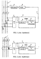
- the scheme of the figure 1 represents a circuit breaker comprising a ground protection device of the prior art.
- an electrical distribution network 1 comprises phase conductors A, B, C and a neutral conductor N.
- phase and neutral currents are carried out with current transformers arranged on each conductor respectively 2A, 2B, 2C and 2N.
- the Current transformers provide phase and neutral signals to a zero-sequence or ground-fault detection circuit 3.
- Generally circuit 3 makes a vector sum to determine the current IG1 representative of a ground fault current.
- the signal IG1 is applied to an input of a processing circuit 4 which comprises a preprocessing module 5 for determining an effective value IGRMS of the signal IG1, and a protection function processing module 6.
- the processing circuit provides a trigger signal 7 if the ground fault signal IG1 exceeds a threshold for a predetermined time.
- the signal 7 is supplied to a relay 8 to control the opening of contacts 10 actuated by a mechanism 9.
- the circuits 3 and 4 and the relay 8 form an electronic trip for a circuit breaker.
- the scheme of the figure 2 shows a different embodiment.
- the value of a ground fault current is measured by a current sensor 11 which surrounds all the phase and neutral conductors.
- the signal supplied by the sensor 11 is applied to a detection circuit 3 which performs, in this case, in particular the shaping and rectification of the signal.
- Circuit 3 supplies a signal IG1 representative of a ground fault current to a processing circuit 4.
- Circuit 4 of the figure 2 comprises a preprocessing module 5 for performing the peak detection of the earth protection signal and provides an IGPIC signal to the protection function processing module 6.
- the duration of said current is short and the pretreatment module in effective value does not correctly detect such a fault.
- a detection directly in effective value reduces the value of the signal and is not representative of the real nuisances that can produce an arc signal. If the detection was in peak value as on the figure 2 the arc currents would then be overestimated and the detection of sinusoidal currents with harmonics would not be accurate.
- the detection of sinusoidal fault current comprising harmonics is precise especially in rms value and the currents comprising pulses of short durations such that the representative arc fault currents are estimated at values greater than those of their effective values.
- the earth protection device comprises a processing module 12 disposed between the detection circuit 3 and a preprocessing module 5.
- the module 12 receives the signal IG1 representative of a ground fault signal and provides a second signal IG2 representative of a ground fault having on decreasing a slope limited to a predetermined value.
- the slope limited to decay is greater than a slope at the decay of a sinusoid.
- the signal IG2 can decrease faster than a sinusoid to preserve the shape of the sinusoidal signals.
- the pretreatment module 5 preferably detects an effective value IGX of the second signal IG2.
- an approximate effective value IGX can also be obtained by filtering or directly integrated into the protection function of the module 6.
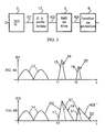
- the Figure 4A shows a corrected IG1 signal representative of a ground fault and the Figure 4B shows an IG2 signal provided by the module 12.
- two first half-waves 13 of the signal IG1 are sinusoidal. If the limited slope is greater than a sinusoidal slope, the signal IG2 has substantially the same shape as the signal IG1. Thus, the first two alternations 14 of the signal IG2 of the Figure 4B look like alternations 13.
- a first signal representative of an arc appears.
- This signal has a high amplitude and a limited duration. In this case, the slope at decay, represented by a portion 16 of the curve, is very high.
- the signal IG2 then has at time t1 a signal 17 corresponding to the signal 15 of the signal IG1.
- the increasing portion of the signal 17 resembles the increasing portion of the signal 15, but a decreasing portion 18 has a decreasing slope limited.
- the signal 17 of IG2 representative of an arc has a longer duration than that of the signal 15 and therefore the effective or average value of IG2 is increased when the signal IG1 is representative of an arc signal.
- a second signal 19 representative of an arc signal appears on IG1.
- This signal also has a slope at very high decay. It will be replaced at output on IG2 by a signal 21 having a slope 22 with limited decay.
- the figure 5 shows an embodiment of a module 12 for a device according to the invention.
- the signal IG1 representative of a homopolar current is applied to the input of a sampling circuit 23 which supplies a sampled signal IG1 (t) to a first input of a maximum detector 24.
- the maximum detector provides a sampled output signal IG2 (t).
- a storage circuit 25 receives and stores the signal IG2 (t) and outputs a sample preceding IG2 (t-1) of the signal IG2 (t).
- a parameterization module 26 provides a value L of the slope of limitation to decay.
- the maximum detector 24 provides the highest signal between the input signal IG1 (t) and the value signal IGL (t) limited to decay. Thus, as soon as the signal IG1 (t) has a slope at the decay that exceeds the limited slope of value L, the detector 24 outputs the signal IGL (t) in place of the signal IG1 (t).
- the figure 6 shows an operating flowchart of a module 12.
- a sampling of the signal IG1 (t) is carried out at a reading step 28.
- the maximum value between IG1 (t) and IGL (t) is assigned to IG2 (t).
- a storage step 31 stores the last value of IG2 (t), thus IG2 (t-1) is equal to IG2 (t).
- the figure 7 shows another embodiment of a module 12.
- the module 12 comprises substantially the same elements as that of the figure 5 .
- a comparator 33 is provided to compare the difference D and the slope limitation value L, and a selector 34 controlled by the comparator provides the output signal IG2 (t).
- the comparator 33 receives the signals IG1 (t) from the sampler 23, the signal IGL (t) of the limitation module 27 controls the selector 34 to apply at the output to the signal IG2 (t) the value IG1 (t) if the difference D is less than the limit L or the value IGL (t) if the difference D is greater than the limit L.
- the figure 8 shows another embodiment of a flowchart that can operate in a module 12.
- This flowchart comprises the 28 reading and 31 storage steps such as that of the figure 6 .
- a comparison step 35 compares the slope limitation value L and the difference D between the stored value IG2 (t-1) and the value of the sample IG1 (t). If the difference is greater than or equal to the value L, a step 36 assigns the output signal IG2 (t) a limiting value such that IG2 (t) is equal to IG2 (t-1) -L. If the difference is less than the value L, a step 37 assigns the output signal IG2 (t) the value of the input signal IG1 (t).
- the slope limitation value L is constant. It can be fixedly predetermined or depend on the last peak value of the ground fault signal IG1.
- the slope limitation value L may be variable as a function of the time which separates it from the last peak of the ground fault signal IG1.
- the slope can be very low near the peak of the signal and become high when the time increases with respect to the last ridge.
- the slope limiting value L may be variable depending on the value of the last peak and the time that separates the samples of IG1 (t) from the last peak of said signal IG1 (t).
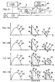
- the figure 9 shows a diagram of a slope value modification device.
- This device comprises a sampling control circuit 38 for controlling the sampler 23 and supplying sampling information S to the parameterization module 26.
- This device also comprises a peak detector 39 receiving the signal IG1 (t) and providing a IGP signal representative of the last peak in the module 26.
- the selection of the type of slope can be performed with a selection module 40 connected to the module 26.
- FIGS 10A and 10D illustrate signals corresponding to different types of decay limiting slopes.
- the slope at decay is different for the signals 42 and 43.
- a slope 46 has a high value
- a slope 47 has a low value.
- the slope may advantageously depend on a last peak 48 of the signal IG1.
- Another advantage of the control of the slope is the control of the time of return to zero of the signal IG2.
- T1 and T2 are different with identical slopes 44 and 45 while on the figure 10B durations T3 and T4 are substantially equivalent with different slopes 46 and 47.
- the slope at the decay is variable as a function of a time between the last peak and a posterior value of the signal IG2.
- the slope has a first value in a portion 49 between instants t5 and t6, a second value in a portion 50 between times t6 and t7, a third value in a portion 51 between times t7 and t8, and a fourth value in a portion 52 between times t8 and t9.
- the instants t5 to t9 can be determined according to the number of samples which separates an instantaneous signal from the instant of the last peak 48.
- the slope at the decay is variable according to a time as in the Figure 10C and also depending on the value of the last peak.
- the portions 49 to 52 may be different at each signal.
- a slope at the decrease according to the figure 10D can simulate a parabolic type curve.
Claims (12)
- Erdschluss-Schutzeinrichtung mit einem Eingang zum Empfang eines ersten, einen Erdfehlerstrom abbildenden Signals (IG1), mit ersten Signalverarbeitungsmitteln (5) zur Verarbeitung eines einen Erdfehlerstrom abbildenden Signals sowie mit an die ersten Signalverarbeitungsmittel (5) angeschlossenen Schutzfunktions-Verarbeitungsmitteln (6), dadurch gekennzeichnet, dass die Einrichtung zwischen den genannten Eingang und die ersten Signalverarbeitungsmittel (5) geschaltete zweite Signalverarbeitungsmittel (12) zur Verarbeitung eines einen Erdfehlerstrom abbildenden Signals (IG1) umfasst, welche genannten zweiten Signalverarbeitungsmittel die ersten Signalverarbeitungsmittel mit einem zweiten, einen Erdfehlerstrom abbildenden Signal (IG2) beaufschlagen, dessen Abfallsteigung (18, 22, 44-47, 49-52) unter einem bestimmten Steigungsbegrenzungswert (L) liegt.
- Erdschluss-Schutzeinrichtung nach Anspruch 1, dadurch gekennzeichnet, dass die zweiten Signalverarbeitungsmittel- Abtastmittel (23) zur Abtastung des ersten, einen Erdfehlerstrom abbildenden Signals,- Speichermittel (25) zur Speicherung eines letzten Werts (IG2(t-1)) des zweiten, einen Erdfehlerstrom abbildenden Signals,- an die Speichermittel sowie an Mittel (26) zur Lieferung eines Steigungsbegrenzungswerts (L) angeschlossene Abfallberechnungsmittel (27) zur Berechnung eines Werts (IGL(t)) mit Abfallbegrenzung, wobei der Wert mit Abfallbegrenzung den letzten Wert (IG2(t-1)) des zweiten, einen Erdfehlerstrom abbildenden Signals, vermindert um den Steigungsbegrenzungswert (L) abbildet,- sowie an die Abtastmittel (23) und die Abfallberechnungsmittel (27, 32, 33, 34) angeschlossene Bestimmungsmittel (24) zur Bestimmung eines neuen Werts des zweiten, einen Erdfehlerstrom abbildenden Signals (IG2(t)) umfasst.
- Erdschluss-Schutzeinrichtung nach Anspruch 2, dadurch gekennzeichnet, dass die Bestimmungsmittel Maximalwert-Detektionsmittel (24) zur Lieferung eines neuen Werts (IG2(t)) des zweiten, einen Erdfehlerstrom abbildenden Signals umfassen, wobei das genannte zweite Signal in Abhängigkeit von einem Maximalwert des ersten Abtastsignals (IG 1 (t)) oder des Werts mit Abfallbegrenzung (IGL(t)) bestimmt wird.
- Erdschluss-Schutzeinrichtung nach einem der Ansprüche 2 oder 3, dadurch gekennzeichnet, dass die Bestimmungsmittel- an die Speichermittel (25) und die Abtastmittel (23) angeschlossene Berechnungsmittel (32) zur Berechnung der Differenz zwischen einem Wert (IG 1 (t)) des ersten Abtastwerts und einem letzten Wert (IG2(t-1)) des zweiten Signals,- Vergleichsmittel (33) zum Vergleich der genannten Differenz (D) mit dem Steigungsbegrenzungswert (L)- sowie Auswahlmittel (34) mit an die Abtastmittel (23) und an die Abfallberechnungsmittel (27) angeschlossenen Eingängen umfassen, welche Auswahlmittel von den Vergleichsmitteln (33) angesteuert werden, um an ihrem Ausgang ein Signal mit einem Abfallbegrenzungswert (IG2(t)) zu liefern, wenn die Differenz zwischen einem Wert (IG1(t) des ersten Abtastsignals und einem letzten Wert (IG2(t-1) des zweiten Signals größer ist als der Steigungsbegrenzungswert (L).
- Erdschluss-Schutzeinrichtung nach irgendeinem der Ansprüche 1 bis 4, dadurch gekennzeichnet, dass der Steigungsbegrenzungswert (L) konstant ist.
- Erdschluss-Schutzeinrichtung nach irgendeinem der Ansprüche 1 bis 5, dadurch gekennzeichnet, dass der Steigungsbegrenzungswert (L) in Abhängigkeit von einem letzten Scheitelwert (IGP) des ersten, einen Erdfehlerstrom abbildenden Signals (IG1) veränderbar ist.
- Erdschluss-Schutzeinrichtung nach irgendeinem der Ansprüche 1 bis 6, dadurch gekennzeichnet, dass der Steigungsbegrenzungswert (L) in Abhängigkeit von einer Zeitspanne (t6, t7, t8, t9) zwischen einem letzten Scheitelwert (48) und einem nachfolgenden Augenblickswert des ersten, einen Erdfehlerstrom abbildenden Signals veränderbar ist.
- Erdschluss-Schutzeinrichtung nach irgendeinem der Ansprüche 2 bis 7, dadurch gekennzeichnet, dass der Steigungsbegrenzungswert (L) in Abhängigkeit von einem letzten Scheitelwert (IGP) und einer Zeitspanne (t6, t7, t8, t9) zwischen einem letzten Scheitelwert und einem nachfolgenden Augenblickswert des ersten, einen Erdfehlerstrom abbildenden Signals veränderbar ist.
- Signalverarbeitungsverfahren für eine Erdschluss-Schutzeinrichtung nach irgendeinem der Ansprüche 2 bis 8, dadurch gekennzeichnet, dass es- einen Leseschritt (28) zum Einlesen eines, einen Erdfehlerstrom abbildenden Eingangssignals (IG1(t)),- einen Bestimmungsschritt (29) zur Bestimmung eines Werts (IGL(t) mit Abfallbegrenzung,- einen Auswahlschritt (30) zur Lieferung eines, einen Erdfehlerstrom abbildenden Ausgangssignals (IG2(t)), welches Ausgangssignal abfallbegrenzt ist, wenn die Differenz zwischen dem Eingangssignal (IG1(t)) und einem vorhergehenden Ausgangssignal (IG2(t-1)) größer ist als ein Begrenzungswert (L),- sowie einen Speicherschritt (31) zur Speicherung des Ausgangssignals umfasst.
- Verfahren nach Anspruch 9, dadurch gekennzeichnet, dass es einen Detektionsschritt (30) zur Erkennung eines Maximalwerts (IG2(t)) zwischen dem Eingangssignal (IG1 (t)) und dem Wert mit Abfallbegrenzung (IGL(t)) umfasst.
- Elektronischer Auslöser mit einer Erdschluss-Schutzeinrichtung nach irgendeinem der Ansprüche 2 bis 8.
- Leistungsschalter mit einer Erdschluss-Schutzeinrichtung nach irgendeinem der Ansprüche 2 bis 8.
Applications Claiming Priority (2)
| Application Number | Priority Date | Filing Date | Title |
|---|---|---|---|
| FR9911489 | 1999-09-10 | ||
| FR9911489A FR2798527B1 (fr) | 1999-09-10 | 1999-09-10 | Dispositif de protection terre sensible a des courants d'arc, declencheur et disjoncteur comportant un tel dispositif |
Publications (2)
| Publication Number | Publication Date |
|---|---|
| EP1083644A1 EP1083644A1 (de) | 2001-03-14 |
| EP1083644B1 true EP1083644B1 (de) | 2010-08-04 |
Family
ID=9549830
Family Applications (1)
| Application Number | Title | Priority Date | Filing Date |
|---|---|---|---|
| EP00410096A Expired - Lifetime EP1083644B1 (de) | 1999-09-10 | 2000-08-11 | Lichtbogenstromsensitiver Erdfehlerschutz, Auslöser und Schutzschalter mit einer solchen Vorrichtung |
Country Status (7)
| Country | Link |
|---|---|
| US (1) | US6437952B1 (de) |
| EP (1) | EP1083644B1 (de) |
| CA (1) | CA2316050C (de) |
| DE (1) | DE60044765D1 (de) |
| FR (1) | FR2798527B1 (de) |
| MX (1) | MXPA00008565A (de) |
| ZA (1) | ZA200004332B (de) |
Families Citing this family (1)
| Publication number | Priority date | Publication date | Assignee | Title |
|---|---|---|---|---|
| FR2798526B1 (fr) * | 1999-09-15 | 2001-11-09 | Schneider Electric Ind Sa | Declencheur electronique avec des moyens de correction d'offset |
Family Cites Families (3)
| Publication number | Priority date | Publication date | Assignee | Title |
|---|---|---|---|---|
| FR2719124B1 (fr) * | 1994-04-21 | 1996-06-07 | Merlin Gerin | Procédé et dispositif de correction d'un signal de courant. |
| US5726577A (en) * | 1996-04-17 | 1998-03-10 | Eaton Corporation | Apparatus for detecting and responding to series arcs in AC electrical systems |
| US5818237A (en) * | 1996-06-10 | 1998-10-06 | Eaton Corporation | Apparatus for envelope detection of low current arcs |
-
1999
- 1999-09-10 FR FR9911489A patent/FR2798527B1/fr not_active Expired - Lifetime
-
2000
- 2000-07-14 US US09/617,124 patent/US6437952B1/en not_active Expired - Lifetime
- 2000-08-11 EP EP00410096A patent/EP1083644B1/de not_active Expired - Lifetime
- 2000-08-11 DE DE60044765T patent/DE60044765D1/de not_active Expired - Lifetime
- 2000-08-16 CA CA2316050A patent/CA2316050C/en not_active Expired - Fee Related
- 2000-08-23 ZA ZA200004332A patent/ZA200004332B/xx unknown
- 2000-09-01 MX MXPA00008565A patent/MXPA00008565A/es active IP Right Grant
Also Published As
| Publication number | Publication date |
|---|---|
| CA2316050A1 (en) | 2001-03-10 |
| DE60044765D1 (de) | 2010-09-16 |
| CA2316050C (en) | 2010-10-12 |
| FR2798527B1 (fr) | 2001-11-09 |
| ZA200004332B (en) | 2001-03-12 |
| MXPA00008565A (es) | 2005-09-08 |
| EP1083644A1 (de) | 2001-03-14 |
| US6437952B1 (en) | 2002-08-20 |
| FR2798527A1 (fr) | 2001-03-16 |
Similar Documents
| Publication | Publication Date | Title |
|---|---|---|
| EP0407310B1 (de) | Festkörperauslöser mit einer Desensibilisierungsvorrichtung für den Erdschutz | |
| EP0396477B1 (de) | Statischer Auslöser für einen ein dreiphasiges Netz schützenden Schutzschalter, der die Bestimmung des Fehlertyps erlaubt | |
| EP2383856B1 (de) | Identifizierung und richtungserfassung eines defekts in einem dreiphasennetz | |
| EP1890165B1 (de) | Verfahren zur Richtungserkennung eines Massefehlers und Vorrichtung zur Umsetzung dieses Verfahrens | |
| EP2687860B1 (de) | Richtungs-Erkennung eines empfindlichen Mittelspannungs-Erdschlusses durch lineare Korrelation | |
| EP1475874A1 (de) | Erdschlussüberwachungssystem und Verfahren und Relais mit einer solchen Einrichtung | |
| EP0568471B1 (de) | Einrichtung zur Überwachung eines homopolaren Fehlers im Stromnetz | |
| EP3384592B1 (de) | Verfahren und vorrichtung zur erkennung von lichtbögen in einer fotovoltaikanlage | |
| EP0053069A1 (de) | Verfahren zur Richtungserkennung einer Störung in einem elektrischen Netz | |
| EP1318586B1 (de) | Vorrichtung und Verfahren zur elektrischen Kurzschlussdetektion und mit dieser Vorrichtung versehener Lastschalter | |
| EP0592337B1 (de) | Elektronischer Auslöser mit Erdschutz | |
| EP1083644B1 (de) | Lichtbogenstromsensitiver Erdfehlerschutz, Auslöser und Schutzschalter mit einer solchen Vorrichtung | |
| EP0605335B1 (de) | Elektronischer Auslöser mit Testgerät | |
| EP0678960B1 (de) | Verfahren und Einrichtung zur Korrektur eines Stromsignals | |
| EP0591011B1 (de) | Einrichtung zum Feststellen von Fehlern auf einem unterirdischen elektrischen Energieverteilungsnetz | |
| EP1357386B1 (de) | Vorrichtung und Verfahren zur Detektion von elektrischen Ladungen und elektrisches Gerät mit einer solchen Anordnung | |
| EP3033760A1 (de) | Verfahren, vorrichtung und computerprogramm zum steuern eines mechatronischen schutzschalters | |
| WO2009144083A1 (fr) | Procede et systeme de detection d'un courant secondaire residuel dans un transformateur de courant dans un reseau electrique haute tension, et de detection de la formation d'un arc dans un disjoncteur | |
| EP0540379A1 (de) | Zentralisierter Differentialschutzschalter | |
| FR2650711A1 (fr) | Relais de commande pour disjoncteur shunt a poles separes | |
| FR2786916A1 (fr) | Dispositif de commande d'un electro-aimant avec entree de commande locale |
Legal Events
| Date | Code | Title | Description |
|---|---|---|---|
| PUAI | Public reference made under article 153(3) epc to a published international application that has entered the european phase |
Free format text: ORIGINAL CODE: 0009012 |
|
| AK | Designated contracting states |
Kind code of ref document: A1 Designated state(s): DE GB IT |
|
| AX | Request for extension of the european patent |
Free format text: AL;LT;LV;MK;RO;SI |
|
| 17P | Request for examination filed |
Effective date: 20010523 |
|
| AKX | Designation fees paid |
Free format text: DE GB IT |
|
| RAP1 | Party data changed (applicant data changed or rights of an application transferred) |
Owner name: SCHNEIDER ELECTRIC INDUSTRIES SAS |
|
| 17Q | First examination report despatched |
Effective date: 20081107 |
|
| RAP1 | Party data changed (applicant data changed or rights of an application transferred) |
Owner name: SCHNEIDER ELECTRIC INDUSTRIES SAS |
|
| GRAP | Despatch of communication of intention to grant a patent |
Free format text: ORIGINAL CODE: EPIDOSNIGR1 |
|
| RIN1 | Information on inventor provided before grant (corrected) |
Inventor name: SUPTITZ, ERIC Inventor name: BLANCHARD, PIERRE |
|
| GRAS | Grant fee paid |
Free format text: ORIGINAL CODE: EPIDOSNIGR3 |
|
| GRAA | (expected) grant |
Free format text: ORIGINAL CODE: 0009210 |
|
| AK | Designated contracting states |
Kind code of ref document: B1 Designated state(s): DE GB IT |
|
| REG | Reference to a national code |
Ref country code: GB Ref legal event code: FG4D Free format text: NOT ENGLISH |
|
| REF | Corresponds to: |
Ref document number: 60044765 Country of ref document: DE Date of ref document: 20100916 Kind code of ref document: P |
|
| PLBE | No opposition filed within time limit |
Free format text: ORIGINAL CODE: 0009261 |
|
| STAA | Information on the status of an ep patent application or granted ep patent |
Free format text: STATUS: NO OPPOSITION FILED WITHIN TIME LIMIT |
|
| 26N | No opposition filed |
Effective date: 20110506 |
|
| REG | Reference to a national code |
Ref country code: DE Ref legal event code: R097 Ref document number: 60044765 Country of ref document: DE Effective date: 20110506 |
|
| REG | Reference to a national code |
Ref country code: DE Ref legal event code: R084 Ref document number: 60044765 Country of ref document: DE |
|
| PGFP | Annual fee paid to national office [announced via postgrant information from national office to epo] |
Ref country code: DE Payment date: 20180730 Year of fee payment: 19 Ref country code: IT Payment date: 20180823 Year of fee payment: 19 |
|
| PGFP | Annual fee paid to national office [announced via postgrant information from national office to epo] |
Ref country code: GB Payment date: 20190814 Year of fee payment: 20 |
|
| REG | Reference to a national code |
Ref country code: DE Ref legal event code: R119 Ref document number: 60044765 Country of ref document: DE |
|
| PG25 | Lapsed in a contracting state [announced via postgrant information from national office to epo] |
Ref country code: DE Free format text: LAPSE BECAUSE OF NON-PAYMENT OF DUE FEES Effective date: 20200303 |
|
| PG25 | Lapsed in a contracting state [announced via postgrant information from national office to epo] |
Ref country code: IT Free format text: LAPSE BECAUSE OF NON-PAYMENT OF DUE FEES Effective date: 20190811 |
|
| REG | Reference to a national code |
Ref country code: GB Ref legal event code: PE20 Expiry date: 20200810 |
|
| PG25 | Lapsed in a contracting state [announced via postgrant information from national office to epo] |
Ref country code: GB Free format text: LAPSE BECAUSE OF EXPIRATION OF PROTECTION Effective date: 20200810 |