EP1083343B1 - Scheibenelement für eine Radschraube - Google Patents
Scheibenelement für eine Radschraube Download PDFInfo
- Publication number
- EP1083343B1 EP1083343B1 EP00116682A EP00116682A EP1083343B1 EP 1083343 B1 EP1083343 B1 EP 1083343B1 EP 00116682 A EP00116682 A EP 00116682A EP 00116682 A EP00116682 A EP 00116682A EP 1083343 B1 EP1083343 B1 EP 1083343B1
- Authority
- EP
- European Patent Office
- Prior art keywords
- disc element
- wheel
- sleeve
- collar
- end region
- Prior art date
- Legal status (The legal status is an assumption and is not a legal conclusion. Google has not performed a legal analysis and makes no representation as to the accuracy of the status listed.)
- Expired - Lifetime
Links
Images

Classifications
-
- F—MECHANICAL ENGINEERING; LIGHTING; HEATING; WEAPONS; BLASTING
- F16—ENGINEERING ELEMENTS AND UNITS; GENERAL MEASURES FOR PRODUCING AND MAINTAINING EFFECTIVE FUNCTIONING OF MACHINES OR INSTALLATIONS; THERMAL INSULATION IN GENERAL
- F16B—DEVICES FOR FASTENING OR SECURING CONSTRUCTIONAL ELEMENTS OR MACHINE PARTS TOGETHER, e.g. NAILS, BOLTS, CIRCLIPS, CLAMPS, CLIPS OR WEDGES; JOINTS OR JOINTING
- F16B43/00—Washers or equivalent devices; Other devices for supporting bolt-heads or nuts
- F16B43/02—Washers or equivalent devices; Other devices for supporting bolt-heads or nuts with special provisions for engaging surfaces which are not perpendicular to a bolt axis or do not surround the bolt
Definitions
- the invention relates to a disc element for a wheel bolt.
- a wheel nut a motor vehicle wheel according to the preamble of claim 1, e.g. out FR-A-610 579 is known.
- FR-PS 1 452 053 is a disc element for a wheel nut of a motor vehicle wheel known that consists of a slotted ring part. This has a plane on the face Support surface for the wheel nut and an opposite rounded area, which in a correspondingly trained rounded trough of a fastening device for the Wheel is arranged. A continuous slot in the disc element has a certain effect Spring action when tightening the wheel nut. From the FR 700.170 there is a screw nut connected to a resilient element, which is supported on a plate. This springy element has a rounded end region, which in a corresponding region of the Plate is arranged.
- the object of the invention is to provide an improved disc element for a wheel bolt or To create a wheel nut that provides an optimal, secure connection between the wheel and the wheel hub causes.
- the main advantages achieved with the invention are that through training the disc element is a resilient and resilient screw connection is made secure attachment of the wheel to the wheel hub. Through this disc element furthermore, loosening and loosening of the screw during operation is excluded. Furthermore, a Stretch length created and a more precise fit.
- the disc element is made of a sleeve part with a rounded end portion consisting, the sleeve part in section a profiled wall with an inside sleeve extension or has an outside sleeve constriction.
- the disc element consists of a c-shaped profile in section, with a partial inside sleeve extension is provided, which is opposite the rounded end region narrowing collar is formed.
- inside sleeve extension can be cylindrical, the end regions of the collar oriented inwards up to the screw shaft form, and the collar forms the rounded end portion.
- the inside Sleeve expansion is conical and the smaller diameter of the cone is in the rounded end area, the other end area one to Screw shaft forms inward collar and supports the screw.
- the sleeve constriction the disc element consists of at least one outer annular groove and this between an outward-facing collar and the rounded one End area is located.
- the disc element can also consist of a cylindrical sleeve part exist at which the rounded end portion with an inward Collar connects.
- the cylindrical sleeve part is according to a first embodiment provided with an extension on the inside, whereby in a further version the cylindrical sleeve part is tapered inside and outside in the wall and one inside expansion and an outside constriction results.
- All embodiments of the disc elements have a rounded End area, which lies in a correspondingly rounded recess of the wheel and thus an exact centering of the wheel is achieved.
- the disc elements are preferably made of a steel material and lie with them its rounded end area, for example with an aluminum wheel, with the entire rounded surface area of the disc element in a corresponding recess of the wheel.
- a steel wheel on the other hand, there is only a smaller area of the rounded end portion of the disc element in the recess of the wheel.
- the spring preload achieved when the bolts are inserted becomes essential achieved by the shape of the disc element, the design with a C-shaped profile causes greater spring preload than the cylindrical Designs of the disc element.
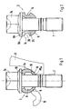
- a disc element 1; 2; 3; 4; 5; 6 for a wheel bolt essentially comprises a sleeve part 1a, 2a; 3a; 4a; 5a; 6a with a rounded end region 8, wherein the sleeve part in section a profiled wall with a sleeve extension 9; 10; 11; 12; 13 and / or with a sleeve constriction 14; 15 has.
- the disc element is with its rounded end region 8 in a suitably designed recess 16 of the wheel 17 or 18 used.
- the wheel bolt 7 penetrates the disc element, the screw head 7a at the opposite end of the rounded end region 8 on a collar 8b supports.
- the diameters D and D1 of the holes 19 and 20 in the Disc elements are somewhat larger than that with a certain play Executed screw diameter.
- the disk elements 1 and 4 have approximately the same shape and consist of a sleeve part 1a; 4a with an average c-shaped profile, which is a partial inside sleeve extension 9; 11 has.
- the further disc element 3 is also with a c-shaped profile and has one Sleeve extension 10 on.
- the inner sleeve extension 10 executed cylindrical.
- the end regions 8 and 8a of this element 3 emulate a collar 8b, 8c oriented toward the screw shaft, the collar 8b supports the screw head 7a and the collar 8c supports the rounded end region 8 forms.
- annular groove 20 can also have a different geometric cross-sectional shape have as shown, for example triangular or as a segment of a circle.
Landscapes
- Engineering & Computer Science (AREA)
- General Engineering & Computer Science (AREA)
- Mechanical Engineering (AREA)
- Bolts, Nuts, And Washers (AREA)
- Connection Of Plates (AREA)
- Dowels (AREA)
- Braking Arrangements (AREA)
Description
- Fig. 1
- eine Ansicht auf ein c-profilförmiges Scheibenelement mit innenliegender Erweiterung im Schnitt mit Radbolzen in einem Stahlrad und in einem Alurad eingesetzt,
- Fig. 2
- eine weitere Ausführung eines Scheibenelementes mit äußerer Einschnürung und eingesetztem Radbolzen,
- Fig. 3
- ein c-profilförmiges Scheibenelement im Schnitt mit einer inneren zylindrischen Erweiterung im Hülsenteil,
- Fig. 4
- eine Ausführung eines c-profilförmigen Scheibenelementes im Schnitt ähnlich der Ausführung gem. Fig. 1 als Einzelteil dargestellt,
- Fig. 5
- eine weitere Ausführung eines c-profilförmigen Scheibenelementes im Schnitt mit einer äußeren Einschnürung.
Claims (4)
- Scheibenelement für eine Radschraube (7) eines Kraftfahrzeugrades, das mit seinem einen Ende teilweise in einer ausgerundeten Mulde (16) an der Befestigungsbohrung für das Rad angeordnet ist und mit seinem anderen Ende an der Radschraube (7) abgestützt ist, und das Scheibenelement (1; 2; 3; 4) aus einem Hülsenteil (1a; bis 4a) mit einem der Mulde (16) zugerichteten ausgerundet ausgebildeten Endbereich (8) und einer im Schnitt profilierten Wandung besteht, dadurch gekennzeichnet, daß das Hülsenteil (1a; 2a; 3a; 4a) des Scheibenelements (1, 2, 3) aus einem im Querschnitt etwa C-förmigen Profil besteht, welche eine innenseitige Hülsenerweiterung (9; 10; 11) oder einer außenseitigen Hülseneinschiebung (14) aufweist, die einen dem ausgerundeten Endbereich (8) gegenüberstehenden nach innen gerichteten verengenden Kragen (8c; 8d) oder nach auswärts gerichteten Kragen (8b) besitzt.
- Scheibenelement nach Anspruch 1, dadurch gekennzeichnet, daß die innenseitige Hülsenerweiterung (9; 10) etwa zylinderförmig ausgeführt ist und die Endbereiche (8; 8a) den nach einwärts bis zum Schraubenschaft ausgerichteten Kragen (8c und 8d) bilden, wob ei der eine Kragen (8c) im ausgerundeten Endbereich (8) liegt.
- Scheibenelement nach den Anspruch 1, dadurch gekennzeichnet, daß die innenseitige Hülsenerweiterung (9; 10) etwa kegelförmig ausgeführt ist und der kleinere Durchmesser des Kegels im ausgerundeten Endbereich (8) liegt und der andere, gegenüberstehende Endbereiche (8a) den zum Schraubenschaft einwärts gerichteten Kragen (8d) bildet.
- Scheibenelement nach den Anspruch 1, dadurch gekennzeichnet, daß die Hülseneinschnürung 14 des Scheibenelements (2) aus wenigstens einer außenseitigen Ringnut (20) besteht und diese sich zwischen dem nach auswärts gerichteten Kragen (8b) und dem ausgerundeten Endbereich (8) befindet.
Applications Claiming Priority (2)
| Application Number | Priority Date | Filing Date | Title |
|---|---|---|---|
| DE19942836 | 1999-09-08 | ||
| DE19942836A DE19942836C2 (de) | 1999-09-08 | 1999-09-08 | Scheibenelement für eine Radschraube bzw. Radmutter eines Kraftfahrzeuges |
Publications (3)
| Publication Number | Publication Date |
|---|---|
| EP1083343A2 EP1083343A2 (de) | 2001-03-14 |
| EP1083343A3 EP1083343A3 (de) | 2002-06-05 |
| EP1083343B1 true EP1083343B1 (de) | 2004-11-03 |
Family
ID=7921186
Family Applications (1)
| Application Number | Title | Priority Date | Filing Date |
|---|---|---|---|
| EP00116682A Expired - Lifetime EP1083343B1 (de) | 1999-09-08 | 2000-08-02 | Scheibenelement für eine Radschraube |
Country Status (5)
| Country | Link |
|---|---|
| US (1) | US6478521B1 (de) |
| EP (1) | EP1083343B1 (de) |
| AT (1) | ATE281314T1 (de) |
| DE (2) | DE19942836C2 (de) |
| ES (1) | ES2226672T3 (de) |
Families Citing this family (13)
| Publication number | Priority date | Publication date | Assignee | Title |
|---|---|---|---|---|
| DE19931837B4 (de) * | 1999-07-09 | 2006-05-11 | OBE OHNMACHT & BAUMGäRTNER GMBH & CO. KG | Schraubverbindung für Scharnierteile |
| US7127593B2 (en) * | 2001-06-11 | 2006-10-24 | Broadcom Corporation | Conditional execution with multiple destination stores |
| US7861071B2 (en) * | 2001-06-11 | 2010-12-28 | Broadcom Corporation | Conditional branch instruction capable of testing a plurality of indicators in a predicate register |
| US6986025B2 (en) * | 2001-06-11 | 2006-01-10 | Broadcom Corporation | Conditional execution per lane |
| DE20317196U1 (de) * | 2003-11-05 | 2004-01-15 | A. Agrati S.P.A., Veduggio Con Colzano | Radschraubenanordnung für PKW oder sonstige Fahrzeuge |
| US20070098524A1 (en) * | 2005-10-31 | 2007-05-03 | Dunlap William L | Conical nut |
| DE102006032142A1 (de) * | 2006-07-12 | 2008-01-24 | Dr.Ing.H.C. F. Porsche Ag | Felge |
| US20080166202A1 (en) * | 2007-01-08 | 2008-07-10 | Dunlap William L | Conical nut |
| US8308247B2 (en) | 2010-07-08 | 2012-11-13 | Accuride Emi, Llc | Wheel mounting sleeve |
| SE537380C2 (sv) * | 2013-07-05 | 2015-04-14 | Scania Cv Ab | Reaktionsstag med en deformerbar bussning |
| US10982707B2 (en) | 2018-08-21 | 2021-04-20 | Goodrich Corporation | Tie bolt retention |
| US12140175B2 (en) * | 2022-01-27 | 2024-11-12 | Ford Global Technologies, Llc | Fastener with alignment bushing |
| DE102024205874A1 (de) * | 2024-06-25 | 2026-01-08 | Volkswagen Aktiengesellschaft | Anordnung zum Befestigen eines Fahrzeugteils an einem Fahrzeug, Befestigungselement, Fahrzeugteil und Fahrzeug |
Family Cites Families (12)
| Publication number | Priority date | Publication date | Assignee | Title |
|---|---|---|---|---|
| FR610579A (fr) * | 1927-04-05 | 1926-09-08 | Perfectionnements aux écrous pour roues amovibles | |
| US1828340A (en) * | 1929-09-03 | 1931-10-20 | Budd Wheel Co | Hub construction |
| FR700170A (fr) * | 1930-08-07 | 1931-02-25 | Michelin & Cie | Perfectionnements aux écrous |
| US2017114A (en) * | 1932-03-02 | 1935-10-15 | Motor Wheel Corp | Clamping-nut assembly |
| US2217086A (en) * | 1936-01-02 | 1940-10-08 | Motor Wheel Corp | Vehicle wheel |
| FR1452053A (fr) * | 1965-05-04 | 1966-02-25 | Michelin & Cie | Attache de roue de véhicule |
| DE6752836U (de) * | 1968-09-23 | 1969-03-13 | Kronprinz Ag | Zentrierende fahrzeugradbefestigung fuer einteilige radscheiben von fahrzeugraedern |
| US4138198A (en) * | 1977-07-18 | 1979-02-06 | General Motors Corporation | Tapered shank ball stud assembly with collapsible washer |
| US4289061A (en) * | 1977-10-03 | 1981-09-15 | Hooker Chemicals & Plastics Corp. | Device and assembly for mounting parts |
| GB8405204D0 (en) * | 1984-02-29 | 1984-04-04 | Exotech Ltd | Fastener spring device |
| DE29614320U1 (de) * | 1996-08-21 | 1996-11-21 | Dr.Ing.H.C. F. Porsche Ag, 70435 Stuttgart | Radschraube |
| US6030161A (en) * | 1998-06-23 | 2000-02-29 | Textron, Inc. | Sleeve and captive bolt assembly |
-
1999
- 1999-09-08 DE DE19942836A patent/DE19942836C2/de not_active Expired - Fee Related
-
2000
- 2000-08-02 EP EP00116682A patent/EP1083343B1/de not_active Expired - Lifetime
- 2000-08-02 ES ES00116682T patent/ES2226672T3/es not_active Expired - Lifetime
- 2000-08-02 AT AT00116682T patent/ATE281314T1/de not_active IP Right Cessation
- 2000-08-02 DE DE50008488T patent/DE50008488D1/de not_active Expired - Lifetime
- 2000-09-07 US US09/657,239 patent/US6478521B1/en not_active Expired - Fee Related
Also Published As
| Publication number | Publication date |
|---|---|
| US6478521B1 (en) | 2002-11-12 |
| ATE281314T1 (de) | 2004-11-15 |
| DE19942836C2 (de) | 2003-04-17 |
| EP1083343A3 (de) | 2002-06-05 |
| DE50008488D1 (de) | 2004-12-09 |
| EP1083343A2 (de) | 2001-03-14 |
| DE19942836A1 (de) | 2001-03-22 |
| ES2226672T3 (es) | 2005-04-01 |
Similar Documents
| Publication | Publication Date | Title |
|---|---|---|
| EP3191313B1 (de) | Fahrzeugrad mit einer radfelge und einer radscheibe | |
| EP2532568B1 (de) | Vorrichtung zur Befestigung eines Anbauteils, zum Beispiel einer Reling, an einer Fahrzeugkarosserie | |
| EP3212433B1 (de) | Fahrzeugrad mit einer verbindung zwischen einer radfelge und einer radscheibe und verfahren zu dessen herstellung | |
| DE19942836C2 (de) | Scheibenelement für eine Radschraube bzw. Radmutter eines Kraftfahrzeuges | |
| EP3509872B1 (de) | Mehrteiliges, gefedertes schienenrad | |
| DE2246517A1 (de) | Bremsscheibe fuer schienenfahrzeuge | |
| DE102005009721B3 (de) | Lageranordnung | |
| DE3138534C2 (de) | ||
| EP0406801B1 (de) | Befestigungselement | |
| DE4123583C2 (de) | Zweiteiliges Fahrzeugrad | |
| DE202021101794U1 (de) | Fahrzeugrad, insbesondere für Nutzfahrzeuge, mit aerodynamischer Abdeckung und aerodynamische Abdeckung für Fahrzeugräder insbesondere von Nutzfahrzeugen | |
| DE10047980C2 (de) | Radbremsscheibe für eine Schienenfahrzeugbremse | |
| DE3316759C1 (de) | Geräuschgedämpftes Schienenrad | |
| EP3921182B1 (de) | Einsatzelement für ein fahrzeugrad sowie fahrzeugrad mit zumindest einem solchen einsatzelement | |
| EP0457249B1 (de) | Anhängerkupplung Stichwort: Verliersicherung mit Wackelabstand | |
| EP0014483B1 (de) | Bremsscheibe, insbesondere für Schienenfahrzeuge | |
| EP1335144B1 (de) | Bremsträgeranordnung | |
| DE10339431B4 (de) | Radbolzen für die Befestigung eines Fahrzeugrades | |
| DE2828137A1 (de) | Halterung fuer bremsscheiben, insbesondere von schienenfahrzeugen | |
| DE102016123370A1 (de) | Bremsscheibe | |
| EP3323629B1 (de) | Radlageranordnung | |
| EP0995914A2 (de) | Befestigungselement aus Metall mit Innengewinde für die Durchsteckmontage | |
| EP4094953B1 (de) | Fahrzeugfelge mit anschlusselement für eine haltevorrichtung zur anbringung einer gleitschutzvorrichtung | |
| CH666004A5 (de) | Geraeuschgedaempftes schienenrad. | |
| DE19742740B4 (de) | Vorrichtung zum Verbinden einer Radnabe mit einer Antriebswelle |
Legal Events
| Date | Code | Title | Description |
|---|---|---|---|
| PUAI | Public reference made under article 153(3) epc to a published international application that has entered the european phase |
Free format text: ORIGINAL CODE: 0009012 |
|
| AK | Designated contracting states |
Kind code of ref document: A2 Designated state(s): AT BE CH CY DE DK ES FI FR GB GR IE IT LI LU MC NL PT SE |
|
| AX | Request for extension of the european patent |
Free format text: AL;LT;LV;MK;RO;SI |
|
| PUAL | Search report despatched |
Free format text: ORIGINAL CODE: 0009013 |
|
| AK | Designated contracting states |
Kind code of ref document: A3 Designated state(s): AT BE CH CY DE DK ES FI FR GB GR IE IT LI LU MC NL PT SE |
|
| AX | Request for extension of the european patent |
Free format text: AL;LT;LV;MK;RO;SI |
|
| RIC1 | Information provided on ipc code assigned before grant |
Free format text: 7B 60B 3/16 A, 7F 16B 43/00 B |
|
| 17P | Request for examination filed |
Effective date: 20021205 |
|
| AKX | Designation fees paid |
Designated state(s): AT BE CH CY DE DK ES FI FR GB GR IE IT LI LU MC NL PT SE |
|
| 17Q | First examination report despatched |
Effective date: 20030821 |
|
| GRAP | Despatch of communication of intention to grant a patent |
Free format text: ORIGINAL CODE: EPIDOSNIGR1 |
|
| GRAS | Grant fee paid |
Free format text: ORIGINAL CODE: EPIDOSNIGR3 |
|
| GRAA | (expected) grant |
Free format text: ORIGINAL CODE: 0009210 |
|
| AK | Designated contracting states |
Kind code of ref document: B1 Designated state(s): AT BE CH CY DE DK ES FI FR GB GR IE IT LI LU MC NL PT SE |
|
| PG25 | Lapsed in a contracting state [announced via postgrant information from national office to epo] |
Ref country code: FI Free format text: LAPSE BECAUSE OF FAILURE TO SUBMIT A TRANSLATION OF THE DESCRIPTION OR TO PAY THE FEE WITHIN THE PRESCRIBED TIME-LIMIT Effective date: 20041103 Ref country code: NL Free format text: LAPSE BECAUSE OF FAILURE TO SUBMIT A TRANSLATION OF THE DESCRIPTION OR TO PAY THE FEE WITHIN THE PRESCRIBED TIME-LIMIT Effective date: 20041103 Ref country code: IE Free format text: LAPSE BECAUSE OF FAILURE TO SUBMIT A TRANSLATION OF THE DESCRIPTION OR TO PAY THE FEE WITHIN THE PRESCRIBED TIME-LIMIT Effective date: 20041103 |
|
| REG | Reference to a national code |
Ref country code: GB Ref legal event code: FG4D Free format text: NOT ENGLISH |
|
| REG | Reference to a national code |
Ref country code: SE Ref legal event code: TRGR |
|
| REG | Reference to a national code |
Ref country code: CH Ref legal event code: EP |
|
| REF | Corresponds to: |
Ref document number: 50008488 Country of ref document: DE Date of ref document: 20041209 Kind code of ref document: P |
|
| REG | Reference to a national code |
Ref country code: IE Ref legal event code: FG4D Free format text: GERMAN |
|
| GBT | Gb: translation of ep patent filed (gb section 77(6)(a)/1977) |
Effective date: 20041203 |
|
| PG25 | Lapsed in a contracting state [announced via postgrant information from national office to epo] |
Ref country code: GR Free format text: LAPSE BECAUSE OF FAILURE TO SUBMIT A TRANSLATION OF THE DESCRIPTION OR TO PAY THE FEE WITHIN THE PRESCRIBED TIME-LIMIT Effective date: 20050203 Ref country code: DK Free format text: LAPSE BECAUSE OF FAILURE TO SUBMIT A TRANSLATION OF THE DESCRIPTION OR TO PAY THE FEE WITHIN THE PRESCRIBED TIME-LIMIT Effective date: 20050203 |
|
| REG | Reference to a national code |
Ref country code: ES Ref legal event code: FG2A Ref document number: 2226672 Country of ref document: ES Kind code of ref document: T3 |
|
| NLV1 | Nl: lapsed or annulled due to failure to fulfill the requirements of art. 29p and 29m of the patents act | ||
| REG | Reference to a national code |
Ref country code: IE Ref legal event code: FD4D |
|
| PG25 | Lapsed in a contracting state [announced via postgrant information from national office to epo] |
Ref country code: CY Free format text: LAPSE BECAUSE OF FAILURE TO SUBMIT A TRANSLATION OF THE DESCRIPTION OR TO PAY THE FEE WITHIN THE PRESCRIBED TIME-LIMIT Effective date: 20050802 Ref country code: LU Free format text: LAPSE BECAUSE OF NON-PAYMENT OF DUE FEES Effective date: 20050802 |
|
| ET | Fr: translation filed | ||
| PG25 | Lapsed in a contracting state [announced via postgrant information from national office to epo] |
Ref country code: LI Free format text: LAPSE BECAUSE OF NON-PAYMENT OF DUE FEES Effective date: 20050831 Ref country code: BE Free format text: LAPSE BECAUSE OF NON-PAYMENT OF DUE FEES Effective date: 20050831 Ref country code: CH Free format text: LAPSE BECAUSE OF NON-PAYMENT OF DUE FEES Effective date: 20050831 Ref country code: MC Free format text: LAPSE BECAUSE OF NON-PAYMENT OF DUE FEES Effective date: 20050831 |
|
| PLBE | No opposition filed within time limit |
Free format text: ORIGINAL CODE: 0009261 |
|
| STAA | Information on the status of an ep patent application or granted ep patent |
Free format text: STATUS: NO OPPOSITION FILED WITHIN TIME LIMIT |
|
| 26N | No opposition filed |
Effective date: 20050804 |
|
| REG | Reference to a national code |
Ref country code: CH Ref legal event code: PL |
|
| PGFP | Annual fee paid to national office [announced via postgrant information from national office to epo] |
Ref country code: ES Payment date: 20070830 Year of fee payment: 8 |
|
| PGFP | Annual fee paid to national office [announced via postgrant information from national office to epo] |
Ref country code: AT Payment date: 20070816 Year of fee payment: 8 |
|
| BERE | Be: lapsed |
Owner name: *HCF PORSCHE A.G. Effective date: 20050831 |
|
| PG25 | Lapsed in a contracting state [announced via postgrant information from national office to epo] |
Ref country code: PT Free format text: LAPSE BECAUSE OF NON-PAYMENT OF DUE FEES Effective date: 20050403 |
|
| PGFP | Annual fee paid to national office [announced via postgrant information from national office to epo] |
Ref country code: SE Payment date: 20070815 Year of fee payment: 8 |
|
| PGFP | Annual fee paid to national office [announced via postgrant information from national office to epo] |
Ref country code: GB Payment date: 20080821 Year of fee payment: 9 |
|
| EUG | Se: european patent has lapsed | ||
| PG25 | Lapsed in a contracting state [announced via postgrant information from national office to epo] |
Ref country code: AT Free format text: LAPSE BECAUSE OF NON-PAYMENT OF DUE FEES Effective date: 20080802 |
|
| REG | Reference to a national code |
Ref country code: ES Ref legal event code: PC2A |
|
| REG | Reference to a national code |
Ref country code: FR Ref legal event code: TP |
|
| REG | Reference to a national code |
Ref country code: ES Ref legal event code: FD2A Effective date: 20080804 |
|
| REG | Reference to a national code |
Ref country code: FR Ref legal event code: CD |
|
| PG25 | Lapsed in a contracting state [announced via postgrant information from national office to epo] |
Ref country code: ES Free format text: LAPSE BECAUSE OF NON-PAYMENT OF DUE FEES Effective date: 20080804 |
|
| GBPC | Gb: european patent ceased through non-payment of renewal fee |
Effective date: 20090802 |
|
| PG25 | Lapsed in a contracting state [announced via postgrant information from national office to epo] |
Ref country code: SE Free format text: LAPSE BECAUSE OF NON-PAYMENT OF DUE FEES Effective date: 20080803 |
|
| PG25 | Lapsed in a contracting state [announced via postgrant information from national office to epo] |
Ref country code: GB Free format text: LAPSE BECAUSE OF NON-PAYMENT OF DUE FEES Effective date: 20090802 |
|
| REG | Reference to a national code |
Ref country code: FR Ref legal event code: TP |
|
| REG | Reference to a national code |
Ref country code: FR Ref legal event code: PLFP Year of fee payment: 16 |
|
| PGFP | Annual fee paid to national office [announced via postgrant information from national office to epo] |
Ref country code: DE Payment date: 20150730 Year of fee payment: 16 |
|
| PGFP | Annual fee paid to national office [announced via postgrant information from national office to epo] |
Ref country code: FR Payment date: 20150820 Year of fee payment: 16 |
|
| PGFP | Annual fee paid to national office [announced via postgrant information from national office to epo] |
Ref country code: IT Payment date: 20150824 Year of fee payment: 16 |
|
| REG | Reference to a national code |
Ref country code: DE Ref legal event code: R119 Ref document number: 50008488 Country of ref document: DE |
|
| REG | Reference to a national code |
Ref country code: FR Ref legal event code: ST Effective date: 20170428 |
|
| PG25 | Lapsed in a contracting state [announced via postgrant information from national office to epo] |
Ref country code: DE Free format text: LAPSE BECAUSE OF NON-PAYMENT OF DUE FEES Effective date: 20170301 Ref country code: FR Free format text: LAPSE BECAUSE OF NON-PAYMENT OF DUE FEES Effective date: 20160831 |
|
| PG25 | Lapsed in a contracting state [announced via postgrant information from national office to epo] |
Ref country code: IT Free format text: LAPSE BECAUSE OF NON-PAYMENT OF DUE FEES Effective date: 20160802 |