EP1083119A2 - Body structure for vehicle - Google Patents
Body structure for vehicle Download PDFInfo
- Publication number
- EP1083119A2 EP1083119A2 EP00307107A EP00307107A EP1083119A2 EP 1083119 A2 EP1083119 A2 EP 1083119A2 EP 00307107 A EP00307107 A EP 00307107A EP 00307107 A EP00307107 A EP 00307107A EP 1083119 A2 EP1083119 A2 EP 1083119A2
- Authority
- EP
- European Patent Office
- Prior art keywords
- panel
- reinforcement member
- wall
- vehicle
- lateral end
- Prior art date
- Legal status (The legal status is an assumption and is not a legal conclusion. Google has not performed a legal analysis and makes no representation as to the accuracy of the status listed.)
- Granted
Links
Images


Classifications
-
- B—PERFORMING OPERATIONS; TRANSPORTING
- B62—LAND VEHICLES FOR TRAVELLING OTHERWISE THAN ON RAILS
- B62D—MOTOR VEHICLES; TRAILERS
- B62D25/00—Superstructure or monocoque structure sub-units; Parts or details thereof not otherwise provided for
- B62D25/08—Front or rear portions
- B62D25/082—Engine compartments
-
- B—PERFORMING OPERATIONS; TRANSPORTING
- B62—LAND VEHICLES FOR TRAVELLING OTHERWISE THAN ON RAILS
- B62D—MOTOR VEHICLES; TRAILERS
- B62D21/00—Understructures, i.e. chassis frame on which a vehicle body may be mounted
- B62D21/10—Understructures, i.e. chassis frame on which a vehicle body may be mounted in which the main member is plate-like
-
- B—PERFORMING OPERATIONS; TRANSPORTING
- B62—LAND VEHICLES FOR TRAVELLING OTHERWISE THAN ON RAILS
- B62D—MOTOR VEHICLES; TRAILERS
- B62D27/00—Connections between superstructure or understructure sub-units
- B62D27/02—Connections between superstructure or understructure sub-units rigid
-
- B—PERFORMING OPERATIONS; TRANSPORTING
- B62—LAND VEHICLES FOR TRAVELLING OTHERWISE THAN ON RAILS
- B62D—MOTOR VEHICLES; TRAILERS
- B62D29/00—Superstructures, understructures, or sub-units thereof, characterised by the material thereof
- B62D29/008—Superstructures, understructures, or sub-units thereof, characterised by the material thereof predominantly of light alloys, e.g. extruded
Definitions
- the present invention relates to a body structure for vehicle. Particularly, it relates to the (vehicle) body structure around a dash panel which separates a vehicle cabin and a front compartment or a rear compartment of the vehicle.
- the positioning of the respective body panel members is carried out by attaching them to body jigs prescribing the relative positions of the members. Further, the welding operation of the panel members to be welded is performed on condition that the members are pinched by respective clamping jigs for temporarily holding (see Japanese Unexamined Patent Publications Nos. 10-264862 and 7-309254).
- the vehicle body by plural panel members consisting of extrusions or castings of lightweight metal, such as aluminum alloy, in place of the press moldings, in view of making the lightweight vehicle body compatible with its rigidity.
- a vehicle body structure where a dash panel separating the vehicle cabin and the front compartment (or the rear compartment) consists of an extrusion having an improved rigidity.
- the extrusion is provided with a closed sectional structure having inner and outer walls and obtained by extruding the above lightweight metal to the vehicle's width direction.
- the so-constructed dash panel is reinforced by a reinforcement member which is made of a casting of lightweight metal and connected to the under face of the dash panel.
- the above-mentioned positioning jigs and the clamping jigs have been still required to connect the dash panel with the reinforcement member in spite of such the measures for the lightweight vehicle body compatible with its rigidity. It means that the above-mentioned assembling form causes enormous number of positioning and clamping jigs to be required every sort of vehicles and every process. Consequently, with the addition of installation cost and steps of setting the jigs, the labor cost is apt to increase disadvantageously.
- a vehicle body structure for vehicle comprising:
- a vehicle comprising:
- the above-mentioned object is also accomplished by a method of assembling the above vehicle body structure of the invention, the method comprising:
- Figure 1 illustrates a vehicle body VB which includes a dash panel (also known as dash cross member) 1 and a reinforcement member 4 constituting the vehicle body structure of the invention.
- the dash panel 2 is connected with the front end of a floor panel 3.
- a pair of front side members 6 which project in front.
- the leading ends of the front side members 6 are together connected with a first cross member 32 extending along the direction along the width of the vehicle body VB. Note that this direction will be referred as “vehicle width direction” or “width-direction”, hereinafter.
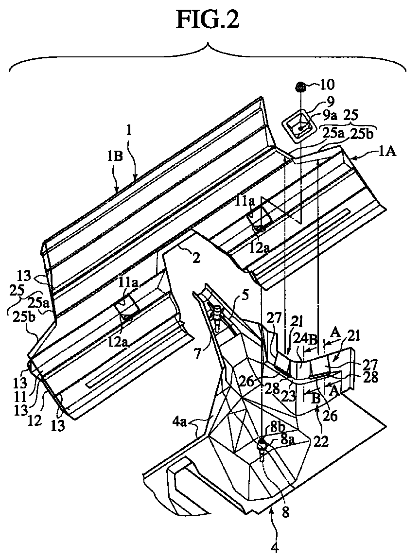
- Figs. 2 and 3 show the dash panel 1 which defines a front compartment FC for accepting a not-shown automotive power unit (e.g. engine) in front of a vehicle cabin R.
- the dash panel 1 includes an inclined toe board 1A and a vertical wall part 1B rising generally perpendicularly from the board 1A.
- the dash panel 1 has a tunnel fitting part (notch) 2 arranged at the center of the toe board 1A in the vehicle width direction, for fitting with a tunnel part 3A of the floor panel 3. On condition that the tunnel part 3A of the floor panel 3 is fitted into the notch 2 and the front end of the floor panel 3 overlaps with the rear part of the toe board 1A, the dash panel 1 is fixed to the floor panel 3 by welding.
- notch tunnel fitting part
- the reinforcement member 4 is joined to the underside of the dash panel 1, extending from the toe board 1A to the vertical wall part 1B.
- the reinforcement member 4 is provided, on left and right sides thereof, with a pair of arm parts 5 which extend forward. As shown in Fig. 3, respective rear ends of the above front side members 6 and a pair of braces 6A are together welded to the arm parts 5 of the reinforcement member 4.
- the dash panel 1 can be provided by an extrusion of lightweight metallic material, such as aluminum alloy, in the vehicle width direction.
- the dash panel 1 is formed with a closed sectional structure having an inner wall 11 and an outer wall 12. Interposed between the inner wall 11 and the outer wall 12 are a plurality of rib walls 13 which also extend to the vehicle width direction, thereby enhancing the rigidity of the panel 1 itself.
- the floor panel 3 is also obtained by extruding similar lightweight metallic material in a direction of both in front and in the rear of the vehicle body VB.
- the floor panel 3 is provided with a closed sectional structure having an inner wall 14, an outer wall 15, and a plurality of rib walls 16.
- a pair of side sills 3B are formed integrally with both sides of the panel 3, respectively. Note the above direction will be referred to "vehicle front/behind direction" or “front/behind-direction” , hereinafter.
- a casting of the above lightweight metallic material constitutes the reinforcement member 4.
- the member 4 is provided, on its each side in the vehicle width direction, with a pair of suspension mount bolts 7, 8 which project downward. Being partially inserted into the casting, the suspension mount bolt 7 is positioned in the vicinity of the front end of each arm part 5, while the suspension mount bolt 8 is positioned at the main part of the reinforcement member 4. These bolts 7, 8 are connected with a not-shown suspension member for supporting a front suspension.
- the rear suspension mount bolt 8 has a tapered locating pin 8a formed to project into the vehicle cabin R and a screw part 8b formed on the end of the locating pin 8a.
- the locating pin 8a of the bolt 8 is inserted into a locating hole 12a in the outer wall 12 of the dash panel 1.
- a lid-shaped retainer plate 9 is fitted to an opening 11a in the inner wall 11 of the dash panel 1.
- the screw part 8b of the bolt 8 is inserted into a through hole 9a in the retainer plate 9 and further tightened by a nut 10 in screw engagement. In this way, the rear end of the suspension member is firmly fastened by the walls 11, 12 of the dash panel 1.
- the reinforcement member 4 is provided, on its both sides in the vehicle width direction, with engagement parts (clip parts) 21 for pinching both ends of the dash panel 1 in the vehicle width direction (two parts 21 on one side shown in Fig. 2).
- the engagement parts 21 serve to position the reinforcement member 4 and the dash panel 1 mutually and retain the dash panel 1 on the reinforcement member 4 temporarily.
- the reinforcement member 4 has positioning parts 22 arranged on both ends of the member 4 in the vehicle width direction (only one shown in the figure).
- Each positioning part 22 consists of a shelf portion 23 for mounting the dash panel's end in the vehicle width direction and a flange portion 24 rising from the shelf portion 23.
- the above engagement parts 21 are arranged in the flange portion 24 and also between the shelf portion 23 and the flange portion 24.
- substantially L-shaped notches 25 are respectively defined in the dash panel 1 to extend from the upper side of the toe board 1A to the top end of the vertical wall part 1B, corresponding to respective wheel-housing structures (not shown) of the vehicle.
- the positioning parts 22 are also formed to have substantially L-shaped profiles in plan view.
- two engagement parts 21 are arranged in respective positions corresponding to an edge 25a in the vehicle width direction and another edge 25b in the vehicle front/behind direction, both edges 25a, 25b defining the L-shaped notch 25.
- each engagement part 21 has a flat part 26 (the part of shelf 23), a taper face 27 and a slot 28.
- the flat part 26 is arranged for abutment with the under face of the outer wall 15 of the dash panel 1.
- the taper face 27 is slanted to the flat part 26 at an open angle ⁇ 2 (Fig. 4) larger than an open angle ⁇ 1 (Fig. 6) of an inside generalized face 24a of the flange portion 24, allowing the engagement part 21 in slide contact with respective ends of the inner and outer walls 11, 12.
- the slot 28 is formed in a position between the flat part 26 and the taper face 27, for engagement with an end 12a of the outer wall 12 of the dash panel 1.
- this slot 28 is provided by using a drill 29 capable of drilling the reinforcement member 4 at a proper angle ⁇ 3 and a designated length.
- the angle ⁇ 3 substantially corresponds to one that bisects an angle interposed between the flat part 26 and the taper face 27.
- the slot 28 is provided with an upper face 28a and an lower face 28b as slanted surfaces.
- the flange portion 24 is provided, in its part profiled by the taper face 27, with a wall thickness that is gradually thickened from the top to the flat part 26.
- the dash panel 1 is perpendicularly superposed piled on the reinforcement member 4 so that both ends (of the vehicle width direction) of the dash panel 1 in slide movement are guided on the inside generalized faces 24a of the flange portions 24 of the positioning parts 22 of the reinforcement member 4.
- the above-defined "width-direction" ends of the dash panel 1 slide downward along the inside generalized faces 24a and finally fall on the shelf portions 23 (only one shown in Fig. 6).
- the flange portions 24 are partially deformed outside due to the slide movement of the width-direction ends of the dash panel 1 on the taper faces 27 of the engagement parts 21. Subsequently, no sooner have both ends of the outer wall 12 of the dash panel 1 climbed over the taper faces 27 succeeding to the slots 28 than the ends of the outer wall 12 fall into the slots 28. Consequently, the outer wall 12 is brought into contact with the shelf portions 23 (i.e.
- the union between the dash panel 1 and the reinforcement member 4 is basically accomplished by welding a frontal flange 4a between the arm parts 5 of the member 4 to the toe board 1A in mutual stack.
- a pair of dash side panels 30 (only one shown in Figs. 4 to 6) which have been welded on the width-direction ends of the inner wall 11 of the dash panel 1 in advance and it is executed to unite respective tops of the flange portions 24 to the sidewalls of the so-prepared dash side panels 30 through welds W.
- the lower faces 28b are also welded to the under face of the outer wall 12 of the dash panel 1 through welds W.
- the above floor panel 3 may be welded to the dash panel 1 in advance of the above-mentioned assembling procedure. Alternatively, this welding may be carried out after the union between the dash panel 1 and the reinforcement member 4 has been completed.
- the welding operation can be carried out appropriately and easily.
- the mutual positioning of the dash panel 1 and the reinforcement member 4 in both vertical and vehicle width directions is accomplished owing to the engagement of the width-direction ends of the dash panel 1 with the positioning parts 22 arranged on both width-direction ends of the reinforcement member 4 and each consisting of the shelf portion 23 and the flange portion 24, it is possible to enhance the stability of positioning. Furthermore, since respective openings of the closed sections in the dash panel 1 in the vehicle width direction are closed by the flange portions 24, it is also possible to elevate the rigidity of side parts of the dash panel 1.
- each engagement part 21 is positioned between the shelf portion 23 and the flange portion 24 constituting the positioning part 22, the engagement of the engagement parts 21 can be accomplished at the same time of fitting the width-direction ends of the dash panel 1 to the positioning parts 22, thereby facilitating both of the positioning operation and the temporary fixing operation.
- each positioning part 22 is substantially L-shaped in its plan view corresponding to the substantially L-shaped notch 25 on each end of the dash panel 1 in the vehicle width direction and the engagement parts 21 are formed in respective positions corresponding to the width-direction edge 25a and the front/behind-direction edge 25b constituting each notch 25.
- the engagement parts 21 it is possible to strictly position the dash panel 1 and the reinforcement member 4 and temporary fix them to each other in the respective directions of up/down, vehicle width and front/behind, thereby further enhancing the stability in positioning and temporary fixing them.
- each of the engagement parts 21 includes the flat part 26 partially constituting the shelf portion 23 of the positioning part 22, the taper face 27 formed in the generalized inside face of the flange portion 24 and the slot 28 formed between the flat part 26 and the taper face 27 to engage with the width-direction end of the outer wall 12 of the dash panel 1.
- the dash panel 1 can be fixed to the reinforcement member 4 temporarily with no vertical deviation of the former from the latter.
- each engagement part 21 does not require any exclusive clipping member, the structure can be simplified,thereby to enlarge the degree of freedom in design,and the manufacturing cost is advantageous because of no increase in the number of elements.
- each slot 28 is formed between the flat part 26 and the taper face 27 to penetrate the reinforcement member 4, it is possible to smoothly lower the width-direction end of the outer wall 12 of the dash panel 1 and fit the above end into the upper face 28a of the slot 28 in assembling the dash panel 1 to the reinforcement member 4.
- the width-direction ends of the outer wall 12 are exposed outside the reinforcement member 4 through the slots 28 under the engagement condition between the outer wall 12 and the slots 28.
- the exposure allows the width-direction ends of the outer wall 12 to be welded to respective rims of the slots 28 easily. Note that, in other portions besides the engagement parts 21, it is difficult to weld the dash panel 1 to the positioning parts 22 due to their concealing the width-direction ends of the outer wall 12 from the outside.
- the sidewalls of the dash side panels 30 on the dash panel 1 are also welded to the respective upper ends of the flange portions 24 on both sides of the reinforcement member 4 through the welds W. Therefore, the welding rigidity (strength) can be improved between the inner and outer walls 11, 12 of the dash panel 1 and the reinforcement member 4.
- the part of flange portion 24 including the taper face 27 is configured with a wall thickness gradually thickened from the top of the flange portion 27 toward the flat part 26, the vicinity of the slot 28 can be provided with high rigidity because of its thickened wall. Therefore, it is possible to enhance the stability in temporary fixing and the joint strength between the width-direction ends of the outer wall 12 of the dash panel 1 and the slots 28.
- the embodiment is directed to the vehicle body structure in the vicinity of the front compartment of the vehicle, the present invention is applicable to a vehicle body structure in the vicinity of a rear compartment of the vehicle.
- the dash panel may contain a partition wall which separates the vehicle cabin and a "power unit" accommodating chamber loaded with an engine, a motor (in case of an electric car), etc. in the rear compartment.
Abstract
Description
- The present invention relates to a body structure for vehicle. Particularly, it relates to the (vehicle) body structure around a dash panel which separates a vehicle cabin and a front compartment or a rear compartment of the vehicle.
- Generally, when assembling a plurality of body panel members provided by press working to construct a vehicle body, the positioning of the respective body panel members is carried out by attaching them to body jigs prescribing the relative positions of the members. Further, the welding operation of the panel members to be welded is performed on condition that the members are pinched by respective clamping jigs for temporarily holding (see Japanese Unexamined Patent Publications Nos. 10-264862 and 7-309254).
- In recent years, it has been adopted to construct the vehicle body by plural panel members consisting of extrusions or castings of lightweight metal, such as aluminum alloy, in place of the press moldings, in view of making the lightweight vehicle body compatible with its rigidity. For example, there is developed a vehicle body structure where a dash panel separating the vehicle cabin and the front compartment (or the rear compartment) consists of an extrusion having an improved rigidity. In the structure, the extrusion is provided with a closed sectional structure having inner and outer walls and obtained by extruding the above lightweight metal to the vehicle's width direction. The so-constructed dash panel is reinforced by a reinforcement member which is made of a casting of lightweight metal and connected to the under face of the dash panel.
- However, the above-mentioned positioning jigs and the clamping jigs have been still required to connect the dash panel with the reinforcement member in spite of such the measures for the lightweight vehicle body compatible with its rigidity. It means that the above-mentioned assembling form causes enormous number of positioning and clamping jigs to be required every sort of vehicles and every process. Consequently, with the addition of installation cost and steps of setting the jigs, the labor cost is apt to increase disadvantageously.
- Under such a circumstance, it is an object of the present invention to provide a vehicle body structure by which it is possible to properly position the dash panel constructed by extrusion of lightweight metal and the reinforcement member constructed by casting of lightweight metal and also possible to temporarily and properly hold the dash panel and the reinforcement member without using any positioning or clamping jig.
- According to the invention, the above-mentioned object is accomplished by a vehicle body structure for vehicle, comprising:
- a dash panel to be arranged between a vehicle cabin for passengers and an outside of the vehicle cabin, the dash panel being made of an extrusion of a lightweight metal in a width direction of the vehicle to have a structure of closed sections, the dash panel having both an inner wall positioned inside of the vehicle cabin and an outer wall positioned outside the vehicle cabin;
- a reinforcement member to be arranged under the dash panel to reinforce the dash panel from its underside, the reinforcement member being made of a casting as a result of casting a lightweight metal and configured to interpose both ends of the dash panel in the width direction of the vehicle between both sides of the reinforcement member in the width direction of the vehicle; and
- engagement parts each provided between each of the ends of the dash panel and the reinforcement member, for engagement of the reinforcement member with the dash panel, thereby positioning the reinforcement member and the dash panel mutually and fixing the dash panel to the reinforcement member temporarily.
-
- According to the invention, there is also provided a vehicle comprising:
- a dash panel to be arranged between a vehicle cabin for passengers and an outside of the vehicle cabin, the dash panel being made of an extrusion of a lightweight metal in a width direction of the vehicle to have a structure of closed sections, the dash panel having both an inner wall positioned inside of the vehicle cabin and an outer wall to be positioned outside the vehicle cabin;
- a reinforcement member to be arranged under the dash panel to reinforce the dash panel from its underside, the reinforcement member being made of a casting of a lightweight metal and configured to interpose both ends of the dash panel in the width direction of the vehicle between both sides of the reinforcement member in the width direction of the vehicle; and
- engagement mechanisms for positioning the reinforcement member and the dash panel mutually and fixing the dash panel to the reinforcement member temporarily, each of the engagement mechanisms being arranged between each of the ends of the dash panel and the reinforcement member.
-
- Furthermore, the above-mentioned object is also accomplished by a method of assembling the above vehicle body structure of the invention, the method comprising:
- piling the dash panel on the reinforcement member;
- positioning the dash panel and the reinforcement member mutually, thereby putting the dash panel between both sides of the reinforcement member in the width direction of the vehicle;
- sliding the dash panel on both side of the reinforcement member; and
- engaging both ends of the dash panel in the width direction of the vehicle with the reinforcement member through the engagement parts, thereby temporarily fixing the dash panel on the reinforcement member.
-
-
- Fig. 1 is a perspective view of the overall outward appearance of a vehicle body to which the present invention is to be applied;
- Fig. 2 is an exploded perspective view showing a dash panel and a reinforcement member in accordance with one embodiment of the invention;
- Fig. 3 is a perspective view of the dash panel and the reinforcement member of Fig. 2, showing their assembled condition;
- Fig. 4 is a sectional view of the dash panel and the reinforcement member in the assembled condition, taken along a line A-A of Fig. 2;
- Fig. 5 is a sectional view showing one process for the assembling condition of Fig. 4; and
- Fig. 6 is a sectional view of the dash panel and the reinforcement member, taken along a line B-B of Fig. 2.
-
- An embodiment of the present invention will be described below, with reference to the drawings.
- Figure 1 illustrates a vehicle body VB which includes a dash panel (also known as dash cross member) 1 and a
reinforcement member 4 constituting the vehicle body structure of the invention. In the shown state, thedash panel 2 is connected with the front end of afloor panel 3. On both sides of thedash panel 1 in a direction along the width of the vehicle body VB, there are provided a pair of front side members 6 which project in front. The leading ends of the front side members 6 are together connected with afirst cross member 32 extending along the direction along the width of the vehicle body VB. Note that this direction will be referred as "vehicle width direction" or "width-direction", hereinafter. - Figs. 2 and 3 show the
dash panel 1 which defines a front compartment FC for accepting a not-shown automotive power unit (e.g. engine) in front of a vehicle cabin R. Thedash panel 1 includes aninclined toe board 1A and avertical wall part 1B rising generally perpendicularly from theboard 1A. - The
dash panel 1 has a tunnel fitting part (notch) 2 arranged at the center of thetoe board 1A in the vehicle width direction, for fitting with atunnel part 3A of thefloor panel 3. On condition that thetunnel part 3A of thefloor panel 3 is fitted into thenotch 2 and the front end of thefloor panel 3 overlaps with the rear part of thetoe board 1A, thedash panel 1 is fixed to thefloor panel 3 by welding. - The
reinforcement member 4 is joined to the underside of thedash panel 1, extending from thetoe board 1A to thevertical wall part 1B. Thereinforcement member 4 is provided, on left and right sides thereof, with a pair ofarm parts 5 which extend forward. As shown in Fig. 3, respective rear ends of the above front side members 6 and a pair ofbraces 6A are together welded to thearm parts 5 of thereinforcement member 4. - According to the embodiment, the
dash panel 1 can be provided by an extrusion of lightweight metallic material, such as aluminum alloy, in the vehicle width direction. By the extrusion, thedash panel 1 is formed with a closed sectional structure having aninner wall 11 and anouter wall 12. Interposed between theinner wall 11 and theouter wall 12 are a plurality ofrib walls 13 which also extend to the vehicle width direction, thereby enhancing the rigidity of thepanel 1 itself. - In the embodiment, the
floor panel 3 is also obtained by extruding similar lightweight metallic material in a direction of both in front and in the rear of the vehicle body VB. Similarly, thefloor panel 3 is provided with a closed sectional structure having aninner wall 14, anouter wall 15, and a plurality ofrib walls 16. Further, a pair ofside sills 3B are formed integrally with both sides of thepanel 3, respectively. Note the above direction will be referred to "vehicle front/behind direction" or "front/behind-direction" , hereinafter. - A casting of the above lightweight metallic material constitutes the
reinforcement member 4. Themember 4 is provided, on its each side in the vehicle width direction, with a pair of suspension mount bolts 7, 8 which project downward. Being partially inserted into the casting, the suspension mount bolt 7 is positioned in the vicinity of the front end of eacharm part 5, while the suspension mount bolt 8 is positioned at the main part of thereinforcement member 4. These bolts 7, 8 are connected with a not-shown suspension member for supporting a front suspension. - The rear suspension mount bolt 8 has a tapered locating
pin 8a formed to project into the vehicle cabin R and a screw part 8b formed on the end of the locatingpin 8a. In assembling, the locatingpin 8a of the bolt 8 is inserted into a locatinghole 12a in theouter wall 12 of thedash panel 1. While, a lid-shaped retainer plate 9 is fitted to an opening 11a in theinner wall 11 of thedash panel 1. The screw part 8b of the bolt 8 is inserted into athrough hole 9a in theretainer plate 9 and further tightened by anut 10 in screw engagement. In this way, the rear end of the suspension member is firmly fastened by thewalls dash panel 1. - The
reinforcement member 4 is provided, on its both sides in the vehicle width direction, with engagement parts (clip parts) 21 for pinching both ends of thedash panel 1 in the vehicle width direction (twoparts 21 on one side shown in Fig. 2). Theengagement parts 21 serve to position thereinforcement member 4 and thedash panel 1 mutually and retain thedash panel 1 on thereinforcement member 4 temporarily. - In detail, the
reinforcement member 4 has positioningparts 22 arranged on both ends of themember 4 in the vehicle width direction (only one shown in the figure). Eachpositioning part 22 consists of ashelf portion 23 for mounting the dash panel's end in the vehicle width direction and aflange portion 24 rising from theshelf portion 23. On each side in the vehicle width direction, theabove engagement parts 21 are arranged in theflange portion 24 and also between theshelf portion 23 and theflange portion 24. - On both sides of the
dash panel 1 in the vehicle width direction, substantially L-shapednotches 25 are respectively defined in thedash panel 1 to extend from the upper side of thetoe board 1A to the top end of thevertical wall part 1B, corresponding to respective wheel-housing structures (not shown) of the vehicle. Corresponding to the L-shapednotches 25, thepositioning parts 22 are also formed to have substantially L-shaped profiles in plan view. On each side of the vehicle in the vehicle width direction, twoengagement parts 21 are arranged in respective positions corresponding to anedge 25a in the vehicle width direction and anotheredge 25b in the vehicle front/behind direction, bothedges notch 25. - As shown in Figs. 4 and 5, each
engagement part 21 has a flat part 26 (the part of shelf 23), ataper face 27 and aslot 28. Theflat part 26 is arranged for abutment with the under face of theouter wall 15 of thedash panel 1. The taper face 27 is slanted to theflat part 26 at an open angle 2 (Fig. 4) larger than an open angle 1 (Fig. 6) of an insidegeneralized face 24a of theflange portion 24, allowing theengagement part 21 in slide contact with respective ends of the inner andouter walls slot 28 is formed in a position between theflat part 26 and thetaper face 27, for engagement with anend 12a of theouter wall 12 of thedash panel 1. - As shown in Fig. 5, this
slot 28 is provided by using adrill 29 capable of drilling thereinforcement member 4 at a proper angle 3 and a designated length. Note the angle 3 substantially corresponds to one that bisects an angle interposed between theflat part 26 and thetaper face 27. Owing to the drilling, theslot 28 is provided with anupper face 28a and anlower face 28b as slanted surfaces. - Additionally, the
flange portion 24 is provided, in its part profiled by thetaper face 27, with a wall thickness that is gradually thickened from the top to theflat part 26. - We now describe the assembling method of the above-mentioned
dash panel 1 and thereinforcement member 4, including respective steps of mutually positioning, temporary fixing and welding them. - In the rough positioning, firstly, the
dash panel 1 is perpendicularly superposed piled on thereinforcement member 4 so that both ends (of the vehicle width direction) of thedash panel 1 in slide movement are guided on the insidegeneralized faces 24a of theflange portions 24 of thepositioning parts 22 of thereinforcement member 4. After completing the rough positioning between thedash panel 1 and thereinforcement member 4, let the above-defined "width-direction" ends of thedash panel 1 slide downward along the insidegeneralized faces 24a and finally fall on the shelf portions 23 (only one shown in Fig. 6). On the dash panel's way to theself portions 23, theflange portions 24 are partially deformed outside due to the slide movement of the width-direction ends of thedash panel 1 on the taper faces 27 of theengagement parts 21. Subsequently, no sooner have both ends of theouter wall 12 of thedash panel 1 climbed over the taper faces 27 succeeding to theslots 28 than the ends of theouter wall 12 fall into theslots 28. Consequently, theouter wall 12 is brought into contact with the shelf portions 23 (i.e. the flat parts 26) through the "width-direction" ends, so that their tips respectively butt against the upper faces 28a of theslots 28 and the tips of theinner wall 12 abut against the taper faces 27, thereby accomplishing both mutual positioning and temporary fixing between thedash panel 1 and the reinforcement member 4 (see Fig. 4). - The union between the
dash panel 1 and thereinforcement member 4 is basically accomplished by welding afrontal flange 4a between thearm parts 5 of themember 4 to thetoe board 1A in mutual stack. Moreover, according to the embodiment, there are prepared a pair of dash side panels 30 (only one shown in Figs. 4 to 6) which have been welded on the width-direction ends of theinner wall 11 of thedash panel 1 in advance and it is executed to unite respective tops of theflange portions 24 to the sidewalls of the so-prepareddash side panels 30 through welds W. While, in theslots 28 of thereinforcement member 4, the lower faces 28b are also welded to the under face of theouter wall 12 of thedash panel 1 through welds W. Thus, not only in the vehicle front/behind direction but also in the vehicle width direction, thedash panel 1 is united with thereinforcement member 4. - Meanwhile, the
above floor panel 3 may be welded to thedash panel 1 in advance of the above-mentioned assembling procedure. Alternatively, this welding may be carried out after the union between thedash panel 1 and thereinforcement member 4 has been completed. - According to the embodiment, since the mutual positioning and temporary fixture between the
dash panel 1 and thereinforcement member 4 are accomplished by pinching the width-direction ends of thedash panel 1 between the opposingengagement parts 21 on both sides of thereinforcement member 4, the welding operation can be carried out appropriately and easily. - Additionally, as both mutual positioning and temporary fixture do not require any positioning jigs or clamping jigs, it is possible to make a great contribution to the reduction in manufacturing cost of the vehicles.
- Particularly, since the mutual positioning of the
dash panel 1 and thereinforcement member 4 in both vertical and vehicle width directions is accomplished owing to the engagement of the width-direction ends of thedash panel 1 with thepositioning parts 22 arranged on both width-direction ends of thereinforcement member 4 and each consisting of theshelf portion 23 and theflange portion 24, it is possible to enhance the stability of positioning. Furthermore, since respective openings of the closed sections in thedash panel 1 in the vehicle width direction are closed by theflange portions 24, it is also possible to elevate the rigidity of side parts of thedash panel 1. - With the arrangement where each
engagement part 21 is positioned between theshelf portion 23 and theflange portion 24 constituting thepositioning part 22, the engagement of theengagement parts 21 can be accomplished at the same time of fitting the width-direction ends of thedash panel 1 to thepositioning parts 22, thereby facilitating both of the positioning operation and the temporary fixing operation. - Above all, according to the embodiment, each positioning
part 22 is substantially L-shaped in its plan view corresponding to the substantially L-shapednotch 25 on each end of thedash panel 1 in the vehicle width direction and theengagement parts 21 are formed in respective positions corresponding to the width-direction edge 25a and the front/behind-direction edge 25b constituting eachnotch 25. Thus, owing to the provision of theengagement parts 21, it is possible to strictly position thedash panel 1 and thereinforcement member 4 and temporary fix them to each other in the respective directions of up/down, vehicle width and front/behind, thereby further enhancing the stability in positioning and temporary fixing them. - Repeatedly, each of the
engagement parts 21 includes theflat part 26 partially constituting theshelf portion 23 of thepositioning part 22, thetaper face 27 formed in the generalized inside face of theflange portion 24 and theslot 28 formed between theflat part 26 and thetaper face 27 to engage with the width-direction end of theouter wall 12 of thedash panel 1. Thus, by making the width-direction ends of thedash panel 1 in slide contact with the taper faces 27 from the upside of thereinforcement member 4 and subsequently fitting the ends of theouter wall 12 of thedash panel 1 into theslots 28, then thedash panel 1 can be fixed to thereinforcement member 4 temporarily with no vertical deviation of the former from the latter. - Additionally, since the formation of the
taper face 27 and theslot 28 in eachengagement part 21 does not require any exclusive clipping member, the structure can be simplified,thereby to enlarge the degree of freedom in design,and the manufacturing cost is advantageous because of no increase in the number of elements. - In particular, since each
slot 28 is formed between theflat part 26 and thetaper face 27 to penetrate thereinforcement member 4, it is possible to smoothly lower the width-direction end of theouter wall 12 of thedash panel 1 and fit the above end into theupper face 28a of theslot 28 in assembling thedash panel 1 to thereinforcement member 4. - Additionally, the width-direction ends of the
outer wall 12 are exposed outside thereinforcement member 4 through theslots 28 under the engagement condition between theouter wall 12 and theslots 28. Thus, the exposure allows the width-direction ends of theouter wall 12 to be welded to respective rims of theslots 28 easily. Note that, in other portions besides theengagement parts 21, it is difficult to weld thedash panel 1 to thepositioning parts 22 due to their concealing the width-direction ends of theouter wall 12 from the outside. Especially in the embodiment, since there is ensured a wedge-shaped space S between the slantedlower face 28b of eachslot 28 and the under face of theouter wall 12, it is possible to unite theouter wall 12 with thelower face 28b of theslot 28 through the weld W while making use of the space S. - In addition to the above welding between the
slots 28 and theouter wall 12, the sidewalls of thedash side panels 30 on thedash panel 1 are also welded to the respective upper ends of theflange portions 24 on both sides of thereinforcement member 4 through the welds W. Therefore, the welding rigidity (strength) can be improved between the inner andouter walls dash panel 1 and thereinforcement member 4. - Furthermore, owing to the positioning of the welds W, the welding operations of both the upper ends of the
flange portions 24 and the rims of theslots 28 can be completed while monitoring them from the outside of the vehicle, thereby improving the workability in welding. - Further, since the part of
flange portion 24 including thetaper face 27 is configured with a wall thickness gradually thickened from the top of theflange portion 27 toward theflat part 26, the vicinity of theslot 28 can be provided with high rigidity because of its thickened wall. Therefore, it is possible to enhance the stability in temporary fixing and the joint strength between the width-direction ends of theouter wall 12 of thedash panel 1 and theslots 28. - Although the invention has been described above by reference to one embodiment of the invention, the invention is not limited to the embodiment described above. Modifications and variations of the embodiment described above will occur to those skilled in the art, in light of the above teachings. For example, although the embodiment is directed to the vehicle body structure in the vicinity of the front compartment of the vehicle, the present invention is applicable to a vehicle body structure in the vicinity of a rear compartment of the vehicle. In the present specification, the dash panel may contain a partition wall which separates the vehicle cabin and a "power unit" accommodating chamber loaded with an engine, a motor (in case of an electric car), etc. in the rear compartment.
- The entire content of Japanese Patent Application No.11-254746 is incorporated herein by reference.
Claims (12)
- A vehicle body structure comprising:a panel (1) which is to be arranged in a width direction of the vehicle between a vehicle cabin for passengers and the outside of the vehicle cabin, the panel (1) being a lightweight-metal extrusion having a structure of closed sections and having an inner wall (11) and an outer wall (12); anda reinforcement member (4) arranged under the said panel (1) to reinforce it from its underside, the reinforcement member (4) being a lightweight-metal casting configured to interpose opposite lateral end portions of the panel (1) between opposite lateral end portions of the reinforcement member (4);
wherein the lateral end portions of the panel (1) and the reinforcement member (4) are provided with means (21) for engagement of the reinforcement member (4) with the panel (1), thereby positioning the reinforcement member (4) and the panel (1) mutually and fixing the panel (1) to the reinforcement member (4) temporarily. - A vehicle body structure as claimed in claim 1,
wherein the reinforcement member is provided, on each lateral end portion, with a part (22) which has a shelf portion (23) for mounting the corresponding lateral end portion of the panel (1) thereon and a flange portion (24) formed to rise from the shelf portion; and wherein the shelf portion (23) and the flange portion (24) are provided with the engagement means (21). - A vehicle body structure as claimed in claim 2, wherein the engagement means (21) comprises:a flat part (26) composed of a part of the shelf portion (23), for mounting the outer wall (12) of the panel (1) thereon;a taper face (27) formed on the flange portion (24) to incline with an open angle (2) larger than an open angle (1) of a generalized inside face (24a) of the flange portion (24), the taper face (27) being configured for contact with the inner wall (11) and the outer wall (12) of the panel (1) during sliding movement on the flange portion (24) of the reinforcement member (4); anda slot (28) formed between the flat part (26) and the taper face (27), for engagement with a lateral end of the outer wall (12).
- A vehicle body structure as claimed in claim 3, wherein the slot (28) is formed to penetrate the reinforcement member (4) obliquely at an angle (3) substantially bisecting the angle defined by the flat part (26) and the taper face (27), whereby the slot (28) has an upper face (28a) and a lower face (28b) both inclined to the flat part (26).
- A vehicle body structure as claimed in claim 3 or 4, wherein the flange portion part including the taper face (27) is configured with a wall thickness gradually thickened from the top of the flange portion (24) toward the flat part (26).
- A vehicle body structure as claimed in any of claims 2 to 5, whereinthe panel (1) has a substantially L-shaped notch (25) on each lateral end portion;the positioning part (27) on each lateral end portion of the reinforcement member (4) has a substantially L-shaped configuration in plan view, corresponding to the notch (25); andthe engagement means (21) are arranged in respective positions corresponding to one edge defining each notch (25) in a width direction of the vehicle and another edge defining each notch (25) in a front-and-behind direction of the vehicle.
- A vehicle body structure as claimed in any of claims 3 to 5, further comprising a pair of side panels (30) joined to respective lateral ends of the inner wall (11) of the panel (1) in the width direction of the vehicle, whereinboth lateral ends of the outer wall (12) of the panel (1) are fixed to respective rims of the slots (28) through welds, andrespective upper ends of the flange portions (24) on both sides of the reinforcement member (4) are fixed to respective side faces of the side panels (30) through welds.
- A vehicle comprising:a panel (1) arranged in a width direction of the vehicle between a vehicle cabin for passengers and the outside of the vehicle cabin, the panel (1) being a lightweight-metal extrusion having a structure of closed sections and having an inner wall (11) and an outer wall (12); anda reinforcement member (4) arranged under the said panel (1) to reinforce it from its underside, the reinforcement member (4) being a lightweight-metal casting configured to interpose opposite lateral end portions of the panel between opposite lateral end portions of the reinforcement member (4);
wherein the lateral end portions of the panel (1) and the reinforcement member (4) are provided with means (21) for positioning the reinforcement member (4) and the panel (1) mutually and fixing the panel (1) to the reinforcement member (4) temporarily. - A method of assembling a vehicle body structure which includes a panel (1) which is to be arranged in a width direction of the vehicle between a vehicle cabin for passengers and the outside of the vehicle cabin, the panel being a lightweight-metal extrusion having a structure of closed sections and an inner wall and an outer wall, and reinforcement member (4) arranged under the panel to reinforce the panel from its underside, the reinforcement member being a lightweight-metal casting configured to interpose opposite lateral end portions of the panel between opposite lateral end portions of the reinforcement member, the lateral end portions of the panel and the reinforcement member being provided with engagement means (21), the method comprising:superposing the panel (1) on the reinforcement member (4);positioning the panel (1) and the reinforcement member (4) mutually, thereby putting the panel between the lateral end portions of the reinforcement member;sliding the panel on both lateral end portions of the reinforcement member; andengaging both lateral end portions of the panel with the reinforcement member through the engagement means (21) thereby temporarily fixing the panel on the reinforcement member.
- A method of assembling a vehicle body structure which includes a panel (1) which is to be arranged in a width direction of the vehicle between a vehicle cabin for passengers and the outside of the vehicle cabin, the panel being a lightweight-metal extrusion having a structure of closed sections and having an inner wall (11) and an outer wall (12), and a reinforcement member (4) arranged under the panel to reinforce it from its underside, the reinforcement member being a lightweight-metal casing configured to interpose opposite lateral end portions of the panel between opposite lateral end portions of the reinforcement member, engagement parts being provided for engagement of the reinforcement member with the dash panel, the engagement parts comprising flat parts (26) for mounting the outer wall (12) of the panel thereon, taper faces (27) configured for contact with the inner wall (11) and the outer wall (12) of the panel during sliding movement, and slots (28) formed between the flat parts (26) and the taper faces (27), for engagement with the ends of the outer wall (12), the method comprising:superposing the panel (1) on the reinforcement member (4);positioning the panel (1) and the reinforcement member (4) mutually, thereby putting the panel between the lateral end portions of the reinforcement member;sliding the panel (1) on the taper faces (27); andputting the outer wall (12) of the panel (1) on the flat parts (26) and engaging both lateral ends of the panel into the slots (28), thereby temporarily fixing the panel on the reinforcement member.
- A method of assembling a vehicle body structure which includes a panel (1) which is to be arranged in a width direction of the vehicle between a vehicle cabin for passengers and the outside of the vehicle cabin, the panel being a lightweight-metal extrusion having a structure of closed sections and having both an inner wall (11) and an outer wall (12), and a reinforcement member (4) to be arranged under the panel to reinforce it from its underside ,the reinforcement member being a lightweight-metal casting configured to interpose opposite lateral end portions of the panel between opposite lateral end portions of the reinforcement member vehicle, engagement parts (21) provided for engagement of the reinforcement member with the panel, the panel having substantially L-shaped notches (25) formed on respective lateral end portions of the panel, the lateral end portions of the reinforcement member having substantially L-shaped configurations in plan view, corresponding to the notches (25), and the engagement parts (21) being arranged in respective positions corresponding to one edge defining each of the notches in a width direction of the vehicle and another edge defining each of the notches in a front-and-behind direction of the vehicle, the method comprising:superposing the panel (1) on the reinforcement member (4);positioning the panel (1) and the reinforcement member (4) mutually, thereby putting the notches (25) between the substantially L-shaped lateral ends portions of the reinforcement member (4);sliding the panel (1) on both lateral end portions of the reinforcement member (4); andengaging both lateral end portions of the panel (1) with the reinforcement member (4) through the engagement parts (21), thereby temporarily fixing the panel on the reinforcement member.
- A method as claimed in any of claims 9 to 11, wherein a pair of side panels (30) are joined to respective lateral ends of the inner wall (11) of the panel (1), further comprising:welding the ends of the inner wall (11) of the panel (1) to the engagement parts (21) and further welding the side panels (30) to both sides of the reinforcement member (4), thereby formally fixing the panel (1) on the reinforcement member (4).
Applications Claiming Priority (2)
| Application Number | Priority Date | Filing Date | Title |
|---|---|---|---|
| JP25474699A JP3275889B2 (en) | 1999-09-08 | 1999-09-08 | Car body structure |
| JP25474699 | 1999-09-08 |
Publications (3)
| Publication Number | Publication Date |
|---|---|
| EP1083119A2 true EP1083119A2 (en) | 2001-03-14 |
| EP1083119A3 EP1083119A3 (en) | 2002-05-15 |
| EP1083119B1 EP1083119B1 (en) | 2005-12-28 |
Family
ID=17269307
Family Applications (1)
| Application Number | Title | Priority Date | Filing Date |
|---|---|---|---|
| EP00307107A Expired - Lifetime EP1083119B1 (en) | 1999-09-08 | 2000-08-18 | Body structure for vehicle |
Country Status (4)
| Country | Link |
|---|---|
| US (1) | US6270151B1 (en) |
| EP (1) | EP1083119B1 (en) |
| JP (1) | JP3275889B2 (en) |
| DE (1) | DE60025099T2 (en) |
Cited By (2)
| Publication number | Priority date | Publication date | Assignee | Title |
|---|---|---|---|---|
| GB2482953A (en) * | 2010-08-20 | 2012-02-22 | Gm Global Tech Operations Inc | Motor vehicle body with structure-reinforcing front frame |
| CN114852029A (en) * | 2021-02-03 | 2022-08-05 | 威马智慧出行科技(上海)股份有限公司 | Vehicle brake installation device and vehicle |
Families Citing this family (1)
| Publication number | Priority date | Publication date | Assignee | Title |
|---|---|---|---|---|
| US6460918B1 (en) * | 1999-10-19 | 2002-10-08 | Nissan Motor Co., Ltd. | Vehicle body structure |
Citations (3)
| Publication number | Priority date | Publication date | Assignee | Title |
|---|---|---|---|---|
| JPH07309254A (en) | 1994-05-16 | 1995-11-28 | Toyota Motor Corp | Cowl structure of automobile |
| JPH10264862A (en) | 1997-03-27 | 1998-10-06 | Mitsubishi Motors Corp | Front part car body structure of automobile |
| JPH11254746A (en) | 1998-03-16 | 1999-09-21 | Sanyo Electric Co Ltd | Print head and heat dissipation mechanism therefor |
Family Cites Families (10)
| Publication number | Priority date | Publication date | Assignee | Title |
|---|---|---|---|---|
| JPS61275024A (en) * | 1985-05-31 | 1986-12-05 | Honda Motor Co Ltd | Support stiffener setting device of rear beam for engine mount in body framework |
| JP2827283B2 (en) * | 1989-06-09 | 1998-11-25 | スズキ株式会社 | Body front structure |
| JPH0750301Y2 (en) * | 1989-09-30 | 1995-11-15 | マツダ株式会社 | Front body structure of automobile |
| JP2532325Y2 (en) * | 1990-03-30 | 1997-04-16 | マツダ株式会社 | Lower body structure of vehicle |
| JP2652928B2 (en) * | 1994-10-17 | 1997-09-10 | 本田技研工業株式会社 | Car body structure |
| DE19724557B4 (en) * | 1997-06-11 | 2004-09-16 | Adam Opel Ag | Self-supporting vehicle body |
| JP3458674B2 (en) * | 1997-10-09 | 2003-10-20 | 日産自動車株式会社 | Front side member base structure |
| DE29722344U1 (en) * | 1997-12-18 | 1999-04-15 | Ball Wilfried | Chassis for passenger cars |
| JPH11208510A (en) * | 1998-01-22 | 1999-08-03 | Honda Motor Co Ltd | Dashboard lower cross member of body |
| US5988734A (en) * | 1998-02-20 | 1999-11-23 | General Motors Corporation | Passenger vehicle structure |
-
1999
- 1999-09-08 JP JP25474699A patent/JP3275889B2/en not_active Expired - Fee Related
-
2000
- 2000-08-15 US US09/637,869 patent/US6270151B1/en not_active Expired - Fee Related
- 2000-08-18 EP EP00307107A patent/EP1083119B1/en not_active Expired - Lifetime
- 2000-08-18 DE DE60025099T patent/DE60025099T2/en not_active Expired - Fee Related
Patent Citations (3)
| Publication number | Priority date | Publication date | Assignee | Title |
|---|---|---|---|---|
| JPH07309254A (en) | 1994-05-16 | 1995-11-28 | Toyota Motor Corp | Cowl structure of automobile |
| JPH10264862A (en) | 1997-03-27 | 1998-10-06 | Mitsubishi Motors Corp | Front part car body structure of automobile |
| JPH11254746A (en) | 1998-03-16 | 1999-09-21 | Sanyo Electric Co Ltd | Print head and heat dissipation mechanism therefor |
Cited By (4)
| Publication number | Priority date | Publication date | Assignee | Title |
|---|---|---|---|---|
| GB2482953A (en) * | 2010-08-20 | 2012-02-22 | Gm Global Tech Operations Inc | Motor vehicle body with structure-reinforcing front frame |
| US8757708B2 (en) | 2010-08-20 | 2014-06-24 | GM Global Technology Operations LLC | Motor vehicle body having structure-reinforcing front frame attachment |
| GB2482953B (en) * | 2010-08-20 | 2016-06-01 | Gm Global Tech Operations Llc | Motor vehicle body having structure-reinforcing front frame attachment |
| CN114852029A (en) * | 2021-02-03 | 2022-08-05 | 威马智慧出行科技(上海)股份有限公司 | Vehicle brake installation device and vehicle |
Also Published As
| Publication number | Publication date |
|---|---|
| EP1083119B1 (en) | 2005-12-28 |
| DE60025099D1 (en) | 2006-02-02 |
| DE60025099T2 (en) | 2006-08-31 |
| EP1083119A3 (en) | 2002-05-15 |
| JP2001071936A (en) | 2001-03-21 |
| JP3275889B2 (en) | 2002-04-22 |
| US6270151B1 (en) | 2001-08-07 |
Similar Documents
| Publication | Publication Date | Title |
|---|---|---|
| US6951366B2 (en) | Combined structure of rear part of body of automobile | |
| EP1083114B1 (en) | Vehicle body structure | |
| US4986597A (en) | Vehicle space frame and a method for manufacturing of vehicle space frame parts | |
| EP1084937B1 (en) | Vehicle body structure | |
| KR100199537B1 (en) | Joint unit for hollow profiles | |
| KR100932066B1 (en) | Joint method of vehicle front interior | |
| CA2129691C (en) | Front body structure for motor vehicle | |
| US6434907B1 (en) | Closed channel structural member having internal reinforcement for vehicle body and frame assembly | |
| US7032958B2 (en) | Body and frame assembly for a vehicle and method of assembling a vehicle | |
| EP3632778A1 (en) | Front vehicle-body structure and vehicle | |
| JP3925099B2 (en) | Panel connection structure | |
| EP1083119B1 (en) | Body structure for vehicle | |
| US7805840B2 (en) | Method of manufacture of an automobile structure and an automobile structure made by the method | |
| JP2000233765A (en) | Front part frame structure of automobile | |
| EP0921972B1 (en) | Vehicle frame and method of assembling it | |
| US11254367B2 (en) | Motor vehicle with scalable front end assembly | |
| JPH0379477A (en) | Front vehicle body structure of automobile | |
| JPH01204870A (en) | Body structure for automobile | |
| JP3381682B2 (en) | Extruded panel material bonding structure | |
| JP3575250B2 (en) | Vehicle front structure | |
| JP2003327153A (en) | Frame structure for vehicle | |
| JP2003127910A (en) | Front body structure for automobile | |
| JP2001171556A (en) | Front body structure for automobile | |
| JP3381360B2 (en) | How to repair the body frame | |
| JPH09207813A (en) | Frame structure for vehicle |
Legal Events
| Date | Code | Title | Description |
|---|---|---|---|
| PUAI | Public reference made under article 153(3) epc to a published international application that has entered the european phase |
Free format text: ORIGINAL CODE: 0009012 |
|
| 17P | Request for examination filed |
Effective date: 20000918 |
|
| AK | Designated contracting states |
Kind code of ref document: A2 Designated state(s): AT BE CH CY DE DK ES FI FR GB GR IE IT LI LU MC NL PT SE |
|
| AX | Request for extension of the european patent |
Free format text: AL;LT;LV;MK;RO;SI |
|
| PUAL | Search report despatched |
Free format text: ORIGINAL CODE: 0009013 |
|
| AK | Designated contracting states |
Kind code of ref document: A3 Designated state(s): AT BE CH CY DE DK ES FI FR GB GR IE IT LI LU MC NL PT SE |
|
| AX | Request for extension of the european patent |
Free format text: AL;LT;LV;MK;RO;SI |
|
| AKX | Designation fees paid |
Designated state(s): DE FR GB |
|
| 17Q | First examination report despatched |
Effective date: 20040527 |
|
| GRAP | Despatch of communication of intention to grant a patent |
Free format text: ORIGINAL CODE: EPIDOSNIGR1 |
|
| GRAS | Grant fee paid |
Free format text: ORIGINAL CODE: EPIDOSNIGR3 |
|
| GRAA | (expected) grant |
Free format text: ORIGINAL CODE: 0009210 |
|
| AK | Designated contracting states |
Kind code of ref document: B1 Designated state(s): DE FR GB |
|
| REG | Reference to a national code |
Ref country code: GB Ref legal event code: FG4D |
|
| REF | Corresponds to: |
Ref document number: 60025099 Country of ref document: DE Date of ref document: 20060202 Kind code of ref document: P |
|
| ET | Fr: translation filed | ||
| PLBE | No opposition filed within time limit |
Free format text: ORIGINAL CODE: 0009261 |
|
| STAA | Information on the status of an ep patent application or granted ep patent |
Free format text: STATUS: NO OPPOSITION FILED WITHIN TIME LIMIT |
|
| 26N | No opposition filed |
Effective date: 20060929 |
|
| PGFP | Annual fee paid to national office [announced via postgrant information from national office to epo] |
Ref country code: DE Payment date: 20070816 Year of fee payment: 8 |
|
| PGFP | Annual fee paid to national office [announced via postgrant information from national office to epo] |
Ref country code: GB Payment date: 20070815 Year of fee payment: 8 |
|
| PGFP | Annual fee paid to national office [announced via postgrant information from national office to epo] |
Ref country code: FR Payment date: 20070808 Year of fee payment: 8 |
|
| GBPC | Gb: european patent ceased through non-payment of renewal fee |
Effective date: 20080818 |
|
| REG | Reference to a national code |
Ref country code: FR Ref legal event code: ST Effective date: 20090430 |
|
| PG25 | Lapsed in a contracting state [announced via postgrant information from national office to epo] |
Ref country code: FR Free format text: LAPSE BECAUSE OF NON-PAYMENT OF DUE FEES Effective date: 20080901 Ref country code: DE Free format text: LAPSE BECAUSE OF NON-PAYMENT OF DUE FEES Effective date: 20090303 |
|
| PG25 | Lapsed in a contracting state [announced via postgrant information from national office to epo] |
Ref country code: GB Free format text: LAPSE BECAUSE OF NON-PAYMENT OF DUE FEES Effective date: 20080818 |