EP1082564B1 - Retainer insert for a valve having a floating closure member - Google Patents
Retainer insert for a valve having a floating closure member Download PDFInfo
- Publication number
- EP1082564B1 EP1082564B1 EP99920511A EP99920511A EP1082564B1 EP 1082564 B1 EP1082564 B1 EP 1082564B1 EP 99920511 A EP99920511 A EP 99920511A EP 99920511 A EP99920511 A EP 99920511A EP 1082564 B1 EP1082564 B1 EP 1082564B1
- Authority
- EP
- European Patent Office
- Prior art keywords
- valve
- closure member
- ball
- insert
- retaining means
- Prior art date
- Legal status (The legal status is an assumption and is not a legal conclusion. Google has not performed a legal analysis and makes no representation as to the accuracy of the status listed.)
- Expired - Lifetime
Links
- 239000012530 fluid Substances 0.000 claims description 53
- 125000006850 spacer group Chemical group 0.000 claims description 8
- 238000011144 upstream manufacturing Methods 0.000 claims description 7
- 229910000831 Steel Inorganic materials 0.000 claims description 4
- 239000000463 material Substances 0.000 claims description 4
- 239000010959 steel Substances 0.000 claims description 4
- 230000000903 blocking effect Effects 0.000 claims 2
- 230000002093 peripheral effect Effects 0.000 claims 1
- 230000001050 lubricating effect Effects 0.000 description 13
- 244000145845 chattering Species 0.000 description 1
- 238000010276 construction Methods 0.000 description 1
- 230000003628 erosive effect Effects 0.000 description 1
- 230000037431 insertion Effects 0.000 description 1
- 238000003780 insertion Methods 0.000 description 1
- 239000000203 mixture Substances 0.000 description 1
- 230000002028 premature Effects 0.000 description 1
- 238000011282 treatment Methods 0.000 description 1
- 238000009423 ventilation Methods 0.000 description 1
Images


Classifications
-
- F—MECHANICAL ENGINEERING; LIGHTING; HEATING; WEAPONS; BLASTING
- F16—ENGINEERING ELEMENTS AND UNITS; GENERAL MEASURES FOR PRODUCING AND MAINTAINING EFFECTIVE FUNCTIONING OF MACHINES OR INSTALLATIONS; THERMAL INSULATION IN GENERAL
- F16K—VALVES; TAPS; COCKS; ACTUATING-FLOATS; DEVICES FOR VENTING OR AERATING
- F16K15/00—Check valves
- F16K15/02—Check valves with guided rigid valve members
- F16K15/04—Check valves with guided rigid valve members shaped as balls
-
- Y—GENERAL TAGGING OF NEW TECHNOLOGICAL DEVELOPMENTS; GENERAL TAGGING OF CROSS-SECTIONAL TECHNOLOGIES SPANNING OVER SEVERAL SECTIONS OF THE IPC; TECHNICAL SUBJECTS COVERED BY FORMER USPC CROSS-REFERENCE ART COLLECTIONS [XRACs] AND DIGESTS
- Y10—TECHNICAL SUBJECTS COVERED BY FORMER USPC
- Y10T—TECHNICAL SUBJECTS COVERED BY FORMER US CLASSIFICATION
- Y10T137/00—Fluid handling
- Y10T137/7722—Line condition change responsive valves
- Y10T137/7837—Direct response valves [i.e., check valve type]
- Y10T137/7904—Reciprocating valves
- Y10T137/7908—Weight biased
- Y10T137/7909—Valve body is the weight
- Y10T137/791—Ball valves
- Y10T137/7911—Removable cage
Definitions
- the present invention relates to pressure- valves and, more particularly, pertains to a retainer insert adapted to be installed inside of a valve body for reducing the friction of a floating closure member against inner surfaces of a valve body.
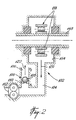
- Fig. 1 illustrates a known type of valve comprising a ball 12 which is displaceable along a vertical axis by fluid pressure to allow a fluid to flow from an inlet port 14 to an outlet passage 16 defined in a valve body 18.
- the valve body 18 defines an annular seat 20 on which the ball 12 sealingly rests when the pressure exerted on an upstream facing surface thereof is less than the weight of the ball 12 or than the sum of the downward forces exerted thereon. Under such conditions, the outlet passage 16 of the valve 10 is closed by the ball 12.
- reference numeral 12' when the fluid pressure on the upstream side of the ball 12 becomes greater than the downward forces exerted thereon, the latter is displaced upwardly against a plurality of inwardly bent tabs 22.
- the tabs 22 are uniformly distributed about the circumference of the upper end portion of the valve body 18 to allow fluid to flow through the outlet passage 16.
- the tabs 22 form an integral part of the valve body 18 and are flexible in order to permit the replacement of the ball 12.
- the valve 100 may be installed in a lubricating system 102 of a gas turbine engine of an aircraft for diverting, under certain operating conditions, a portion of the flow of a lubricating fluid passing through a main fluid line 104 into a secondary fluid line 106 mounted in parallel thereto.
- the valve 100 generally comprises a closure member, such as a ball 108, which can be displaced upwardly away from a valve seat 110 for allowing the lubricating fluid to flow through the secondary fluid line 106 when sufficient fluid pressure is exerted on a downstream facing surface of the ball 108.
- the lubricating system 102 comprises a pump 112 connected to the main fluid line 104 for drawing the lubricating fluid out of a bearing housing 114 containing bearings 116 which are disposed and configured to support a main rotating shaft 118 of the gas turbine engine.
- the pressure generated by the compressor (not shown) of the gas turbine engine is not sufficient to prevent the lubricating fluid supplied to the bearing housing 114 from flowing through the cabin ventilation system (not shown).
- the pump 112 must therefore be operated such as to create a vacuum in the bearing housing 114 thereby forcing the lubricating fluid to flow through the main fluid line 104 towards the pump 112, as indicated by arrow 120.
- the fluid pressure P 1 upstream of the valve 100 is less than the valve opening pressure, i.e. the sum of the weight of the ball 108 and the pressure P 2 on the downstream side thereof, and thus the ball 108 sealingly rests on the valve seat 110 to block fluid flow through the secondary fluid line 106.
- the fluid pressure P 1 upstream of the valve 100 becomes greater than the valve opening pressure and consequently the ball 108 is displaced away from the valve seat 110 to thus enable lubricating fluid to flow through the secondary fluid line 106, as indicated by arrow 122, and then through an accessory gear box (not shown) communicating therewith. Accordingly, the pump 112 will continue to draw the same quantity of fluid and the excess flow generated by the action of the compressor will pass through the secondary fluid line 106.
- the pressure P 1 and P 2 are in the order of 100psi and 40psi, respectively. It is the compressor which causes the pressure P 1 to be greater than the pressure P 2 .
- both the lubricating fluid drawn by the pump 112 and the lubricating fluid flowing through the secondary fluid line 106 are submitted to appropriate treatments and subsequently returned to a supply tank (not shown).
- the lubricating fluid consists of a mixture of air and oil and thus the air must be removed from the oil prior to returning the oil to the supply tank.
- the three-way valve 100 comprises a valve body 124 defining a primary flow path or fluid passage 126 for conducting a fluid from an inlet port 128 to a first outlet port 130 and a secondary fluid passage 132 communicating with the primary fluid passage 126 for directing a fluid from the inlet port 128 to a second outlet port (not shown).
- the primary and secondary fluid passages 126 and 132 each have a substantially cylindrical configuration.
- the valve seat 110 is integrally formed in the secondary fluid passage 132 of the valve body 124 and has an annular configuration to match the contour of the ball 108, thus fluid cannot pass between the ball 108 and the valve seat 110 when the ball 108 is in a closed position in order to block fluid flow through the secondary fluid passage 132 of the valve 100, as shown in dotted lines with reference to numeral 108'.
- the ball 108 is trapped inside a cavity 134 defined in the valve body 124 and will float therein.
- the cavity 134 includes an open end defining an entry area 136 which comprises a cylindrical portion 138 and a tapered portion 140 extending downwardly from the circumference of the cylindrical portion 138. As shown in Fig. 3, the entry area 136 is located outwardly of a flow path defined by the primary fluid passage 126 and the secondary fluid passage 132.
- the cavity 134 is dimensioned and configured such as to permit insertion and removal of the ball 108 from the valve 100.
- annular insert 142 is disposed therein for providing a seat against which the ball 108 may abut when displaced in an open position thereof by fluid pressure.
- a conventional retaining ring 144 is installed in an annular groove 146 defined in the cylindrical portion 138 of the entry area 136 of the cavity 134 to block the annular insert 142.
- the downward movements of the annular insert 142 are limited by the inner conical wall defining the tapered portion 140 of the entry area 136 of the cavity 134.
- the annular insert 142 may be made of any suitable material that is softer than the material from which the ball 108 is made but hard enough not to wear too rapidly. For instance, if both the ball 108 and the annular insert 142 are made of steel, the insert 142 would be constituted of a more malleable steel than that of the ball 108.
- the ball 108 has a diameter of 11/16 inch (1,75 cm) and the annular insert 142 has an inner diameter of 0.6 inch (1,52 cm), and outer diameter of 3 ⁇ 4 inch (1,9 cm) and a thickness of about 0,04 inch (0,1 cm).
- the ball 108 sealingly rests upon the valve seat 110 as long as the fluid pressure on the upstream side of the valve 100 is inferior to the opening pressure of the valve 100. Accordingly, under such conditions, the fluid only flows through the primary fluid passage 126 of the valve 100.
- the ball 108 When the value of the fluid pressure upstream of the valve 100 becomes greater than the valve opening pressure, the ball 108 is displaced upwardly against the annular insert 142 thereby allowing the fluid to flow through the secondary fluid passage 132 and the outlet opening 133 defined in the valve body 124.
- the annular insert 142 retains the ball 108 inside of the cavity 134 and acts as a spacer for preventing the ball 108 from directly contacting the valve body 124 when urged in the open position thereof by the fluid pressure.
- the annular insert 142 contributes to increase the life service of the valve 100, as it prevents the ball 108 from wearing by friction caused by contact the ball 108 and the inner walls of the valve body 124.
- annular insert 142 When the annular insert 142 is damaged due to use over a certain period of time, it can be readily replaced by a new similar annular insert.
- the above described arrangement is highly advantageous as it minimizes the wear of the valve body 124 and thus reduces the cost associated with the utilization of the above described type of valve.
- valve 100 is not restricted to the above described gas turbine engine application and that it may be employed in any other applications which necessitate the control of a fluid flow through a conduit.
Landscapes
- Engineering & Computer Science (AREA)
- General Engineering & Computer Science (AREA)
- Mechanical Engineering (AREA)
- Taps Or Cocks (AREA)
- Check Valves (AREA)
- Lift Valve (AREA)
Applications Claiming Priority (3)
| Application Number | Priority Date | Filing Date | Title |
|---|---|---|---|
| US88893 | 1998-06-02 | ||
| US09/088,893 US6035890A (en) | 1998-06-02 | 1998-06-02 | Retainer insert for a valve having a floating closure member |
| PCT/CA1999/000451 WO1999063253A1 (en) | 1998-06-02 | 1999-05-20 | Retainer insert for a valve having a floating closure member |
Publications (2)
| Publication Number | Publication Date |
|---|---|
| EP1082564A1 EP1082564A1 (en) | 2001-03-14 |
| EP1082564B1 true EP1082564B1 (en) | 2004-11-24 |
Family
ID=22214127
Family Applications (1)
| Application Number | Title | Priority Date | Filing Date |
|---|---|---|---|
| EP99920511A Expired - Lifetime EP1082564B1 (en) | 1998-06-02 | 1999-05-20 | Retainer insert for a valve having a floating closure member |
Country Status (7)
| Country | Link |
|---|---|
| US (1) | US6035890A (enExample) |
| EP (1) | EP1082564B1 (enExample) |
| JP (1) | JP2002517683A (enExample) |
| CA (1) | CA2333353C (enExample) |
| DE (1) | DE69922191T2 (enExample) |
| PL (1) | PL189457B1 (enExample) |
| WO (1) | WO1999063253A1 (enExample) |
Families Citing this family (6)
| Publication number | Priority date | Publication date | Assignee | Title |
|---|---|---|---|---|
| AU4449102A (en) * | 2001-06-11 | 2002-12-12 | C-Dax Systems Limited | Improvements in tanks |
| JP6473473B2 (ja) * | 2017-03-27 | 2019-02-20 | 本田技研工業株式会社 | 弁構造及びそれを用いた油圧回路 |
| DE102017219004A1 (de) | 2017-10-24 | 2019-04-25 | Brose Fahrzeugteile GmbH & Co. Kommanditgesellschaft, Würzburg | Elektromotorische Ölpumpe mit Rückschlagventil |
| US10767520B1 (en) | 2019-08-19 | 2020-09-08 | Caterpillar Inc. | Valve seat insert for long life natural gas lean burn engines |
| DE102020100590A1 (de) * | 2020-01-13 | 2021-07-15 | Schwäbische Hüttenwerke Automotive GmbH | Ventilanordnung, insbesondere Rückschlagventil mit eingepresstem Kugelhalter |
| US11549613B2 (en) * | 2020-10-06 | 2023-01-10 | Vianney Rabhi | Valve plate with free micro-balls |
Family Cites Families (11)
| Publication number | Priority date | Publication date | Assignee | Title |
|---|---|---|---|---|
| US2091058A (en) * | 1934-02-03 | 1937-08-24 | Charles N Hough Mfg Company | Ball valve |
| US3105516A (en) * | 1961-12-04 | 1963-10-01 | Ladish Co | Ball check valves |
| DE1941306A1 (de) * | 1969-08-14 | 1971-02-18 | Sandford Patent Trust | Umlenkventil |
| US3723996A (en) * | 1971-12-07 | 1973-04-03 | American Hospital Supply Corp | Cloth covered heart valve with protected cage legs |
| DE2556791A1 (de) * | 1975-12-17 | 1977-09-22 | Hahn Metallbau Gmbh | Ventil fuer einen druckbehaelter, insbesondere fuer eine treibflasche fuer ein feuerloeschgeraet |
| US4069840A (en) * | 1976-01-30 | 1978-01-24 | Brown Cicero C | Ball check valve |
| US4217846A (en) * | 1978-07-17 | 1980-08-19 | Wight Gary E | Boat bailing apparatus |
| US4282897A (en) * | 1979-05-29 | 1981-08-11 | The Perkin-Elmer Corporation | Valve assembly for pressurized fluid systems |
| BR8501845A (pt) * | 1984-04-25 | 1985-09-10 | Asca Equip Ltd | Capsula achatada com membrana para controle termico da saida de condensado |
| US4646783A (en) * | 1985-08-09 | 1987-03-03 | Alberto Bazan | Anti-stall ball-check valve |
| US5178184A (en) * | 1991-08-12 | 1993-01-12 | Skillman Milton M | Pump valve apparatus |
-
1998
- 1998-06-02 US US09/088,893 patent/US6035890A/en not_active Expired - Lifetime
-
1999
- 1999-05-20 PL PL99344363A patent/PL189457B1/pl not_active IP Right Cessation
- 1999-05-20 JP JP2000552423A patent/JP2002517683A/ja active Pending
- 1999-05-20 WO PCT/CA1999/000451 patent/WO1999063253A1/en not_active Ceased
- 1999-05-20 CA CA002333353A patent/CA2333353C/en not_active Expired - Lifetime
- 1999-05-20 DE DE69922191T patent/DE69922191T2/de not_active Expired - Fee Related
- 1999-05-20 EP EP99920511A patent/EP1082564B1/en not_active Expired - Lifetime
Also Published As
| Publication number | Publication date |
|---|---|
| PL344363A1 (en) | 2001-11-05 |
| PL189457B1 (pl) | 2005-08-31 |
| DE69922191T2 (de) | 2005-07-28 |
| JP2002517683A (ja) | 2002-06-18 |
| DE69922191D1 (de) | 2004-12-30 |
| US6035890A (en) | 2000-03-14 |
| EP1082564A1 (en) | 2001-03-14 |
| CA2333353A1 (en) | 1999-12-09 |
| WO1999063253A1 (en) | 1999-12-09 |
| CA2333353C (en) | 2006-06-06 |
Similar Documents
| Publication | Publication Date | Title |
|---|---|---|
| US7871364B2 (en) | Centrifuge rotor-detection oil-shutoff device | |
| US6343589B1 (en) | Fuel system with jet pump switching regulator | |
| US8210316B2 (en) | Oil scavenge system for a gas turbine engine | |
| US8348595B2 (en) | Sealing system between bearing and compressor housing | |
| US6505615B2 (en) | Device to deoil the crankcase ventilation gases of an internal combustion engine | |
| US4911196A (en) | Inline check valve | |
| US11679353B2 (en) | Separating device for separating a fluid from gas as well as separating element and coupling element for such a separating device | |
| EP0302264A1 (en) | Automobile coolant flow control | |
| EP1873359A2 (en) | Biased air film riding seal with reduced leakage in event of housing breach for shared engine lubrication accessory gearboxes | |
| JPH0658454A (ja) | ダイアフラム・サポートを備えたレギュレーター・バルブ | |
| EP1082564B1 (en) | Retainer insert for a valve having a floating closure member | |
| US20130105717A1 (en) | Media Control Valve | |
| JP2002525511A (ja) | 切換弁 | |
| WO1990001626A1 (en) | Shut off/pressure regulating valve for turbine engine | |
| US9038662B2 (en) | High pressure relief valve spring assembly | |
| EP1455084B1 (en) | Check valve for fuel pump | |
| CN108138709A (zh) | 燃料箱用通气控制阀 | |
| US9328835B2 (en) | High pressure relief valve piston | |
| EP1342503B1 (en) | A centrifuge assembly and a method of draining a centrifuge assembly | |
| US20180066589A1 (en) | High Pressure Relief Valve Nozzle | |
| US6079942A (en) | Pump seal flushing ring | |
| AU2015101051B4 (en) | Fluid flow manager | |
| CN113454327A (zh) | 用于燃料截止阀的限流装置 | |
| EP3715581A1 (en) | Fluid flow manager | |
| JPH1047500A (ja) | 加圧弁 |
Legal Events
| Date | Code | Title | Description |
|---|---|---|---|
| PUAI | Public reference made under article 153(3) epc to a published international application that has entered the european phase |
Free format text: ORIGINAL CODE: 0009012 |
|
| 17P | Request for examination filed |
Effective date: 20001130 |
|
| AK | Designated contracting states |
Kind code of ref document: A1 Designated state(s): DE FR GB IT SE |
|
| 17Q | First examination report despatched |
Effective date: 20030220 |
|
| GRAP | Despatch of communication of intention to grant a patent |
Free format text: ORIGINAL CODE: EPIDOSNIGR1 |
|
| GRAS | Grant fee paid |
Free format text: ORIGINAL CODE: EPIDOSNIGR3 |
|
| GRAA | (expected) grant |
Free format text: ORIGINAL CODE: 0009210 |
|
| AK | Designated contracting states |
Kind code of ref document: B1 Designated state(s): DE FR GB IT SE |
|
| PG25 | Lapsed in a contracting state [announced via postgrant information from national office to epo] |
Ref country code: IT Free format text: LAPSE BECAUSE OF FAILURE TO SUBMIT A TRANSLATION OF THE DESCRIPTION OR TO PAY THE FEE WITHIN THE PRESCRIBED TIME-LIMIT;WARNING: LAPSES OF ITALIAN PATENTS WITH EFFECTIVE DATE BEFORE 2007 MAY HAVE OCCURRED AT ANY TIME BEFORE 2007. THE CORRECT EFFECTIVE DATE MAY BE DIFFERENT FROM THE ONE RECORDED. Effective date: 20041124 |
|
| REG | Reference to a national code |
Ref country code: GB Ref legal event code: FG4D |
|
| REF | Corresponds to: |
Ref document number: 69922191 Country of ref document: DE Date of ref document: 20041230 Kind code of ref document: P |
|
| PG25 | Lapsed in a contracting state [announced via postgrant information from national office to epo] |
Ref country code: SE Free format text: LAPSE BECAUSE OF FAILURE TO SUBMIT A TRANSLATION OF THE DESCRIPTION OR TO PAY THE FEE WITHIN THE PRESCRIBED TIME-LIMIT Effective date: 20050224 |
|
| ET | Fr: translation filed | ||
| PLBE | No opposition filed within time limit |
Free format text: ORIGINAL CODE: 0009261 |
|
| STAA | Information on the status of an ep patent application or granted ep patent |
Free format text: STATUS: NO OPPOSITION FILED WITHIN TIME LIMIT |
|
| 26N | No opposition filed |
Effective date: 20050825 |
|
| PGFP | Annual fee paid to national office [announced via postgrant information from national office to epo] |
Ref country code: DE Payment date: 20080530 Year of fee payment: 10 |
|
| PG25 | Lapsed in a contracting state [announced via postgrant information from national office to epo] |
Ref country code: DE Free format text: LAPSE BECAUSE OF NON-PAYMENT OF DUE FEES Effective date: 20091201 |
|
| REG | Reference to a national code |
Ref country code: FR Ref legal event code: PLFP Year of fee payment: 18 |
|
| REG | Reference to a national code |
Ref country code: FR Ref legal event code: PLFP Year of fee payment: 19 |
|
| REG | Reference to a national code |
Ref country code: FR Ref legal event code: PLFP Year of fee payment: 20 |
|
| PGFP | Annual fee paid to national office [announced via postgrant information from national office to epo] |
Ref country code: FR Payment date: 20180423 Year of fee payment: 20 |
|
| PGFP | Annual fee paid to national office [announced via postgrant information from national office to epo] |
Ref country code: GB Payment date: 20180419 Year of fee payment: 20 |
|
| REG | Reference to a national code |
Ref country code: GB Ref legal event code: PE20 Expiry date: 20190519 |
|
| PG25 | Lapsed in a contracting state [announced via postgrant information from national office to epo] |
Ref country code: GB Free format text: LAPSE BECAUSE OF EXPIRATION OF PROTECTION Effective date: 20190519 |