EP1081883A2 - Système et procedé d'amplification et de surveillance d'amplificateurs - Google Patents
Système et procedé d'amplification et de surveillance d'amplificateurs Download PDFInfo
- Publication number
- EP1081883A2 EP1081883A2 EP20000307452 EP00307452A EP1081883A2 EP 1081883 A2 EP1081883 A2 EP 1081883A2 EP 20000307452 EP20000307452 EP 20000307452 EP 00307452 A EP00307452 A EP 00307452A EP 1081883 A2 EP1081883 A2 EP 1081883A2
- Authority
- EP
- European Patent Office
- Prior art keywords
- booster
- base station
- signal
- information
- reference signal
- Prior art date
- Legal status (The legal status is an assumption and is not a legal conclusion. Google has not performed a legal analysis and makes no representation as to the accuracy of the status listed.)
- Granted
Links
- 238000012544 monitoring process Methods 0.000 title claims description 182
- 238000000034 method Methods 0.000 title claims description 20
- 230000005540 biological transmission Effects 0.000 claims abstract description 98
- 230000004044 response Effects 0.000 claims abstract description 40
- 241000269799 Perca fluviatilis Species 0.000 claims abstract description 35
- 230000008859 change Effects 0.000 claims description 5
- 230000000694 effects Effects 0.000 abstract description 16
- 230000002411 adverse Effects 0.000 abstract description 4
- 230000014509 gene expression Effects 0.000 description 11
- 238000010586 diagram Methods 0.000 description 8
- 230000007257 malfunction Effects 0.000 description 5
- 230000002829 reductive effect Effects 0.000 description 5
- 238000011144 upstream manufacturing Methods 0.000 description 4
- 238000010295 mobile communication Methods 0.000 description 3
- 238000004891 communication Methods 0.000 description 2
- 230000003247 decreasing effect Effects 0.000 description 2
- 239000000284 extract Substances 0.000 description 2
- 238000005259 measurement Methods 0.000 description 2
- 238000012986 modification Methods 0.000 description 2
- 230000004048 modification Effects 0.000 description 2
- 230000002093 peripheral effect Effects 0.000 description 2
- 230000009467 reduction Effects 0.000 description 2
- 230000002159 abnormal effect Effects 0.000 description 1
- 239000012141 concentrate Substances 0.000 description 1
- 230000009931 harmful effect Effects 0.000 description 1
- 238000009434 installation Methods 0.000 description 1
- 230000000670 limiting effect Effects 0.000 description 1
- 230000036961 partial effect Effects 0.000 description 1
- 238000012545 processing Methods 0.000 description 1
- 239000013589 supplement Substances 0.000 description 1
- 238000012546 transfer Methods 0.000 description 1
Images


Classifications
-
- H—ELECTRICITY
- H04—ELECTRIC COMMUNICATION TECHNIQUE
- H04B—TRANSMISSION
- H04B7/00—Radio transmission systems, i.e. using radiation field
- H04B7/14—Relay systems
- H04B7/15—Active relay systems
- H04B7/155—Ground-based stations
- H04B7/15528—Control of operation parameters of a relay station to exploit the physical medium
- H04B7/15535—Control of relay amplifier gain
-
- H—ELECTRICITY
- H04—ELECTRIC COMMUNICATION TECHNIQUE
- H04W—WIRELESS COMMUNICATION NETWORKS
- H04W24/00—Supervisory, monitoring or testing arrangements
- H04W24/10—Scheduling measurement reports ; Arrangements for measurement reports
-
- H—ELECTRICITY
- H04—ELECTRIC COMMUNICATION TECHNIQUE
- H04B—TRANSMISSION
- H04B17/00—Monitoring; Testing
- H04B17/30—Monitoring; Testing of propagation channels
- H04B17/309—Measuring or estimating channel quality parameters
- H04B17/345—Interference values
-
- H—ELECTRICITY
- H04—ELECTRIC COMMUNICATION TECHNIQUE
- H04W—WIRELESS COMMUNICATION NETWORKS
- H04W52/00—Power management, e.g. TPC [Transmission Power Control], power saving or power classes
- H04W52/04—TPC
-
- H—ELECTRICITY
- H04—ELECTRIC COMMUNICATION TECHNIQUE
- H04W—WIRELESS COMMUNICATION NETWORKS
- H04W72/00—Local resource management
- H04W72/12—Wireless traffic scheduling
Definitions
- the present invention relates to a booster for receiving, amplifying and transmitting signals to be transferred between a base station and a mobile station, a monitoring equipment of the booster, a booster system, a control method of the booster and a monitoring method of the booster.
- the gain of a booster is adjusted at the installation of the booster before its operation.
- the gain of a booster is G b
- the noise figure of the booster is NF b
- its thermal noise is N kT
- the noise at a base station without the booster is N bs
- the propagation loss between the booster and base station is L
- N bs G b NF b N kT /L
- the booster When a new base station is installed near the booster, the booster is readjusted to make the effect of the booster on the new base station sufficiently small.
- a new base station installed in an area covered by the booster because of poor radio wave intensity in mobile communication can suffer from the noise or interference of the booster.
- CDMA Code Division Multiple Access
- the system performance of CDMA (Code Division Multiple Access) utilizing the same frequency depends greatly on the interference.
- the gain of the booster must be readjusted manually at the spot every time a new base station is installed near the booster.
- the area under the base station is greater.
- the traffic under the booster must be limited by reducing the gain of the booster, for example.
- the booster is a device for receiving and amplifying radio waves, and transmitting them into space, its failure or malfunction will have a large effect on channel quality. Accordingly, it is preferable to monitor an increasing number of items. In addition, it is desirable to monitor not only amplifiers, but also failures of operation circuits and the like.
- the mobile station when the gain of an uplink signal is much smaller than the gain of a downlink signal, the mobile station increases its transmission power to maintain prescribed quality. Accordingly, it is difficult for the base station to detect a failure of the booster.
- Another object of the present invention is to adjust the balance between the traffic under the booster and the traffic under the base station by controlling the gain of the booster.
- Still another object of the present invention is to carry out suitable monitoring of a booster by transmitting information about the booster (information about parameters for setting the gain of the booster, information about the condition of the booster and the like) to a monitoring equipment so that the monitoring equipment monitors the booster using these information items.
- the booster amplifies the radio waves (uplink signal) transmitted from the mobile station, and that the propagation loss between base station A and the booster is L 1 [dB]. If the expression N o >> N b - L 1 is satisfied, where N o [dBm] is the noise power at the base station A, and N b [dBm] is the noise power of the amplified uplink signal at the booster, it can be said that the N b has little effect on the base station A. In other words, it can be said that the booster noise has little effect on the base station A if the following expressions are satisfied.
- G b is the gain of the booster
- NF b is the noise figure of the booster
- NF o is the noise figure of the base station A.
- the gain of the booster G b should be adjusted to satisfy the following expressions. N b ⁇ L 2 + N o G b ⁇ L 2 + NF o - NF b
- the interference quantity in the base station is I o
- the interference quantity of an uplink signal input in the booster is I b
- the interference quantity in the base station from the uplink signal which is amplified by the booster and transmitted to the base station is I b '
- the interference quantity I o in the base station is large and approximately satisfies the expression above, it can be estimated that the traffic under the booster is heavy, bearing severely upon the traffic under the base station. If the gain of the booster is reduced in such a case, the uplink communication of the CDMA tries to maintain the received level of the base station at a fixed level by carrying out transmission power control. Thus, the reduction in the booster gain little affects the interference quantity and traffic at an initial stage.
- the interference quantity I b ' from the booster to the base station gradually reduces, with the reduction in the received power of the downlink signal, thereby reducing the area under the booster.
- the decreasing interference quantity in the base station can increase the traffic under the base station.
- the received level and noise power density of the booster increase with the traffic under the booster. Varying the gain of the booster with the increase can change the area, thereby limiting the traffic under the booster.
- a booster for receiving, amplifying and transmitting a signal to be transferred between a base station and a mobile station comprising:
- the booster may further comprise:
- the booster may further comprise:
- the booster may further comprise:
- a booster for receiving, amplifying and transmitting a signal to be transferred between a base station and a mobile station comprising:
- the booster may further comprise:
- the reference signal may include information about the interference quantity in the base station, and the interference quantity information receiver may receive the information about the interference quantity in the base station by receiving the reference signal.
- the reference signal may include information about transmission power of the reference signal at the base station, and the transmission power information receiver may receive the information about the transmission power of the reference signal at the base station by receiving the reference signal.
- a booster for receiving, amplifying and transmitting a signal to be transferred between a base station and a mobile station comprising:
- the booster may further comprise:
- a booster for receiving, amplifying and transmitting a signal to be transferred between a base station and a mobile station comprising:
- the booster may further comprise:
- the reference signal may include the information about the interference quantity in the base station, and the interference quantity information receiver may receive the information about the interference quantity in the base station by receiving the reference signal.
- the booster may further comprise:
- the reference signal may include the information about the transmission power of the reference signal at the base station, and the transmission power information receiver may receive the information about transmission power of the reference signal at the base station by receiving the reference signal.
- the booster may further comprise:
- the information transmitter may transmit information about the gain of the uplink signal to the monitoring equipment for monitoring the booster.
- the booster may further comprise a downlink signal amplifier for amplifying a downlink signal from the base station to the mobile station.
- the information transmitter may transmit the information about the gain of the downlink signal to the monitoring equipment for monitoring the booster.
- the downlink signal amplifier may be able to change a time constant for adjusting the gain of the downlink signal.
- the booster may further comprise:
- the booster controller may control, when the control signal is a signal for controlling the gain of the uplink signal and/or the gain of the downlink signal, the gain of the uplink signal and/or the gain of the downlink signal in accordance with the control signal.
- the reference signal may be a perch signal.
- the uplink signal amplifier may be able to vary a time constant for adjusting the gain of the uplink signal.
- the downlink signal amplifier may be able to vary a time constant for adjusting the gain of the downlink signal.
- a booster for receiving, amplifying and transmitting a signal to be transferred between a mobile station and a base station, wherein the booster can vary a time constant for adjusting an gain of the signal.
- a monitoring equipment for monitoring a booster for receiving, amplifying and transmitting a signal to be transferred between a mobile station and a base station comprising:
- the monitoring equipment may further comprise:
- a monitoring equipment for monitoring a booster for receiving, amplifying and transmitting a signal to be transferred between a mobile station and a base station comprising:
- the reference signal may include the information about the interference quantity in the base station
- the third information receiver may receive the information about the interference quantity in the base station by receiving the reference signal.
- the third information receiver may receive the information about the interference quantity in the base station, which information is transmitted from the booster.
- the third information receiver may receive, at the base station, the information about the interference quantity in the base station, and the monitoring unit may acquire the information about the interference quantity in the base station from the third information receiver via a telephone line.
- the reference signal may include information about transmission power of the reference signal at the base station, and the second information receiver may receive the information about the transmission power of the reference signal at the base station by receiving the reference signal.
- the second information receiver may receive the information about the transmission power of the reference signal at the base station, which information is transmitted from the booster.
- the first information receiver may receive, at the base station, information about the received power at the booster of the reference signal transmitted from the base station and the noise power of the amplified uplink signal at the booster;
- the first information receiver may receive information about the gain of the uplink signal and/or about the gain of the downlink signal; and the monitoring unit may monitor the booster in response to the gain of the uplink signal and/or the gain of the downlink signal, as well.
- the monitoring equipment may further comprise:
- the reference signal may be a perch signal.
- a booster system including a booster for receiving, amplifying and transmitting a signal to be transferred between a base station and a mobile station, and a monitoring equipment for monitoring the booster, wherein
- a booster system including a booster for receiving, amplifying and transmitting a signal to be transferred between a base station and a mobile station, and a monitoring equipment for monitoring the booster, wherein
- a monitoring method of monitoring a booster for receiving, amplifying and transmitting a signal to be transferred between a mobile station and a base station comprising the steps of:
- a monitoring method of monitoring a booster for receiving, amplifying and transmitting a signal to be transferred between a mobile station and a base station comprising:
- the foregoing configuration makes it possible to reduce the harmful effect of the booster noise on the base station by controlling the gain of the booster.
- the gain control of the booster makes it possible to control the balance between the traffic under the booster and the traffic under the base station.
- the monitoring equipment can carry out its monitoring appropriately using the information about the booster, which is transmitted to it, such as the information about parameters for setting the gain of the booster, and information about the condition of the booster.
- Fig. 1 is a block diagram showing a configuration of a booster of a first embodiment in accordance with the present invention.
- a booster 100 of the present embodiment comprises power dividers 104 and 106, variable attenuators 108 and 110, an operation circuit 112, amplifiers 114 and 116, a receiver 118, a transmitter 120, a combiner 122, a condition-monitoring circuit 124, duplexers 126 and 128, antennas 130 and 132, a noise measuring unit 140 and an interference measuring unit 150.
- the noise measuring unit 140 includes a bandpass filter (BPF) 142 and a detector 144
- the interference measuring unit 150 includes a bandpass filter 152 and a detector 154.
- the booster 100 receives, amplifies and transmits downlink signals from base stations 180, 182 and the like to a mobile station 190 and the like, and uplink signals from the mobile station 190 and the like to the base stations 180, 182 and the like. More specifically, it receives the signals transmitted from the base stations 180, 182 and the like, amplifies the received signals, and transmits the amplified signals to the mobile station 190 and the like. On the other hand, it receives the signals transmitted from the mobile station 190 and the like, amplifies the received signals, and transmits the amplified signals to the base stations 180, 182 and the like.
- the signals (downlink signals) transmitted from the base stations 180, 182 and the like are supplied to the variable attenuator 108 via the antenna 130, duplexer 126 and power divider 104 and then to the amplifier 114 with being amplified through the variable attenuator 108 and amplifier 114 by a particular gain, and are transmitted to the mobile station 190 and the like via the duplexer 128 and antenna 132.
- the signals (uplink signals) transmitted from the mobile station 190 and the like are supplied to the amplifier 116 via the antenna 132, duplexer 128 and combiner 122, and then to the variable attenuator 110 with being amplified through the amplifier 116 and variable attenuator 110 by a particular gain, and are transmitted to the base stations 180, 182 and the like via the power divider 106, duplexer 126 and antenna 130.
- the receiver 118 has the same configuration as the receiver of the mobile station
- the transmitter 120 has the same configuration as the transmitter of the mobile station so that they are inexpensive.
- the booster 100 controls the gain of the uplink signals and the gain of the downlink signals in accordance with the foregoing expression (4) to reduce the effect of the noise of the booster 100 on the base stations 180, 182 and the like. It is assumed here that the noise figure NF o of the base station is known in advance.
- each base station In the mobile communication, each base station normally transmits a perch signal continuously which is used for searching for a visited cell.
- the receiver 118 extracts from the perch signal the information about the transmission power of the perch signal at the base station (and the information about the interference quantity of the amplified uplink signal in the base station). Furthermore, the receiver 118 measures the received power of the perch signal received. It is also possible for the booster to directly receive the information about the transmission power of the perch signal at the base station without receiving the perch signal.
- the present embodiment uses the perch signal as a reference signal for measuring the propagation loss between the booster and base station or the like, it can also use a signal other than the perch signal as the reference signal.
- the booster measures the noise power N b of the amplified uplink signal at the booster using the noise measuring unit 140.
- the noise measurement it is enough to measure power density.
- the present embodiment measures the noise power N b using the narrow-band bandpass filter 142 with a frequency immediately next to the operating band, and the detector 144. Once the noise power N b has been measured, the noise figure of the booster NF b can be obtained.
- the effect of the noise of the booster 100 on the base stations 180, 182 and the like can be reduced by automatically controlling the gain G b of the booster 100 using the noise figure NF o of the base station thus obtained, the propagation loss L 1 between the base station and the booster, the noise figure NF b of the booster and expression (4).
- the control of the gain of the uplink signals is carried out by transferring a gain setting signal from the operation circuit 112 to the amplifier 116 and variable attenuator 110 to control them.
- the control of the gain of the downlink signals is carried out by transferring a gain setting signal from the operation circuit 112 to the amplifier 114 and variable attenuator 108 to control them.
- the gain of the uplink signals may differ from the gain of the downlink signals.
- data volumes usually differ between downlink channels and uplink channels, and generally, the downlink channels have a greater volume. In such a case, it is possible to operate the booster at minimum power required by providing a difference between the gain of the uplink signals and the gain of the downlink signals.
- the amplifier 116 and variable attenuator 110 can control the time constant for the variation.
- the amplifier 114 and variable attenuator 108 can control the time constant for the variation. It is preferable that the time constant for varying the gain of the uplink signals and that for varying the gain of the downlink signals be increased in order to prevent the effect on the transmission power control of the base station or mobile station.
- the booster 100 always scans the perch signals of peripheral base stations, and the receiver 118 searches for a perch signal with the highest received level. For example, when a second base station is newly installed near the booster 100, and if the propagation loss L 2 between the second base station and the booster 100 satisfies the relationship L 1 > L 2 , where L 1 is the propagation loss between the first base station and the booster 100, the gain G b of the booster 100 is controlled to satisfy the foregoing expression (6) (corresponding to expression (4)). Thus, when the new base station is installed near the booster 100, the gain of the booster is reduced in response to the new base station to weaken the effect of the noise and interference quantity on the base station.
- the gain of the booster can be increased within the limit satisfying the relationship of the foregoing expression (4). Even if the base station exchanging signals with the booster becomes inoperable, the booster can continue the mobile communication service by searching for the perch signals from the peripheral base stations, and by amplifying radio waves, if the booster can receive the radio waves from at least one of the base stations.
- the present embodiment extracts from the perch signal the information about the interference quantity I o in the base station, the information can also be directly received from the base station without receiving the perch signal.
- the propagation loss L between the base station and the booster can be obtained by the method described above.
- the interference quantity G b + I b of the amplified uplink signals in the booster is measured by the interference measuring unit 150.
- the interference quantity measurement it is enough to measure the power density.
- the interference quantity G b + I b is measured using the narrow-band bandpass filter 152 passing signals within the band, and the detector 154. Once the G b + I b and L have been obtained, the I b ' can be obtained.
- the balance between the traffic under the booster and the traffic under the base station can be adjusted by controlling the gain G b of the booster 100 in response to the interference quantity I o in the base station and the interference quantity I b ' to the base station by the amplified uplink signals.
- the booster 100 transmits to the monitoring equipment the information about the parameters for setting the gain of the booster 100, the information on the condition of the booster 100 and the like. On the other hand, receiving a control signal from the monitoring equipment, the booster 100 follows the control signal.
- the booster 100 also transmits to the monitoring equipment the information about the parameters of setting the gain (the transmission power of the perch signal at each base station, the received power of the perch signal at the booster, the noise power of the amplified uplink signal at the booster, the interference quantity of the amplified uplink signal in the booster and the interference quantity in the base station), the booster condition and the gain (the gain of the uplink signals and the gain of the downlink signals).
- the gain the transmission power of the perch signal at each base station, the received power of the perch signal at the booster, the noise power of the amplified uplink signal at the booster, the interference quantity of the amplified uplink signal in the booster and the interference quantity in the base station
- the booster condition and the gain the gain of the uplink signals and the gain of the downlink signals.
- the information about the conditions of the booster is acquired by the condition-monitoring circuit 124, and is transmitted to the transmitter 120.
- the information about the conditions of the booster includes information about the power supply of the booster 100, information about the power supply of the amplifiers 114 and 116 and the like.
- the monitoring equipment can detect from them the failure or malfunction of the booster 100 or the possibility thereof. In addition, it can control the booster 100 by sending the control signal to the booster 100.
- the monitoring equipment carries out processing similar to that of the operation circuit 112 in the booster 100 using the parameters for setting the gain transmitted from the booster, thereby obtaining the gain. If the obtained gain disagrees with the gain transmitted from the booster, a failure of the operation circuit 112, amplifiers 114 and 116 or the like can take place.
- variable attenuators 108 and 110 and the amplifiers 114 and 116 fall into a failure, the balance between the uplink and down link is extremely disturbed.
- the gain of the uplink signals is greater than the gain of the downlink signals, the transmission power of the mobile stations communicating under the control of the booster 100 usually increases, which in turn increases the interference quantity. Since the monitoring equipment receives the information about the interference quantity of the amplified uplink signals to the booster, it can distinguish between an increase in the interference quantity due to a normal increase in the traffic and an increase in the interference quantity due to a failure.
- the booster 100 when it receives the control signal from the monitoring equipment, the booster 100 follows the control signal.
- the control signal can include, for example, a signal for controlling the gain, a signal for resetting the booster 100, and a signal for turning off the power supply to the booster 100.
- the operation circuit 112 controls the gain of the uplink signals and/or the gain of the downlink signals in response to the control signal.
- the monitoring equipment can achieve appropriate monitoring of the booster.
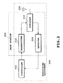
- Fig. 2 is a block diagram showing a configuration of the monitoring equipment of the booster of a second embodiment in accordance with the present invention.
- the monitoring equipment 200 of the present embodiment comprises a controller 202, a transmitter 212, a receiver 214, a duplexer 218 and an antenna 220.
- the transmitter 212, receiver 214, duplexer 218 and antenna 220 are the same as those of the base station 210 so that the base station 210 also carries out transmission and reception using the transmitter 212 and receiver 214.
- the receiver 214 and transmitter 212 have the same configurations as the receiver and transmitter of the mobile station, both of which are inexpensive.
- the controller 202 receives information about parameters for setting the gain of the booster, information about the conditions of the booster and the like, via the antenna 220, duplexer 218 and receiver 214, and monitors the booster using these items of information. More specifically, it detects a failure or malfunction of the booster 100, or their possibility from the information. In addition, it sends a control signal to the booster via the transmitter 212, duplexer 218 and antenna 220 to control the booster as needed.
- the various information items needed for monitoring do not require any extra receiver because they are received by the base station as an ordinary traffic channel.
- the monitoring equipment 200 can receive various information items, which enables appropriate monitoring of the booster.
- the monitoring equipment 200 of the present embodiment can be combined with the booster 100 of the first embodiment to configure a booster system.
- the booster 100 transmits to the monitoring equipment 200 the information about parameters for setting gain (such as the transmission power of the perch signal at each base station, received power of the perch signal at the booster, noise power of the amplified uplink signal at the booster, interference quantity of the amplified uplink signal in the booster and interference quantity in the base station), about the booster conditions, and about the gain (the gain of the uplink signals and the gain of the downlink signals).
- gain such as the transmission power of the perch signal at each base station, received power of the perch signal at the booster, noise power of the amplified uplink signal at the booster, interference quantity of the amplified uplink signal in the booster and interference quantity in the base station
- the monitoring equipment 200 monitors the booster on the basis of these information items.
- the booster transmits the information about the transmission power of the perch signal at the base station and the information about the interference quantity in the base station, because they can be directly transmitted from the base station to the controller of the monitoring equipment without passing through the booster.
- Fig. 3 is a block diagram showing a configuration of a booster monitoring equipment of a third embodiment in accordance with the present invention.
- the monitoring equipment 300 comprises a controller 302, a transmitter 312, receivers 304 and 314, a power divider 316, a duplexer 318, and an antenna 320.
- the present embodiment shares the transmitter 312, receiver 314, power divider 316, duplexer 318 and antenna 320 with the base station 310.
- the monitoring equipment 300 can receive by the receiver 304 a signal sent from the base station via the power divider 316, and transfer it to the controller 302.
- the monitoring equipment 300 can acquire the above-mentioned information about the transmission power of the perch signal at the base station and the information about the interference quantity in the base station without having the booster transmit them. If the perch signal includes these information items, the receiver 304 can collect them by receiving the perch signal via the power divider 316.
- the monitoring equipment 300 according to the present embodiment can receive the information items for implementing appropriate monitoring of the booster.
- the monitoring equipment 300 according to the present embodiment has a configuration more complicated than that of the monitoring equipment 200 according to the second embodiment because of the receiver 304, it can collect the information about the transmission power of the perch signal at the base station and the information about the interference quantity in the base station without transmitting them from the booster.
- the controller of the monitoring equipment can be installed at a location apart from the base station.
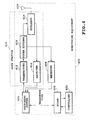
- Fig. 4 is a block diagram showing a configuration of a booster monitoring equipment of a fourth embodiment in accordance with the present invention.
- the monitoring equipment 400 comprises a controller 402, a switching system 406, a modem 408, a transmitter 412, receivers 404 and 414, a power divider 416, a duplexer 418 and an antenna 420.
- the present embodiment shares the transmitter 412, receiver 414, power divider 416, duplexer 418 and antenna 420 with the base station 410.
- the base station 410 receives the information from the booster, and transmits the information to the controller 402 by telephone line.
- the present embodiment has the base station receive information from the booster by radio, bringing about a partial solution for the cost.
- the booster usually carries out telephone conversations with the base station that sends the perch signal bringing about the maximum received power.
- the upstream base station of the booster is changed to the new base station. Therefore, when the booster monitoring equipment is installed at the same location as a particular base station, the change of the upstream base station of the booster will bring about a change of the situation: the booster continues to communicate with the monitoring equipment of the primary upstream base station; or a new monitoring equipment must be installed in the new upstream base station of the booster.
- the monitoring equipment 400 according to the present embodiment can also receive the various items of information required for the monitoring, enabling appropriate monitoring of the booster.
- the monitoring equipment 400 according to the present embodiment introduces the remote control via the telephone lines to the monitoring equipment 300 according to the third embodiment
- the monitoring equipment 200 according to the second embodiment can also introduce the remote control using the telephone lines.
- the present invention makes it possible to reduce the adverse effect of the booster noise on the base station by controlling the gain of the booster.
- it can adjust the balance between the traffic under the booster and the traffic under the base station by controlling the gain of the booster.
- transmitting to the monitoring equipment the information for monitoring the booster (the information about parameters for setting the gain of the booster, information about the condition of the booster and the like) enables the monitoring equipment to carry out appropriate monitoring of the booster using these information items.
Landscapes
- Engineering & Computer Science (AREA)
- Computer Networks & Wireless Communication (AREA)
- Signal Processing (AREA)
- Quality & Reliability (AREA)
- Physics & Mathematics (AREA)
- Electromagnetism (AREA)
- Mobile Radio Communication Systems (AREA)
- Monitoring And Testing Of Transmission In General (AREA)
- Radio Relay Systems (AREA)
Priority Applications (4)
| Application Number | Priority Date | Filing Date | Title |
|---|---|---|---|
| EP20090172527 EP2136491B1 (fr) | 1999-08-31 | 2000-08-30 | Système et procedé d'amplification et de surveillance d'amplificateurs |
| EP20080020937 EP2037599B1 (fr) | 1999-08-31 | 2000-08-30 | Suralimenteur, surveillance, appareil, système de suralimenteur, procédé de commande et procédé de surveillance |
| EP20080020938 EP2086128A1 (fr) | 1999-08-31 | 2000-08-30 | Suralimenteur, surveillance, appareil, système de suralimenteur, procédé de commande et procédé de surveillance |
| EP20040077859 EP1511193B1 (fr) | 1999-08-31 | 2000-08-30 | Sytème et procedé d'amplification et de surveillance d'amplificateurs |
Applications Claiming Priority (2)
| Application Number | Priority Date | Filing Date | Title |
|---|---|---|---|
| JP24650199A JP3782616B2 (ja) | 1999-08-31 | 1999-08-31 | ブースター、監視装置、ブースター・システム、制御方法および監視方法 |
| JP24650199 | 1999-08-31 |
Related Child Applications (8)
| Application Number | Title | Priority Date | Filing Date |
|---|---|---|---|
| EP20080020938 Division EP2086128A1 (fr) | 1999-08-31 | 2000-08-30 | Suralimenteur, surveillance, appareil, système de suralimenteur, procédé de commande et procédé de surveillance |
| EP20080020937 Division EP2037599B1 (fr) | 1999-08-31 | 2000-08-30 | Suralimenteur, surveillance, appareil, système de suralimenteur, procédé de commande et procédé de surveillance |
| EP20090172527 Division EP2136491B1 (fr) | 1999-08-31 | 2000-08-30 | Système et procedé d'amplification et de surveillance d'amplificateurs |
| EP20040077859 Division EP1511193B1 (fr) | 1999-08-31 | 2000-08-30 | Sytème et procedé d'amplification et de surveillance d'amplificateurs |
| EP04077859.9 Division-Into | 2004-10-15 | ||
| EP08020938.0 Division-Into | 2008-12-03 | ||
| EP08020937.2 Division-Into | 2008-12-03 | ||
| EP09172527.5 Division-Into | 2009-10-08 |
Publications (3)
| Publication Number | Publication Date |
|---|---|
| EP1081883A2 true EP1081883A2 (fr) | 2001-03-07 |
| EP1081883A3 EP1081883A3 (fr) | 2003-09-24 |
| EP1081883B1 EP1081883B1 (fr) | 2010-05-19 |
Family
ID=17149346
Family Applications (5)
| Application Number | Title | Priority Date | Filing Date |
|---|---|---|---|
| EP20090172527 Expired - Lifetime EP2136491B1 (fr) | 1999-08-31 | 2000-08-30 | Système et procedé d'amplification et de surveillance d'amplificateurs |
| EP20080020937 Expired - Lifetime EP2037599B1 (fr) | 1999-08-31 | 2000-08-30 | Suralimenteur, surveillance, appareil, système de suralimenteur, procédé de commande et procédé de surveillance |
| EP20040077859 Expired - Lifetime EP1511193B1 (fr) | 1999-08-31 | 2000-08-30 | Sytème et procedé d'amplification et de surveillance d'amplificateurs |
| EP20080020938 Withdrawn EP2086128A1 (fr) | 1999-08-31 | 2000-08-30 | Suralimenteur, surveillance, appareil, système de suralimenteur, procédé de commande et procédé de surveillance |
| EP20000307452 Expired - Lifetime EP1081883B1 (fr) | 1999-08-31 | 2000-08-30 | Système et procedé d'amplification et de surveillance d'amplificateurs |
Family Applications Before (4)
| Application Number | Title | Priority Date | Filing Date |
|---|---|---|---|
| EP20090172527 Expired - Lifetime EP2136491B1 (fr) | 1999-08-31 | 2000-08-30 | Système et procedé d'amplification et de surveillance d'amplificateurs |
| EP20080020937 Expired - Lifetime EP2037599B1 (fr) | 1999-08-31 | 2000-08-30 | Suralimenteur, surveillance, appareil, système de suralimenteur, procédé de commande et procédé de surveillance |
| EP20040077859 Expired - Lifetime EP1511193B1 (fr) | 1999-08-31 | 2000-08-30 | Sytème et procedé d'amplification et de surveillance d'amplificateurs |
| EP20080020938 Withdrawn EP2086128A1 (fr) | 1999-08-31 | 2000-08-30 | Suralimenteur, surveillance, appareil, système de suralimenteur, procédé de commande et procédé de surveillance |
Country Status (7)
| Country | Link |
|---|---|
| US (1) | US6690915B1 (fr) |
| EP (5) | EP2136491B1 (fr) |
| JP (1) | JP3782616B2 (fr) |
| KR (1) | KR100353413B1 (fr) |
| CN (1) | CN1272921C (fr) |
| AU (1) | AU770706B2 (fr) |
| DE (3) | DE60045753D1 (fr) |
Cited By (6)
| Publication number | Priority date | Publication date | Assignee | Title |
|---|---|---|---|---|
| WO2013040589A1 (fr) | 2011-09-15 | 2013-03-21 | Andrew Wireless Systems Gmbh | Sous-système de configuration pour systèmes de télécommunications |
| EP2428079A4 (fr) * | 2009-05-04 | 2017-03-01 | Telefonaktiebolaget LM Ericsson (publ) | Détermination du gain d'un répéteur en fonction d'une interférence |
| US9735843B2 (en) | 2011-07-11 | 2017-08-15 | Commscope Technologies Llc | Base station router for distributed antenna systems |
| US9894623B2 (en) | 2012-09-14 | 2018-02-13 | Andrew Wireless Systems Gmbh | Uplink path integrity detection in distributed antenna systems |
| US9913147B2 (en) | 2012-10-05 | 2018-03-06 | Andrew Wireless Systems Gmbh | Capacity optimization sub-system for distributed antenna system |
| US11412395B2 (en) | 2011-09-16 | 2022-08-09 | Andrew Wireless Systems Gmbh | Integrated intermodulation detection sub-system for telecommunications systems |
Families Citing this family (51)
| Publication number | Priority date | Publication date | Assignee | Title |
|---|---|---|---|---|
| CA2323881A1 (fr) * | 2000-10-18 | 2002-04-18 | Dps Wireless Inc. | Repeteur personnel adaptatif |
| JP2002245962A (ja) * | 2000-12-12 | 2002-08-30 | Jeol Ltd | エレクトロスプレー・イオン源 |
| US7263143B1 (en) * | 2001-05-07 | 2007-08-28 | Adaptix, Inc. | System and method for statistically directing automatic gain control |
| JP4489997B2 (ja) * | 2001-06-13 | 2010-06-23 | 株式会社日立国際電気 | 中継増幅器 |
| US6892080B2 (en) * | 2001-11-27 | 2005-05-10 | Arrista Technologies, Inc. | Booster amplifier for cellular telephone cradles |
| US20030185289A1 (en) * | 2001-12-07 | 2003-10-02 | Koninklijke Philips Electronics N.V. | Cordless modem for portable computers |
| US7050758B2 (en) * | 2002-02-28 | 2006-05-23 | Nortel Networks Limited | Self-configuring repeater system and method |
| US7024231B2 (en) * | 2002-10-28 | 2006-04-04 | Allen Cohen | Booster system in a cellular phone base station |
| AU2003293436A1 (en) * | 2002-12-05 | 2004-06-30 | Qualcomm, Incorporated | System and method for setting the reverse link gain of repeaters in wireless communication systems |
| CN1225849C (zh) * | 2003-07-18 | 2005-11-02 | 大唐移动通信设备有限公司 | 一种对无线信号进行双向同步转发的方法及装置 |
| WO2005034554A1 (fr) * | 2003-10-02 | 2005-04-14 | Fujitsu Limited | Repeteur |
| US7480485B1 (en) * | 2004-01-07 | 2009-01-20 | Sprint Spectrum L.P. | Radio frequency repeater with automated block/channel selection |
| US7299005B1 (en) | 2004-01-07 | 2007-11-20 | Sprint Spectrum L.P. | Radio frequency repeater with automated block/channel selection |
| US7221967B2 (en) * | 2004-09-14 | 2007-05-22 | Wilson Electronics, Inc. | Enhanced gain selected cell phone booster system |
| US20060058071A1 (en) * | 2004-09-14 | 2006-03-16 | Buren Alan V | Gain selected cell phone booster |
| EP1804397A4 (fr) | 2004-10-20 | 2012-03-14 | Panasonic Corp | Booster |
| US7418032B2 (en) * | 2005-03-15 | 2008-08-26 | International Business Machines Corporation | Altering power consumption in communication links based on measured noise |
| US7447490B2 (en) | 2005-05-18 | 2008-11-04 | Nvidia Corporation | In-situ gain calibration of radio frequency devices using thermal noise |
| EP2144467B1 (fr) * | 2005-06-17 | 2011-11-23 | Fujitsu Limited | Systèmes et procédés pour la commande de puissance dans un système de communication à bonds multiples |
| EP2144472A3 (fr) * | 2005-06-17 | 2011-03-16 | Fujitsu Limited | Procédé pour l'allocation de bande dans un système de communication à bonds multiples |
| US7848758B1 (en) | 2005-09-27 | 2010-12-07 | Sprint Spectrum L.P. | Dynamic allocation of carrier frequencies in wireless wide area networks |
| CN101300751A (zh) * | 2005-10-31 | 2008-11-05 | 艾利森电话股份有限公司 | 用于在无线通信系统中中继信号的方法和设备 |
| US8537761B1 (en) * | 2005-12-28 | 2013-09-17 | At&T Intellectual Property Ii, L.P. | Incorporation of mesh base stations in a wireless system |
| US7865159B2 (en) * | 2006-01-27 | 2011-01-04 | Qualcomm Incorporated | Repeater rise-over-thermal (RoT) value calibration |
| JP4847785B2 (ja) * | 2006-05-01 | 2011-12-28 | 株式会社エヌ・ティ・ティ・ドコモ | 無線中継増幅システム、無線中継方法 |
| US7623866B1 (en) | 2006-07-10 | 2009-11-24 | Sprint Spectrum L.P. | Automatic generation of neighbor lists in a wireless network |
| JP5016065B2 (ja) * | 2007-03-01 | 2012-09-05 | トムソン ライセンシング | マルチホップ無線ネットワークにおいてアクセス・ポイント又は中継ノードを選択する方法及び装置 |
| KR100893010B1 (ko) | 2007-05-21 | 2009-04-10 | 주식회사 케이티프리텔 | 감쇄 장치를 구비한 중계기의 가변 감쇄 방법 및 그 원격관리 시스템 |
| US8473018B2 (en) * | 2007-05-22 | 2013-06-25 | Wilson Electronics, Llc | Mobile device cradle having an integrated antenna or amplifier |
| JP5178414B2 (ja) * | 2007-09-26 | 2013-04-10 | 株式会社日立国際電気 | 無線中継増幅装置 |
| JP4776637B2 (ja) * | 2008-01-09 | 2011-09-21 | 三菱電機株式会社 | 通信システム |
| JP5107069B2 (ja) * | 2008-01-25 | 2012-12-26 | 株式会社エヌ・ティ・ティ・ドコモ | 移動通信システムで使用される基地局装置及び方法 |
| JP2010130439A (ja) * | 2008-11-28 | 2010-06-10 | Sumitomo Electric Ind Ltd | 無線中継装置 |
| US8498241B1 (en) | 2009-03-10 | 2013-07-30 | Sprint Spectrum L.P. | Use of macro-network channel-list messages for selection of carriers for low-cost internet base-station frequency-hopping pilot beacons |
| US8325648B1 (en) | 2009-04-29 | 2012-12-04 | Sprint Spectrum L.P. | Methods and systems for assigning a wireless communication device to a carrier frequency |
| US8320313B1 (en) | 2009-06-19 | 2012-11-27 | Sprint Spectrum L.P. | Method and system for carrier frequency management based on slot contention |
| US9107148B1 (en) | 2009-11-30 | 2015-08-11 | Sprint Spectrum L.P. | Use of pre-handoff macro-carrier data for prioritization of carriers in femtocell frequency-hopping pilot beacons |
| US8346160B2 (en) * | 2010-05-12 | 2013-01-01 | Andrew Llc | System and method for detecting and measuring uplink traffic in signal repeating systems |
| CN102448103B (zh) * | 2010-10-11 | 2014-07-02 | 中兴通讯股份有限公司 | 一种分布式网络无线射频指标智能实时改进的方法及装置 |
| US8798013B1 (en) | 2011-03-25 | 2014-08-05 | Sprint Spectrum L.P. | Method and system for management of data transmission in timeslots |
| CN103416088A (zh) * | 2011-04-28 | 2013-11-27 | 富士通株式会社 | 在基站处进行模式切换的方法和装置 |
| US8532566B2 (en) * | 2011-06-08 | 2013-09-10 | Andrew Llc | System and method for reducing desensitization of a base station transceiver for mobile wireless repeater systems |
| CN102710406B (zh) * | 2012-05-21 | 2016-02-10 | 广州杰赛科技股份有限公司 | 一种全双工通信系统及其方法 |
| JP2014086769A (ja) * | 2012-10-19 | 2014-05-12 | Softbank Mobile Corp | 無線中継装置、無線中継方法、及び無線中継プログラム |
| DE102013101590A1 (de) * | 2013-02-18 | 2014-08-21 | Bury Sp.Z.O.O | Schaltungsanordnung zur Kompensation einer in einer Antennensignalverbindung zwischen einem Mobilfunkendgerät und einer Antenne auftretenden Dämpfung sowie Verfahren zur Kompensation hierzu |
| CA2814303A1 (fr) | 2013-04-26 | 2014-10-26 | Cellphone-Mate, Inc. | Appareil et procedes pour amplificateurs de signaux de frequence radio |
| US9065415B1 (en) | 2014-01-28 | 2015-06-23 | Wilson Electronics, Llc | Configuring signal boosters |
| CN105992330B (zh) * | 2015-01-28 | 2019-10-18 | 中国移动通信集团公司 | 一种增益调整方法及装置 |
| CN111669813B (zh) * | 2020-05-31 | 2022-10-28 | 西南电子技术研究所(中国电子科技集团公司第十研究所) | 相控阵地面站上行链路自适应功率控制方法 |
| CN115333598B (zh) * | 2021-05-11 | 2024-05-28 | 维沃移动通信有限公司 | 信号放大器的增益控制方法、装置及网络侧设备 |
| JP7470176B1 (ja) | 2022-12-26 | 2024-04-17 | Kddi株式会社 | 不要波の増幅を抑制する無線レピータ、制御方法、及びプログラム |
Citations (1)
| Publication number | Priority date | Publication date | Assignee | Title |
|---|---|---|---|---|
| US5095528A (en) | 1988-10-28 | 1992-03-10 | Orion Industries, Inc. | Repeater with feedback oscillation control |
Family Cites Families (12)
| Publication number | Priority date | Publication date | Assignee | Title |
|---|---|---|---|---|
| US4972346A (en) * | 1987-03-24 | 1990-11-20 | Mitsubishi Denki Kabushiki Kaisha | High-frequency signal booster |
| US5267262A (en) * | 1989-11-07 | 1993-11-30 | Qualcomm Incorporated | Transmitter power control system |
| US5138277A (en) * | 1990-09-28 | 1992-08-11 | Hazeltine Corp. | Signal processing system having a very long time constant |
| GB2258586B (en) * | 1991-08-05 | 1995-05-10 | Mercury Personal Communication | Radio signal enhancer |
| NZ255617A (en) * | 1992-09-04 | 1996-11-26 | Ericsson Telefon Ab L M | Tdma digital radio: measuring path loss and setting transmission power accordingly |
| JP3237350B2 (ja) * | 1993-11-12 | 2001-12-10 | 松下電器産業株式会社 | 自動利得制御装置 |
| US5634191A (en) * | 1994-10-24 | 1997-05-27 | Pcs Microcell International, Inc. | Self-adjusting RF repeater arrangements for wireless telephone systems |
| US5802452A (en) * | 1996-01-17 | 1998-09-01 | Gte Government Systems Corporation | Multiple channel radio frequency repeater |
| SE511385C2 (sv) * | 1996-03-04 | 1999-09-20 | Allgon Ab | Sätt och anordning för övervakning av en mobiltelefonrepeater |
| US6404775B1 (en) * | 1997-11-21 | 2002-06-11 | Allen Telecom Inc. | Band-changing repeater with protocol or format conversion |
| JP3756344B2 (ja) * | 1999-05-11 | 2006-03-15 | 京セラ株式会社 | マルチモード携帯電話装置 |
| US6469984B1 (en) * | 1999-06-24 | 2002-10-22 | Qualcomm Incorporated | Method and system for monitoring traffic on a code division multiple access repeater |
-
1999
- 1999-08-31 JP JP24650199A patent/JP3782616B2/ja not_active Expired - Lifetime
-
2000
- 2000-08-29 US US09/650,152 patent/US6690915B1/en not_active Expired - Lifetime
- 2000-08-30 EP EP20090172527 patent/EP2136491B1/fr not_active Expired - Lifetime
- 2000-08-30 DE DE60045753T patent/DE60045753D1/de not_active Expired - Lifetime
- 2000-08-30 EP EP20080020937 patent/EP2037599B1/fr not_active Expired - Lifetime
- 2000-08-30 EP EP20040077859 patent/EP1511193B1/fr not_active Expired - Lifetime
- 2000-08-30 DE DE60043551T patent/DE60043551D1/de not_active Expired - Lifetime
- 2000-08-30 AU AU55025/00A patent/AU770706B2/en not_active Ceased
- 2000-08-30 DE DE60044415T patent/DE60044415D1/de not_active Expired - Lifetime
- 2000-08-30 EP EP20080020938 patent/EP2086128A1/fr not_active Withdrawn
- 2000-08-30 EP EP20000307452 patent/EP1081883B1/fr not_active Expired - Lifetime
- 2000-08-31 KR KR1020000051235A patent/KR100353413B1/ko not_active IP Right Cessation
- 2000-08-31 CN CNB001338994A patent/CN1272921C/zh not_active Expired - Fee Related
Patent Citations (1)
| Publication number | Priority date | Publication date | Assignee | Title |
|---|---|---|---|---|
| US5095528A (en) | 1988-10-28 | 1992-03-10 | Orion Industries, Inc. | Repeater with feedback oscillation control |
Cited By (19)
| Publication number | Priority date | Publication date | Assignee | Title |
|---|---|---|---|---|
| EP2428079A4 (fr) * | 2009-05-04 | 2017-03-01 | Telefonaktiebolaget LM Ericsson (publ) | Détermination du gain d'un répéteur en fonction d'une interférence |
| US9735843B2 (en) | 2011-07-11 | 2017-08-15 | Commscope Technologies Llc | Base station router for distributed antenna systems |
| US10938450B2 (en) | 2011-07-11 | 2021-03-02 | Commscope Technologies Llc | Base station router for distributed antenna systems |
| US10063287B2 (en) | 2011-07-11 | 2018-08-28 | Commscope Technologies Llc | Base station router for distributed antenna systems |
| EP3193465A3 (fr) * | 2011-09-15 | 2017-08-02 | Andrew Wireless Systems GmbH | Sous-système de configuration pour systèmes de télécommunications |
| EP3193465A2 (fr) | 2011-09-15 | 2017-07-19 | Andrew Wireless Systems GmbH | Sous-système de configuration pour systèmes de télécommunications |
| US10419134B2 (en) | 2011-09-15 | 2019-09-17 | Andrew Wireless Systems Gmbh | Configuration sub-system for telecommunication systems |
| EP3190728A1 (fr) | 2011-09-15 | 2017-07-12 | Andrew Wireless Systems GmbH | Sous-système de configuration pour systèmes de télécommunications |
| WO2013040589A1 (fr) | 2011-09-15 | 2013-03-21 | Andrew Wireless Systems Gmbh | Sous-système de configuration pour systèmes de télécommunications |
| DE202012013601U1 (de) | 2011-09-15 | 2018-04-24 | Andrew Wireless Systems Gmbh | Konfigurationssubsystem für Telekommunikationssysteme |
| EP2756619A4 (fr) * | 2011-09-15 | 2015-08-05 | Andrew Wireless Systems Gmbh | Sous-système de configuration pour systèmes de télécommunications |
| US20140342674A1 (en) | 2011-09-15 | 2014-11-20 | Andrew Wireless Systems Gmbh | Configuration sub-system for telecommunication systems |
| US10313030B2 (en) | 2011-09-15 | 2019-06-04 | Andrew Wireless Systems Gmbh | Configuration sub-system for telecommunication systems |
| US10833780B2 (en) | 2011-09-15 | 2020-11-10 | Andrew Wireless Systems Gmbh | Configuration sub-system for telecommunication systems |
| US11412395B2 (en) | 2011-09-16 | 2022-08-09 | Andrew Wireless Systems Gmbh | Integrated intermodulation detection sub-system for telecommunications systems |
| US9894623B2 (en) | 2012-09-14 | 2018-02-13 | Andrew Wireless Systems Gmbh | Uplink path integrity detection in distributed antenna systems |
| US10182409B2 (en) | 2012-09-14 | 2019-01-15 | Andrew Wireless Systems Gmbh | Uplink path integrity detection in distributed antenna systems |
| US10412595B2 (en) | 2012-10-05 | 2019-09-10 | Andrew Wireless Systems Gmbh | Capacity optimization sub-system for distributed antenna system |
| US9913147B2 (en) | 2012-10-05 | 2018-03-06 | Andrew Wireless Systems Gmbh | Capacity optimization sub-system for distributed antenna system |
Also Published As
| Publication number | Publication date |
|---|---|
| EP2037599A3 (fr) | 2009-07-29 |
| EP2037599B1 (fr) | 2011-10-12 |
| KR100353413B1 (ko) | 2002-09-19 |
| JP2001069091A (ja) | 2001-03-16 |
| CN1292607A (zh) | 2001-04-25 |
| CN1272921C (zh) | 2006-08-30 |
| JP3782616B2 (ja) | 2006-06-07 |
| EP2037599A2 (fr) | 2009-03-18 |
| DE60045753D1 (de) | 2011-04-28 |
| KR20010050297A (ko) | 2001-06-15 |
| AU770706B2 (en) | 2004-02-26 |
| EP2086128A1 (fr) | 2009-08-05 |
| EP1081883B1 (fr) | 2010-05-19 |
| DE60043551D1 (de) | 2010-01-28 |
| DE60044415D1 (de) | 2010-07-01 |
| EP1511193A3 (fr) | 2005-07-20 |
| EP1511193B1 (fr) | 2009-12-16 |
| EP1081883A3 (fr) | 2003-09-24 |
| EP1511193A2 (fr) | 2005-03-02 |
| EP2136491A1 (fr) | 2009-12-23 |
| EP2037599A9 (fr) | 2009-11-18 |
| EP2136491B1 (fr) | 2011-03-16 |
| US6690915B1 (en) | 2004-02-10 |
| AU5502500A (en) | 2001-03-08 |
Similar Documents
| Publication | Publication Date | Title |
|---|---|---|
| US6690915B1 (en) | Booster, monitoring apparatus, booster system, control method and monitoring method | |
| KR100215947B1 (ko) | Cdma셀룰러모빌전화시스템에서의송신전력제어방법및장치 | |
| EP0607359B1 (fr) | Systeme de commande de la puissance d'un emetteur | |
| US6819936B2 (en) | Automatic gain setting in a cellular communications system | |
| CN1089511C (zh) | 蜂窝无线电系统、中继器和基站 | |
| US20040097189A1 (en) | Adaptive personal repeater | |
| EP1327369A1 (fr) | Repeteur personnel adaptatif | |
| US7085530B2 (en) | Dynamic capacity allocation of in-building system | |
| KR100728081B1 (ko) | 통신 디바이스에서 업링크 압축 모드 모니터링을감소시키기 위한 방법 및 장치 | |
| UA44762C2 (uk) | Приймально-передавальна система радіотелефонного зв'язку і спосіб приймання рч-сигналу | |
| EP0991198B1 (fr) | Emetteur-récepteur avec une antenne utilisé à la fois pour émission et réception de signaux | |
| JPH0870274A (ja) | 移動通信方式および移動局装置 | |
| JP3973284B2 (ja) | 無線装置 | |
| JPS5992635A (ja) | 衛星通信地球局の送信電力制御装置 | |
| KR20120128411A (ko) | 이동통신용 무선 중계기 및 papr검출에 의한 제어방법 | |
| JP2006165861A (ja) | パイロットチャネル中継装置 | |
| JPH02285821A (ja) | 衛星通信地球局の送信電力制御装置 | |
| JPH01168128A (ja) | 送信電力制御システム | |
| KR20040107176A (ko) | 다이버시티 기능을 포함한 고 품질 중계기 | |
| JPS58154939A (ja) | 衛星通信方式 | |
| KR20050000889A (ko) | 최적의 역방향 이득 설정이 가능한 중계 장치와 그장치에서의 역방향 상태 분석 장치 및 그 방법 |
Legal Events
| Date | Code | Title | Description |
|---|---|---|---|
| PUAI | Public reference made under article 153(3) epc to a published international application that has entered the european phase |
Free format text: ORIGINAL CODE: 0009012 |
|
| AK | Designated contracting states |
Kind code of ref document: A2 Designated state(s): AT BE CH CY DE DK ES FI FR GB GR IE IT LI LU MC NL PT SE |
|
| AX | Request for extension of the european patent |
Free format text: AL;LT;LV;MK;RO;SI |
|
| PUAL | Search report despatched |
Free format text: ORIGINAL CODE: 0009013 |
|
| RIC1 | Information provided on ipc code assigned before grant |
Ipc: 7H 04B 17/00 A Ipc: 7H 04B 7/005 B Ipc: 7H 04B 7/26 B |
|
| AK | Designated contracting states |
Kind code of ref document: A3 Designated state(s): AT BE CH CY DE DK ES FI FR GB GR IE IT LI LU MC NL PT SE |
|
| AX | Request for extension of the european patent |
Extension state: AL LT LV MK RO SI |
|
| 17P | Request for examination filed |
Effective date: 20040317 |
|
| AKX | Designation fees paid |
Designated state(s): DE GB |
|
| 17Q | First examination report despatched |
Effective date: 20040527 |
|
| GRAP | Despatch of communication of intention to grant a patent |
Free format text: ORIGINAL CODE: EPIDOSNIGR1 |
|
| RIC1 | Information provided on ipc code assigned before grant |
Ipc: H04B 17/00 20060101AFI20090930BHEP Ipc: H04B 7/155 20060101ALI20090930BHEP |
|
| RIN1 | Information on inventor provided before grant (corrected) |
Inventor name: ITO, YASUSHI Inventor name: ITO, KAZUHITO |
|
| GRAS | Grant fee paid |
Free format text: ORIGINAL CODE: EPIDOSNIGR3 |
|
| GRAA | (expected) grant |
Free format text: ORIGINAL CODE: 0009210 |
|
| AK | Designated contracting states |
Kind code of ref document: B1 Designated state(s): DE GB |
|
| REG | Reference to a national code |
Ref country code: GB Ref legal event code: FG4D |
|
| REF | Corresponds to: |
Ref document number: 60044415 Country of ref document: DE Date of ref document: 20100701 Kind code of ref document: P |
|
| PLBE | No opposition filed within time limit |
Free format text: ORIGINAL CODE: 0009261 |
|
| STAA | Information on the status of an ep patent application or granted ep patent |
Free format text: STATUS: NO OPPOSITION FILED WITHIN TIME LIMIT |
|
| 26N | No opposition filed |
Effective date: 20110222 |
|
| REG | Reference to a national code |
Ref country code: DE Ref legal event code: R097 Ref document number: 60044415 Country of ref document: DE Effective date: 20110221 |
|
| PGFP | Annual fee paid to national office [announced via postgrant information from national office to epo] |
Ref country code: DE Payment date: 20190820 Year of fee payment: 20 |
|
| PGFP | Annual fee paid to national office [announced via postgrant information from national office to epo] |
Ref country code: GB Payment date: 20190830 Year of fee payment: 20 |
|
| REG | Reference to a national code |
Ref country code: DE Ref legal event code: R071 Ref document number: 60044415 Country of ref document: DE |
|
| REG | Reference to a national code |
Ref country code: GB Ref legal event code: PE20 Expiry date: 20200829 |
|
| PG25 | Lapsed in a contracting state [announced via postgrant information from national office to epo] |
Ref country code: GB Free format text: LAPSE BECAUSE OF EXPIRATION OF PROTECTION Effective date: 20200829 |