EP1081725A2 - EIN/AUS-Schalt- und Drehzahleinstelleinrichtung für Elektrowerkzeuge - Google Patents
EIN/AUS-Schalt- und Drehzahleinstelleinrichtung für Elektrowerkzeuge Download PDFInfo
- Publication number
- EP1081725A2 EP1081725A2 EP00810740A EP00810740A EP1081725A2 EP 1081725 A2 EP1081725 A2 EP 1081725A2 EP 00810740 A EP00810740 A EP 00810740A EP 00810740 A EP00810740 A EP 00810740A EP 1081725 A2 EP1081725 A2 EP 1081725A2
- Authority
- EP
- European Patent Office
- Prior art keywords
- switch
- switching
- sensor
- setting device
- speed setting
- Prior art date
- Legal status (The legal status is an assumption and is not a legal conclusion. Google has not performed a legal analysis and makes no representation as to the accuracy of the status listed.)
- Withdrawn
Links
Images


Classifications
-
- H—ELECTRICITY
- H01—ELECTRIC ELEMENTS
- H01H—ELECTRIC SWITCHES; RELAYS; SELECTORS; EMERGENCY PROTECTIVE DEVICES
- H01H9/00—Details of switching devices, not covered by groups H01H1/00 - H01H7/00
- H01H9/02—Bases, casings, or covers
- H01H9/06—Casing of switch constituted by a handle serving a purpose other than the actuation of the switch, e.g. by the handle of a vacuum cleaner
- H01H9/061—Casing of switch constituted by a handle serving a purpose other than the actuation of the switch, e.g. by the handle of a vacuum cleaner enclosing a continuously variable impedance
-
- H—ELECTRICITY
- H01—ELECTRIC ELEMENTS
- H01H—ELECTRIC SWITCHES; RELAYS; SELECTORS; EMERGENCY PROTECTIVE DEVICES
- H01H3/00—Mechanisms for operating contacts
- H01H3/02—Operating parts, i.e. for operating driving mechanism by a mechanical force external to the switch
- H01H3/08—Turn knobs
-
- H—ELECTRICITY
- H01—ELECTRIC ELEMENTS
- H01H—ELECTRIC SWITCHES; RELAYS; SELECTORS; EMERGENCY PROTECTIVE DEVICES
- H01H3/00—Mechanisms for operating contacts
- H01H3/02—Operating parts, i.e. for operating driving mechanism by a mechanical force external to the switch
- H01H3/12—Push-buttons
-
- H—ELECTRICITY
- H01—ELECTRIC ELEMENTS
- H01H—ELECTRIC SWITCHES; RELAYS; SELECTORS; EMERGENCY PROTECTIVE DEVICES
- H01H3/00—Mechanisms for operating contacts
- H01H3/32—Driving mechanisms, i.e. for transmitting driving force to the contacts
- H01H3/46—Driving mechanisms, i.e. for transmitting driving force to the contacts using rod or lever linkage, e.g. toggle
Definitions
- the invention relates to an actuator, such as a pusher, a slide button or the like, actuatable ON / OFF switching and speed setting device for power tools.
- the known speed controller avoids the difficulties described with potentiometers previously used in power tools; however he has the disadvantage that it can be operated as a completely separate device on the power tool is provided with the consequence of handling difficulties, since the Device users when concentrating on the machining point or the workpiece both hands specifically positioned on the tool housing and usually only one or keeps two fingers movable to operate the device switch.
- the Actuation of a second, in this case the speed control element is disadvantageous, because a quick reaction when the device has to be switched off quickly can be delayed.
- each is additional, from the outside too operating, especially mechanical actuator for many reasons undesirable due to wear and tear, increased manufacturing and operating costs, potential sealing problems and the like.
- the invention of a functional connection defined in claim 1 a switch and a separate speed control device is therefore the Task based on one to be operated using only a single actuator ON / OFF switching and speed setting device for power tools to create the largely for very long usage intervals remains wear-free and functional, which is inexpensive and suitable for one Variety of power tools of different types and performance classes in the same uniform design can be realized.
- Switching and speed setting device is immediately side-by-side arrangement of a ram-operated ON / OFF switch and the separate speed control device provided with a sensor the advantage achieved that with a simple articulated Swivel link that, for example, with a finger as a pivotable pusher is actuating, both the ON / OFF switching function and a sensitive Speed setting is made possible.
- the training specified in claim 3 of the handle is advantageous, namely as an articulated swivel member, preferably consisting made of two rigid parts, which are made in one piece by an elastic area are connected to each other or by a hinge or joint.
- a switch 2 which can be actuated by pressure from above and a sensor 3, is the essential part of a speed control device, and one by one Slidable plunger 4 actuated pressure sensor, which is also a displacement sensor or can be a combined displacement / pressure sensor.
- a spring or the like can be achieved that the displacement of the plunger 4 a pressure value and thus a corresponding control signal for the engine speed certainly.
- Figure 1a shows the pusher element 1 in the position "Switch OFF".
- the pusher element 1 is shown in a first way, in the For example, if a swivel path is actuated, switch 2 will first be activated turned ON by operating its actuator 5; see Figure 1b. Will that Pusher element 1 actuated beyond the ON switch position, that is, further through the user's finger is pivoted, the plunger 4 of the sensor 3 becomes a more or less large distance linearly shifted, so that the sensor 3 emits in particular proportional to the displacement electrical control signal. As can be seen in the picture in FIG. 1c, a switch 2 is in this case with a relatively large wake of its actuator 5 required.
- FIG. 2 there is a longer overrun of the actuator 5 at switch 1 by using a swiveling and sliding Pusher element 1 avoided.
- Fig. 2a again shows the position "switch OFF”
- Fig. 2b the Position "switch ON” at very low engine speed
- Fig. 2c one Pivoting and sliding position of the pusher element 1, in which the actuator 5 of the switch 2 after switching ON, even with a greatly increased or maximum Engine speed is not or only slightly shifted further, so that overall a low height switch can be used.
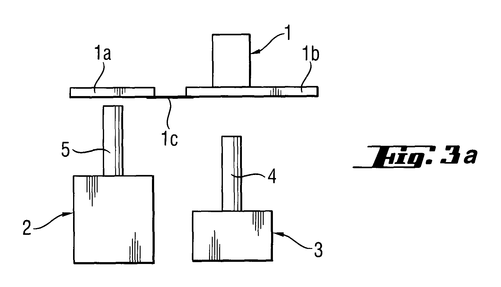
- FIG. 3a shows another embodiment variant with a pusher element 1, which is flexible in itself and consists of two rigid sub-elements 1a and 1b, through an elastic bridge 1c, for example a suitable material thinning are connected in one piece.
- the elastic bridge 1c can also be replaced by a knee-like joint, hinge or the like.
- the Both sub-elements 1a and 1b are rigid in themselves and serve as the drawing illustrates, on the one hand for actuating the actuator 5 and on the other hand the Sensor plunger 4. If the pusher element 1 is actuated (Fig. 3b), then - as before - First the switch 2 turned ON, the actuator 5 already in has essentially reached its final position.
- Another advantage of this embodiment is that the operator when pressing the pusher element 1 on the actuating finger clearly noticeable tactile information about the actuation of switch 2 on the one hand and only after that successively increasing print information about the Actuation of the sensor of the speed control device and thus one too receives tactile information about the approximate engine speed.
- a rotary knob 6 In the embodiment variants of the invention according to FIGS. 4, 5 and 6 that is Actuating element a rotary knob 6.
- the rotary knob 6 by a first angle in the direction of the arrow 8 rotated to the right, the actuator 5 is first pressed down and operates switch 2 to the ON position.
- the pestle 4 pulled upwards and generated in sensor 3, which in turn is a pressure sensor can be a displacement sensor or a combined displacement / pressure sensor, in particular Electrical control signal proportional to the displacement Speed setting.
- the illustration in Fig. 4b leaves a certain example Detect intermediate position at which switch 2 is turned ON, and the sensor 3 has approximately reached a maximum possible displacement, so that in this rotary knob position approximately maximum speed of the so equipped Power tool is reached.
- the sensor 3 consists of two separate ones Sub-elements or sub-assemblies that together form a sensor system form, for example from a permanent magnet fixed to the rotary knob 6 7, when turning the rotary knob 6 in the direction of rotation 8 and after switching ON of the switch 2 in the area of at least one or more the permanent magnet 7 arrives in a time sequence of excitable Hall elements 9, through which either an electronic speed control device is triggered, or - in the case of several Hall elements - a multi-digit binary signal for the direct specification of a certain speed.
- the sensor system 3 can also be replaced by another arrangement, for example by an electro-optical switching arrangement.
- the permanent magnet 7 may be replaced by a light-emitting element
- module 9 can be a linear receiver array, each after irradiation by the light-emitting element depending on the angle of rotation specifies a certain speed for driving the power tool.
- 6a / b corresponds essentially to the embodiment variant of the invention 5a / b, but with the difference that the ON / OFF switch 2 has an actuator 5 which is spring-loaded upwards in FIGS. 6a / b, that in the OFF position by a cam 10 present on the rotary knob 6 is pressed in. If the knob 6 is rotated in the direction of rotation 8, so the cam 10 releases the actuator 5, which now jumps up and the Switch 2 turns ON.
Landscapes
- Rotary Switch, Piano Key Switch, And Lever Switch (AREA)
- Push-Button Switches (AREA)
- Control Of Electric Motors In General (AREA)
- Portable Power Tools In General (AREA)
Abstract

Description
- Fig. 1
- in drei Betriebspositionen (Fig. 1a, 1b und 1c) eine drückerbetätigte Schalt- und Drehzahleinstelleinrichtung für Elektrowerkzeuge gemäß der Erfindung;
- Fig. 2
- eine abgewandelte Ausführungsvariante einer Schalt- und Drehzahleinstelleinrichtung mit unterschiedlichen Positionsstellungen gemäß Fig. 2a, 2b und 2c, die durch eine Druck- und Schiebebewegung eines Drückerelements zeitsequentiell betätigbar sind;
- Fig. 3
- eine weitere Ausführungsvariante einer Schalt- und Drehzahleinstelleinrichtung in drei Stellpositionen gemäß Fig. 3a, 3b und 3c nach der Erfindung, bei welcher ein gelenkiges Drückerelement zur zeitsequentiellen Betätigung eines EIN/AUS-Schalters einerseits und eines Sensors einer Drehzahl-Steuereinrichtung andererseits vorgesehen ist;
- Fig. 4
- eine Ausführungsvariante der Erfindung, bei der das Betätigungselement als Drehknopf in zwei Stellpositionen (Fig. 4a und 4b) ausgeführt ist;
- Fig. 5
- eine weitere Drehknopf-Variante mit einer anderen Art einer Drehzahleinstelleinrichtung in zwei Stellpositionen (Fig. 5a und 5b); und
- Fig. 6
- eine der Fig. 5 entsprechende Ausführungvariante mit Drehknopf in zwei Stellpositionen (Fig. 6a, 6b), bei welcher ein EIN/AUS-Schalter durch einen mit dem Drehknopf verstellbaren Nocken betätigt wird.
- Der Schalter 2 kann ein preiswertes handelsübliches Serienteil sein.
- Der zum Schalter 2 unmittelbar benachbart angeordnete Sensor 3 kann ein hermetisch verschlossenes und verschleißfrei arbeitendes Bauteil, oder eine aus zwei berührungsfrei zusammenwirkenden Elementen bestehendes Sensorsystem sein, das insbesondere für eine große Produktpalette von Elektrowerkzeugen in gleicher Ausführung als Serienteil bereitgestellt werden kann.
- Wie dem Benutzer schon von vielen auf dem Markt befindlichen handgeführten Elektrowerkzeugen bekannt, werden Schalter- und Drehzahleinstellung weiterhin von nur einem Drückerelement oder Drehknopf aus betätigt.
Claims (7)
- EIN/AUS-Schalt- und Drehzahleinstelleinrichtung für Elektrowerkzeuge gekennzeichent durch die funktionale Verbindung eines Schalters (2), der durch ein Betätigungselement (1, 5), bei dessen Bewegung von der AUS-Stellung über einen ersten Weg EIN-schaltbar ist, und einer separaten Drehzahl-Steuereinrichtung mit einem Sensor (3), der bei einer Weiterbewegung über den ersten Weg hinaus einen Druckwert bezogen auf die Momentanposition des Betätigungselements (1) und/oder den Weg des Betätigungselement (1) erfaßt und ein entsprechendes Drehzahl-Steuersignal für den Motor bereitstellt.
- EIN/AUS-Schalt- und Drehzahleinstelleinrichtung nach Anspruch 1, bei dem das Betätigungselement ein Drücker ist, dadurch gekennzeichnet, daß der Drücker (1) ein einseitig angelenktes Schwenkglied und der Schalter (2) als Druckschalter ausgebildet und näher zum Anlenkpunkt des Drückers (1) angeordnet ist als die zum Schalter unmittelbar benachbarte fixierte Drehzahl-steuereinrichtung, die ein Sensor-Betätigungsglied (4) aufweist, das vom bewegten Drücker (1) erst nach EIN-Schalten des Schalters (2) betätigbar ist.
- EIN/AUS-Schalt- und Drehzahleinstelleinrichtung nach Anspruch 2, dadurch gekennzeichnet, daß der Drücker als gelenkiges Schwenkglied (1a, 1b, 1c) ausgebildet ist.
- EIN/AUS-Schalt- und Drehzahleinstelleinrichtung nach Anspruch 1, dadurch gekennzeichnet, daß das Betätigungselement ein Drehknopf (6) ist, der beim Verdrehen um einen ersten Drehwinkel den Schalter (2) EIN-schaltet und beim Weiterdrehen im gleichen Drehsinn den Sensor (3) für die Drehzahlsteuerung aktiviert.
- EIN/AUS-Schalt- und Drehzahleinstelleinrichtung nach Anspruch 4, dadurch gekennzeichnet, daß der Sensor ein magnetischer Sensor ist, der durch einen mit dem Drehknopf (6) verbundenen Permanentmagneten (7) beim Verdrehen des Drehknopfs (6) über den ersten Drehwinkel hinaus aktivierbar ist, um die Drehzahl-Steuereinrichtung entsprechend dem weiteren Verdrehen des Drehknopfs (6) zu betätigen.
- EIN/AUS-Schalt- und Drehzahleinstelleinrichtung nach Anspruch 5, dadurch gekennzeichnet, daß der magnetische Sensor (3) ein Hall-Element (7) enthält.
- EIN/AUS-Schalt- und Drehzahleinstelleinrichtung nach Anspruch 4, dadurch gekennzeichnet, daß der Drehknopf (6) über einen mit diesem verbundenen Nocken (10) den Schalter (2) betätigt.
Applications Claiming Priority (2)
| Application Number | Priority Date | Filing Date | Title |
|---|---|---|---|
| DE1999142157 DE19942157A1 (de) | 1999-09-03 | 1999-09-03 | EIN/AUS-Schalt- oder Drehzahleinstelleinrichtung für Elektrowerkzeuge |
| DE19942157 | 1999-09-03 |
Publications (2)
| Publication Number | Publication Date |
|---|---|
| EP1081725A2 true EP1081725A2 (de) | 2001-03-07 |
| EP1081725A3 EP1081725A3 (de) | 2002-07-31 |
Family
ID=7920736
Family Applications (1)
| Application Number | Title | Priority Date | Filing Date |
|---|---|---|---|
| EP00810740A Withdrawn EP1081725A3 (de) | 1999-09-03 | 2000-08-21 | EIN/AUS-Schalt- und Drehzahleinstelleinrichtung für Elektrowerkzeuge |
Country Status (6)
| Country | Link |
|---|---|
| EP (1) | EP1081725A3 (de) |
| JP (1) | JP2001121449A (de) |
| KR (1) | KR20010050221A (de) |
| CN (1) | CN1287369A (de) |
| DE (1) | DE19942157A1 (de) |
| ZA (1) | ZA200004382B (de) |
Cited By (2)
| Publication number | Priority date | Publication date | Assignee | Title |
|---|---|---|---|---|
| WO2014013474A1 (en) * | 2012-07-20 | 2014-01-23 | Peter John Hosking | Power tools and hand operated electrical devices |
| US11897110B2 (en) | 2017-11-07 | 2024-02-13 | Milwaukee Electric Tool Corporation | Non-contact speed selector switch in rotary power tool |
Families Citing this family (11)
| Publication number | Priority date | Publication date | Assignee | Title |
|---|---|---|---|---|
| DE10259569A1 (de) * | 2002-12-19 | 2004-07-01 | Hilti Ag | Elektrohandwerkzeugmaschine mit kontaktlosem elektrischen Handschalter |
| DE10334884A1 (de) * | 2003-07-29 | 2005-03-10 | Alexander Muehlhaeuser | Schaltelement für die Drehrichtungs- und Drehzahlwahl von Elektrohandwerksmaschinen insbesondere Akkubohrmaschinen |
| DE102004020427A1 (de) * | 2004-04-27 | 2005-11-24 | Robert Bosch Gmbh | Elektrowerkzeug mit Bedienelementen zum Einstellen von Betriebsparametern |
| JP2007015045A (ja) * | 2005-07-06 | 2007-01-25 | Nidec Shibaura Corp | コードレス電動工具 |
| FR2935106B1 (fr) * | 2008-08-22 | 2010-09-17 | Pellenc Sa | Outil electroportatif a commande par gachette |
| JP5594227B2 (ja) * | 2011-02-17 | 2014-09-24 | トヨタ車体株式会社 | 動力工具 |
| PL3295844T3 (pl) | 2013-11-27 | 2025-11-24 | Versuni Holding B.V. | Sprzęt kuchenny ze sterowaniem prędkością |
| WO2018092225A1 (ja) * | 2016-11-16 | 2018-05-24 | 東京コスモス電機株式会社 | 可変抵抗器用スイッチ装置 |
| US11623335B2 (en) | 2017-11-15 | 2023-04-11 | Defond Components Limited | Control assembly for use in operation of an electric device |
| CN108320947B (zh) * | 2018-03-29 | 2023-06-20 | 莱克电气绿能科技(苏州)有限公司 | 一种电动工具的开关启动机构及电动工具 |
| KR102817579B1 (ko) * | 2019-03-15 | 2025-06-10 | 현대자동차주식회사 | 차량의 타이어 압력 모니터링 장치 및 그 방법 |
Family Cites Families (3)
| Publication number | Priority date | Publication date | Assignee | Title |
|---|---|---|---|---|
| DE2053848C3 (de) * | 1970-11-03 | 1978-10-26 | Baer Elektrowerke Kg, 5885 Schalksmuehle | Einbauschalter, insbesondere für Staubsauger |
| US5084598A (en) * | 1987-10-21 | 1992-01-28 | Omron Corporation | Electric switch for a power tool |
| DE3934950A1 (de) * | 1989-10-20 | 1991-04-25 | Marquardt Gmbh | Drehzahlregler fuer elektromotoren von elektrowerkzeugen |
-
1999
- 1999-09-03 DE DE1999142157 patent/DE19942157A1/de not_active Withdrawn
-
2000
- 2000-08-21 EP EP00810740A patent/EP1081725A3/de not_active Withdrawn
- 2000-08-24 ZA ZA200004382A patent/ZA200004382B/xx unknown
- 2000-08-26 KR KR1020000049823A patent/KR20010050221A/ko not_active Withdrawn
- 2000-08-28 CN CN 00124100 patent/CN1287369A/zh active Pending
- 2000-09-04 JP JP2000267221A patent/JP2001121449A/ja active Pending
Cited By (6)
| Publication number | Priority date | Publication date | Assignee | Title |
|---|---|---|---|---|
| WO2014013474A1 (en) * | 2012-07-20 | 2014-01-23 | Peter John Hosking | Power tools and hand operated electrical devices |
| EP2874773A4 (de) * | 2012-07-20 | 2016-05-25 | Peter John Hosking | Elektrowerkzeuge und handbetriebene elektrische vorrichtungen |
| AU2013291545B2 (en) * | 2012-07-20 | 2017-10-05 | Peter John Hosking | Power tools and hand operated electrical devices |
| US9914204B2 (en) | 2012-07-20 | 2018-03-13 | Peter John Hosking | Power tools and hand operated electrical devices |
| US11897110B2 (en) | 2017-11-07 | 2024-02-13 | Milwaukee Electric Tool Corporation | Non-contact speed selector switch in rotary power tool |
| US12208501B2 (en) | 2017-11-07 | 2025-01-28 | Milwaukee Electric Tool Corporation | Non-contact speed selector switch in rotary power tool |
Also Published As
| Publication number | Publication date |
|---|---|
| JP2001121449A (ja) | 2001-05-08 |
| KR20010050221A (ko) | 2001-06-15 |
| CN1287369A (zh) | 2001-03-14 |
| EP1081725A3 (de) | 2002-07-31 |
| DE19942157A1 (de) | 2001-03-08 |
| ZA200004382B (en) | 2001-02-28 |
Similar Documents
| Publication | Publication Date | Title |
|---|---|---|
| EP1895555A2 (de) | Handwerkzeugmaschine | |
| EP1873800B1 (de) | Elektrische Werkzeugmaschine und Schalter hierfür | |
| DE19942157A1 (de) | EIN/AUS-Schalt- oder Drehzahleinstelleinrichtung für Elektrowerkzeuge | |
| DE102016117783B4 (de) | Elektrischer Schalter | |
| DE112019004233T5 (de) | Auslöseschalter | |
| EP1436821B1 (de) | Mehrwege-schalteranordnung, sowie schalterbaustein | |
| DE4215097C2 (de) | Schalteranordnung | |
| DE102006007600B4 (de) | Drehsteller für elektrische oder elektronische Gräte in einem Kraftfahrzeug | |
| DE68916993T2 (de) | Kombination von Schalter und Sperrvorrichtung. | |
| EP0423673B1 (de) | Drehzahlregler für Elektromotoren von Elektrowerkzeugen | |
| EP1062673B1 (de) | Elektrischer schalter | |
| DE69228001T2 (de) | Sicherheitsschalter für arbeitsmaschinen | |
| EP0608771A1 (de) | Verfahren und Vorrichtung zum Betätigen von Einbaukomponenten in Kraftfahrzeugen | |
| DE19932578A1 (de) | Handführbare Vorrichtung zum Schleifen und/oder Trennen eines Werkstücks, insbesondere Winkelschleifer | |
| DE10297207B4 (de) | Sicherheitsschalteinrichtung für elektrisch gesteuerte Maschinen | |
| DE102016117785A1 (de) | Elektrischer Schalter | |
| EP1907916A1 (de) | Bedienelement mit zentralem taster | |
| EP1425770B1 (de) | Sollwerteinrichtung für Elektrogeräte | |
| DE19544467C1 (de) | Elektrische Signalgabeeinrichtung | |
| EP1472708B1 (de) | Elektrische schaltanordnung für ein elektrowerkzeug | |
| DE102008001154B4 (de) | Elektrohandwerkzeug mit einer Betätigungsvorrichtung und einem Antriebsmotor | |
| DE10036394B4 (de) | Bedieneinrichtung für ein elektrisch betriebenes Schiebedach eines Kraftfahrzeuges | |
| EP1702796B1 (de) | Kombinierter Druck- und Drehschalter für ein Kraftfahrzeug | |
| DE29708857U1 (de) | Stell- oder Betätigungsvorrichtung | |
| EP1021313A1 (de) | Elektrischer hebelschalter |
Legal Events
| Date | Code | Title | Description |
|---|---|---|---|
| PUAI | Public reference made under article 153(3) epc to a published international application that has entered the european phase |
Free format text: ORIGINAL CODE: 0009012 |
|
| AK | Designated contracting states |
Kind code of ref document: A2 Designated state(s): AT BE CH CY DE DK ES FI FR GB GR IE IT LI LU MC NL PT SE |
|
| AX | Request for extension of the european patent |
Free format text: AL;LT;LV;MK;RO;SI |
|
| PUAL | Search report despatched |
Free format text: ORIGINAL CODE: 0009013 |
|
| AK | Designated contracting states |
Kind code of ref document: A3 Designated state(s): AT BE CH CY DE DK ES FI FR GB GR IE IT LI LU MC NL PT SE |
|
| AX | Request for extension of the european patent |
Free format text: AL;LT;LV;MK;RO;SI |
|
| AKX | Designation fees paid | ||
| REG | Reference to a national code |
Ref country code: DE Ref legal event code: 8566 |
|
| STAA | Information on the status of an ep patent application or granted ep patent |
Free format text: STATUS: THE APPLICATION IS DEEMED TO BE WITHDRAWN |
|
| 18D | Application deemed to be withdrawn |
Effective date: 20030201 |