EP1081475A2 - Temperaturstabilisierbarer Infrarot-Sensor und Infrarot-Thermometer mit einem derartigen Sensor - Google Patents
Temperaturstabilisierbarer Infrarot-Sensor und Infrarot-Thermometer mit einem derartigen Sensor Download PDFInfo
- Publication number
- EP1081475A2 EP1081475A2 EP00117872A EP00117872A EP1081475A2 EP 1081475 A2 EP1081475 A2 EP 1081475A2 EP 00117872 A EP00117872 A EP 00117872A EP 00117872 A EP00117872 A EP 00117872A EP 1081475 A2 EP1081475 A2 EP 1081475A2
- Authority
- EP
- European Patent Office
- Prior art keywords
- infrared sensor
- infrared
- heating
- window
- housing
- Prior art date
- Legal status (The legal status is an assumption and is not a legal conclusion. Google has not performed a legal analysis and makes no representation as to the accuracy of the status listed.)
- Granted
Links
Images

Classifications
-
- G—PHYSICS
- G01—MEASURING; TESTING
- G01J—MEASUREMENT OF INTENSITY, VELOCITY, SPECTRAL CONTENT, POLARISATION, PHASE OR PULSE CHARACTERISTICS OF INFRARED, VISIBLE OR ULTRAVIOLET LIGHT; COLORIMETRY; RADIATION PYROMETRY
- G01J5/00—Radiation pyrometry, e.g. infrared or optical thermometry
-
- G—PHYSICS
- G01—MEASURING; TESTING
- G01J—MEASUREMENT OF INTENSITY, VELOCITY, SPECTRAL CONTENT, POLARISATION, PHASE OR PULSE CHARACTERISTICS OF INFRARED, VISIBLE OR ULTRAVIOLET LIGHT; COLORIMETRY; RADIATION PYROMETRY
- G01J5/00—Radiation pyrometry, e.g. infrared or optical thermometry
- G01J5/02—Constructional details
- G01J5/04—Casings
-
- G—PHYSICS
- G01—MEASURING; TESTING
- G01J—MEASUREMENT OF INTENSITY, VELOCITY, SPECTRAL CONTENT, POLARISATION, PHASE OR PULSE CHARACTERISTICS OF INFRARED, VISIBLE OR ULTRAVIOLET LIGHT; COLORIMETRY; RADIATION PYROMETRY
- G01J5/00—Radiation pyrometry, e.g. infrared or optical thermometry
- G01J5/0003—Radiation pyrometry, e.g. infrared or optical thermometry for sensing the radiant heat transfer of samples, e.g. emittance meter
-
- G—PHYSICS
- G01—MEASURING; TESTING
- G01J—MEASUREMENT OF INTENSITY, VELOCITY, SPECTRAL CONTENT, POLARISATION, PHASE OR PULSE CHARACTERISTICS OF INFRARED, VISIBLE OR ULTRAVIOLET LIGHT; COLORIMETRY; RADIATION PYROMETRY
- G01J5/00—Radiation pyrometry, e.g. infrared or optical thermometry
- G01J5/0003—Radiation pyrometry, e.g. infrared or optical thermometry for sensing the radiant heat transfer of samples, e.g. emittance meter
- G01J5/0011—Ear thermometers
-
- G—PHYSICS
- G01—MEASURING; TESTING
- G01J—MEASUREMENT OF INTENSITY, VELOCITY, SPECTRAL CONTENT, POLARISATION, PHASE OR PULSE CHARACTERISTICS OF INFRARED, VISIBLE OR ULTRAVIOLET LIGHT; COLORIMETRY; RADIATION PYROMETRY
- G01J5/00—Radiation pyrometry, e.g. infrared or optical thermometry
- G01J5/02—Constructional details
-
- G—PHYSICS
- G01—MEASURING; TESTING
- G01J—MEASUREMENT OF INTENSITY, VELOCITY, SPECTRAL CONTENT, POLARISATION, PHASE OR PULSE CHARACTERISTICS OF INFRARED, VISIBLE OR ULTRAVIOLET LIGHT; COLORIMETRY; RADIATION PYROMETRY
- G01J5/00—Radiation pyrometry, e.g. infrared or optical thermometry
- G01J5/02—Constructional details
- G01J5/04—Casings
- G01J5/041—Mountings in enclosures or in a particular environment
- G01J5/045—Sealings; Vacuum enclosures; Encapsulated packages; Wafer bonding structures; Getter arrangements
-
- G—PHYSICS
- G01—MEASURING; TESTING
- G01J—MEASUREMENT OF INTENSITY, VELOCITY, SPECTRAL CONTENT, POLARISATION, PHASE OR PULSE CHARACTERISTICS OF INFRARED, VISIBLE OR ULTRAVIOLET LIGHT; COLORIMETRY; RADIATION PYROMETRY
- G01J5/00—Radiation pyrometry, e.g. infrared or optical thermometry
- G01J5/02—Constructional details
- G01J5/06—Arrangements for eliminating effects of disturbing radiation; Arrangements for compensating changes in sensitivity
- G01J5/061—Arrangements for eliminating effects of disturbing radiation; Arrangements for compensating changes in sensitivity by controlling the temperature of the apparatus or parts thereof, e.g. using cooling means or thermostats
-
- G—PHYSICS
- G01—MEASURING; TESTING
- G01J—MEASUREMENT OF INTENSITY, VELOCITY, SPECTRAL CONTENT, POLARISATION, PHASE OR PULSE CHARACTERISTICS OF INFRARED, VISIBLE OR ULTRAVIOLET LIGHT; COLORIMETRY; RADIATION PYROMETRY
- G01J5/00—Radiation pyrometry, e.g. infrared or optical thermometry
- G01J5/02—Constructional details
- G01J5/06—Arrangements for eliminating effects of disturbing radiation; Arrangements for compensating changes in sensitivity
- G01J5/064—Ambient temperature sensor; Housing temperature sensor; Constructional details thereof
-
- G—PHYSICS
- G01—MEASURING; TESTING
- G01J—MEASUREMENT OF INTENSITY, VELOCITY, SPECTRAL CONTENT, POLARISATION, PHASE OR PULSE CHARACTERISTICS OF INFRARED, VISIBLE OR ULTRAVIOLET LIGHT; COLORIMETRY; RADIATION PYROMETRY
- G01J5/00—Radiation pyrometry, e.g. infrared or optical thermometry
- G01J5/02—Constructional details
- G01J5/08—Optical arrangements
-
- G—PHYSICS
- G01—MEASURING; TESTING
- G01J—MEASUREMENT OF INTENSITY, VELOCITY, SPECTRAL CONTENT, POLARISATION, PHASE OR PULSE CHARACTERISTICS OF INFRARED, VISIBLE OR ULTRAVIOLET LIGHT; COLORIMETRY; RADIATION PYROMETRY
- G01J5/00—Radiation pyrometry, e.g. infrared or optical thermometry
- G01J5/02—Constructional details
- G01J5/08—Optical arrangements
- G01J5/0875—Windows; Arrangements for fastening thereof
Definitions
- the invention relates to a temperature-stabilizable infrared sensor and an infrared thermometer with such a sensor, in particular for fever measurement in the ear.
- DE 199 13 672 describes an infrared thermometer with a measuring tip, one Infrared waveguide and a radiation sensor arranged at its end.
- the Measuring tip and / or a protective cap which can be placed on the measuring tip in a manner known per se are / is designed so that only the front area of the measuring tip or the protective cap can be heated to a temperature which corresponds approximately to the normal ear canal temperature.
- There the infrared sensor in the measuring tip has only a limited field of view, it is sufficient to reduce measurement errors if only the part of the measuring tip has the same temperature as the ear canal in the field of view of the infrared sensor lying part of the ear canal interacts thermally.
- the relatively small heatable The area can only be heated in an energy-saving manner if it is opposite the unheatable one Part of the probe tip is thermally insulated, which, however, changes the structure of the probe tip complicated.
- a radiation detector with a thermistor that of two Heating elements is kept at a constant temperature.
- the capsule is from surround a housing that has a radiation-transparent window through which the Detecting radiation into the housing and through a hole in one of the heating elements in the Capsule and can get to the thermistor.
- This radiation detector is only very complex producible and therefore correspondingly expensive.
- From US-A-5,010,315 is a thermal radiation sensor element with two NTC resistors known, the temperature of which is kept constant by one heating layer each. Between Heating layers and the NTC resistors are arranged insulating layers.
- thermopile sensor with a housing which is a radiation-permeable Window.
- a sensor element on a carrier body arranged, which is provided with a central bore spanned by a membrane is.
- the cold spots and the hot spots of the sensor element are on the membrane, namely the cold spots in the area of the support body and the hot spots in the area of Drilling. Only the hot spots can be heated by at least one heating element.
- the object of the present invention is a simple heatable and / or coolable Infrared sensor and an infrared thermometer with a particularly simple structure to specify.
- An infrared sensor has at least one infrared sensor element, a heating and / or Cooling element and a housing with an infrared-transmissive window.
- the For example, window can be made of a chalcogenite glass that is transparent to infrared and is easy to shape.
- the sensor element is arranged in the housing so that infrared light can pass through the window can reach the sensor element.
- the heating / cooling element is with the window and / or the housing is connected in a heat-conducting manner. It is particularly advantageous if that Housing is constructed so that only minimal temperature gradients within the housing may occur.
- the heating / cooling element is therefore preferably arranged such that the housing and the window heat up evenly when heating or cooling or cooling down.
- the window and the housing are therefore preferably thermally conductive to one another connected and consist of materials with high thermal conductivity, such as that Copper case and silicon window.
- heating / cooling element are, for example a heating element designed as an NTC or PTC resistor or transistor and a heating and cooling element designed as a Peltier element is also meant.
- the heating / cooling element is preferably electrically heated or cooled.
- the heating / cooling element is preferably attached to the housing of the infrared sensor. It can also consist of a film, for example a polyimide film, on which a conductor track-shaped Metal layer, for example made of aluminum, copper, gold or a chrome / nickel alloy, or a silver / graphite paste is applied.
- a heating element that, for example a conductor track-shaped metal layer or a layer of an electrically conductive Plastic exists, can also be applied directly to the window.
- Another one Execution of an infrared sensor according to the invention is the window through a heating wire from, for example, constantan, which runs around the window and is good with it is thermally connected.
- the window consists of a semiconductor, especially silicon, in which is formed by doping an electrical conductor track, which acts as a resistance heating element can serve.
- the infrared sensor has at least one temperature sensor, which is preferably in itself is known to be thermally conductively connected to the infrared sensor element.
- the heating / cooling element itself is an embodiment of an infrared sensor according to the invention Temperature sensor used. If the infrared sensor element consists of a thermopile, then can, in a manner known per se from EP 0502277, also the thermopile itself as a temperature sensor serve.
- the infrared sensor then has connections for the infrared sensor element (s) and for the heating element (s). If the heating element or infrared sensor element is not also used as a temperature sensor, the infrared sensor also has additional Connections for the temperature sensor.
- the temperature sensor is via its connections connectable to a control device.
- the control device determines from measurable parameters of the temperature sensor, Heating / cooling element or infrared sensor element, e.g. the electrical resistance, the threshold voltage or the forward voltage, the temperature of the temperature sensor and thus also that of the infrared sensor.
- the control device preferably contains for each Heating / cooling element is a control circuit that depends on an adjustable temperature setpoint the heating element (s) for heating, cooling and / or keeping the Temperature supplies the necessary energy. In this way, the infrared sensor can be set to a certain temperature brought and temperature stabilized.
- the control device is can also be connected to an energy source, for example a battery.
- the control device can also be arranged in the infrared sensor, which then apart from the connections for the infrared sensor element (s) connections for entering a temperature setpoint and for connection to an energy source.
- the infrared sensor contains one or more infrared sensor element (s), in particular thermopile (s), as they are known per se from the prior art.
- infrared sensor element in particular thermopile (s)
- thermopile thermopile
- an infrared sensor with two infrared-sensitive elements known from which one is shielded from infrared radiation By comparing the two Elements supplied signals can be obtained a measurement signal that corresponds to the amount of the incident Infrared radiation corresponds and largely free of electrical noise and thermal Disorders.
- the infrared sensor element (s) can also be the one from DE 197 10 946 have known structure.
- an infrared sensor there are several Infrared sensor elements arranged in a matrix.
- the window of this infrared sensor is then preferably designed as a lens.
- the infrared sensor elements are preferably located in the focal plane of the lens.
- the infrared sensor is directly on the front Arranged end of a measuring tip.
- the advantage of this design is that heatable / coolable infrared sensor then practically the entire front end of the measuring tip, or at least brought the end face of the measuring tip to the desired temperature become, and therefore the thermal equilibrium when inserting the probe into the ear canal is practically not disturbed in the ear canal, and measurement errors are thereby avoided.
- the Measuring tip can have a shape or structure known per se, especially be flexible. As an example of such a probe tip, EP 0588631 A2, which describes a flexible measuring tip, the flexibility of which is based on its outer circumference formed slot or bellows is increased.
- the probe tip can also have ribs, depressions or the like on their outside.
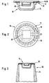
- FIG. 1 shows a first infrared sensor 10 according to the invention with an infrared-transparent one Housing 12 having window 12.
- Window 12 preferably consists of Silicon.
- a heating element 16 and a temperature sensor 18 are formed in the window 12.
- On Infrared sensor element 20 for converting the detected infrared radiation into an electrical one Output signal is attached to window 12 within housing 14.
- two connections 22 are provided at the edge of the window 12.
- the output signals of the infrared sensor element 20 and the temperature sensor 18 can evaluated by means of measuring electronics, not shown in the figure, and via one in the Figure not shown display device shows a measured radiation temperature become.
- the window 12 is in the form of a disk.
- the heating element 16 has a conductor track shape and is arranged in a ring on the edge of the window 12.
- the temperature sensor 18 also has a conductor-shape and runs further inside parallel to the heating element 16. Because of the spatial proximity between the heating element 16 and the temperature sensor 18, the temperature of the infrared sensor 10 regulate very precisely and with low inertia.
- the infrared sensor element 20, preferably a or more thermopile (s) is located in the middle of the window 12.
- the first measuring tip 30, shown schematically in FIG. 3, of an infrared thermometer according to the invention has at its front end the infrared sensor shown in Figures 1 and 2 10 on. This is held on its window 12 by means of a metal ring 32.
- the Metal ring is attached to a shaft 34, which is preferably made of a plastic, whose outer shape and dimensions are adapted to the human ear canal.
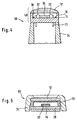
- Fig. 4 shows a second measuring tip 50 of an infrared thermometer according to the invention, in which a second infrared sensor 40 according to the invention is placed directly on the shaft 34, so that the entire front end of the measuring tip 50 is formed by the infrared sensor 40 and can be heated or is coolable.
- This has an outwardly curved window 12 ', the incident one Infrared radiation onto a preferably matrix-shaped arrangement 24 comprising a plurality of infrared sensor elements depicts.
- the heating / cooling element 16, the temperature sensor 18 and the Infrared sensor elements are on the inside on the bottom of the housing 14 of the infrared sensor 40 arranged.
- the arrangement 24 of infrared sensor elements can also be attached to a foil (not shown), whereby preferably on the top of the film, the arrangement 24 of infrared sensor elements is located, and on the underside of the film at least one heating / cooling element and possibly one Temperature sensor in the form of one or more conductor tracks that connect to the bottom of the Housing are well connected to heat.
- the connections 22 of the arrangement 24 of infrared sensor elements are only shown schematically, and via pins 21 to the outside guided.
- FIG. 5 shows a third measuring tip 60 of an infrared thermometer according to the invention with a third infrared sensor according to the invention.
- the measuring tip has a shaft 34 into which the Infrared sensor is used, so that the side walls 26 of the infrared sensor and the outer Edge of the window 12 are surrounded by the shaft 34.
- An infrared sensor element 20 or one The arrangement of several infrared sensor elements is opposite the window 12 on the housing base 28 of the infrared sensor arranged.
- the infrared sensor element is preferably made from a thermopile.
- a temperature sensor, not shown in FIG. 5, is in itself arranged in a known manner near the cold spots of the thermopile. Also on the case back 28 but outside the housing of the infrared sensor is a heating and / or Cooling element 16 attached.
- FIG. 6 shows a fourth infrared sensor 70 according to the invention with an upper housing part 27, an infrared-transmissive window 12 and a housing bottom 28.
- An infrared sensor element 20 or an arrangement of several infrared sensor elements and a temperature sensor 18 is mounted on a frame 23 within the housing.
- the connections 22 of the Infrared sensor element 20 and temperature sensor 18 are only shown schematically, and via pins 21 through bushings 29 in the housing base 28 to the outside guided.
- the heating / cooling element 16 is attached to a heat distribution plate 15 which is on the outside Housing bottom 28 is attached in a heat-conducting manner. But it can also elsewhere in the Housing be attached.
- the upper housing part 27 has an opening that from the window 12 is closed.
- the side walls 25 of the opening are chamfered so that Fixed 12 penetrating infrared radiation in the direction of the infrared sensor element 20 is reflected.
Landscapes
- Physics & Mathematics (AREA)
- General Physics & Mathematics (AREA)
- Spectroscopy & Molecular Physics (AREA)
- Radiation Pyrometers (AREA)
- Photometry And Measurement Of Optical Pulse Characteristics (AREA)
- Measuring And Recording Apparatus For Diagnosis (AREA)
- Polyurethanes Or Polyureas (AREA)
- Paints Or Removers (AREA)
Abstract
Description
Claims (15)
- Infrarot-Sensor mit mindestens einem Infrarot-Sensorelement (20; 24), mindestens einem Heiz- und/oder Kühlelement (16) und einem Gehäuse (14; 26, 27, 28), das ein infrarotdurchlässiges Fenster (12) aufweist, wobei das Heiz/Kühlelement (16) mit dem Fenster (12) und/oder dem Gehäuse (14; 26, 27, 28) wärmeleitend verbunden ist.
- Infrarot-Sensor nach Anspruch 1, dadurch gekennzeichnet, daß er mindestens einen Temperatursensor (18) aufweist, der mit dem Sensorelement (20) und/oder dem Fenster (12) und/oder dem Gehäuse (14; 26, 27, 28) wärmeleitend verbunden ist.
- Infrarot-Sensor nach Anspruch 2, dadurch gekennzeichnet, daß das Heiz/Kühlelement (16) oder das Infrarot-Sensorelement (20) als Temperatursensor (18) verwendbar ist.
- Infrarot-Sensor nach Anspruch 2 oder 3, dadurch gekennzeichnet, daß das Fenster (12) aus einem Halbleiter besteht, und daß das Heizelement (16) und/oder der Temperatursensor (18) im Fenster durch Dotierung eines leiterbahnförmigen Bereichs gebildet ist.
- Infrarot-Sensor nach Anspruch 2 oder 3, dadurch gekennzeichnet, daß das Heiz- und/oder Kühlelement (16) und/oder der Temperatursensor (18) aus einer auf eine Folie aufgebrachten Leiterbahn oder Paste bestehen.
- Infrarot-Sensor nach Anspruch 5, dadurch gekennzeichnet, daß die Sensorelemente (20) auf der Oberseite einer Folie angeordnet sind, und daß auf der Unterseite der Folie das Heiz/Kühlelement (16) und/oder der Temperatursensor (18) angeordnet ist/sind.
- Infrarot-Sensor nach Anspruch 1, 2 oder 3, dadurch gekennzeichnet, daß das Heiz- und/oder Kühlelement (16) mit einer Wärmeverteilplatte (15) wärmeleitend verbunden ist, und die Wärmeverteilplatte (15) mit dem Gehäuse wärmeleitend verbunden ist.
- Infrarot-Sensor nach einem der vorhergehenden Ansprüche, dadurch gekennzeichnet, daß das Fenster (12) und das Gehäuse (14; 26, 27, 28) wärmeleitend miteinander verbunden sind und aus Materialien mit hoher Wärmeleitfähigkeit bestehen.
- Infrarot-Sensor nach einem der vorhergehenden Ansprüche, dadurch gekennzeichnet, daß das Fenster (12) als Linse ausgebildet ist.
- Infrarot-Sensor nach einem der vorhergehenden Ansprüche, dadurch gekennzeichnet, daß ein Gehäuseoberteil (27) des Infrarot-Sensors eine Öffnung aufweist, deren Seitenwände (25) abgeschrägt sind.
- Infrarot-Sensor nach Anspruch 9 oder 10, dadurch gekennzeichnet, daß das Infrarot-Sensorelement (20) oder die Infrarot-Sensorelemente der Anordnung (24) aus mindestens einem Thermopile bestehen.
- Infrarot-Thermometer, insbesondere zur Fiebermessung im Ohr, mit einer Meßspitze und einem Infrarot-Sensor nach einem der vorhergehenden Ansprüche, der am vorderen Ende der Meßspitze angeordnet ist.
- Infrarot-Thermometer nach Anspruch 12 oder Infrarot-Sensor nach einem der Ansprüche 1 bis 11, dadurch gekennzeichnet, daß es/er eine Steuereinrichtung zur Regelung der Heiz/Kühlleistung des Heiz- und/oder Kühlelements (16) aufweist.
- Infrarot-Thermometer oder Infrarot-Sensor nach Anspruch 13, dadurch gekennzeichnet, daß durch die Steuereinrichtung die Temperatur des Infrarot-Sensors durch Messung bestimmter Kenngrößen des Heiz/Kühlelements (16) oder des Infrarot-Sensorelements (20) oder des Temperatursensors (18) ermittelbar ist.
- Infrarot-Thermometer nach Anspruch 12, dadurch gekennzeichnet, daß die Meßspitze biegsam ist.
Applications Claiming Priority (2)
| Application Number | Priority Date | Filing Date | Title |
|---|---|---|---|
| DE19942214 | 1999-09-03 | ||
| DE19942214A DE19942214A1 (de) | 1999-09-03 | 1999-09-03 | Beheizbarer Infrarot-Sensor und Infrarot-Thermometer mit einem derartigen Sensor |
Publications (3)
| Publication Number | Publication Date |
|---|---|
| EP1081475A2 true EP1081475A2 (de) | 2001-03-07 |
| EP1081475A3 EP1081475A3 (de) | 2003-02-12 |
| EP1081475B1 EP1081475B1 (de) | 2005-10-12 |
Family
ID=7920780
Family Applications (1)
| Application Number | Title | Priority Date | Filing Date |
|---|---|---|---|
| EP00117872A Expired - Lifetime EP1081475B1 (de) | 1999-09-03 | 2000-08-19 | Temperaturstabilisierbarer Infrarot-Sensor und Infrarot-Thermometer mit einem derartigen Sensor |
Country Status (8)
| Country | Link |
|---|---|
| US (1) | US6626835B1 (de) |
| EP (1) | EP1081475B1 (de) |
| JP (1) | JP4619499B2 (de) |
| KR (1) | KR100628283B1 (de) |
| CN (1) | CN1196918C (de) |
| AT (1) | ATE306652T1 (de) |
| DE (2) | DE19942214A1 (de) |
| TW (1) | TW496951B (de) |
Cited By (6)
| Publication number | Priority date | Publication date | Assignee | Title |
|---|---|---|---|---|
| WO2002066947A1 (de) * | 2001-02-19 | 2002-08-29 | Braun Gmbh | STRAHLUNGS-THERMOMETER MIT BEHEIZTER MEßSPITZE |
| WO2004055488A1 (en) * | 2002-12-12 | 2004-07-01 | Sherwood Services Ag | Thermal tympanic thermometer tip |
| DE10341433A1 (de) * | 2003-09-09 | 2005-03-31 | Braun Gmbh | Beheizbarer Infrarot-Sensor und Infrarot-Thermometer mit einem derartigen Infrarot-Sensor |
| DE102004050451A1 (de) * | 2004-09-18 | 2006-03-23 | Braun Gmbh | Strahlungsmeßgerät sowie Verfahren und Einrichtung zur Überprüfung der ordnungsgemäßen Funktionsweise des Strahlungsmeßgeräts |
| EP1857795A3 (de) * | 2006-05-19 | 2008-01-09 | Covidien AG | Trommelfellthermometer |
| FR2915571A1 (fr) * | 2007-04-27 | 2008-10-31 | Actherm Inc | Thermometre infrarouge. |
Families Citing this family (29)
| Publication number | Priority date | Publication date | Assignee | Title |
|---|---|---|---|---|
| KR100363284B1 (ko) * | 2001-05-22 | 2002-12-11 | 주식회사 메타텍 | 적외선 체온계 |
| JP3882645B2 (ja) * | 2002-03-06 | 2007-02-21 | 株式会社デンソー | 赤外線センサ |
| JP2004045330A (ja) * | 2002-07-15 | 2004-02-12 | Ricoh Co Ltd | 非接触温度検知装置 |
| DE102005033506A1 (de) * | 2005-07-14 | 2006-06-14 | Braun Gmbh | Verfahren zur Temperaturmessung mit geheizter Meßspitze |
| US8417304B2 (en) * | 2007-03-20 | 2013-04-09 | Pioneer Corporation | Biological information measuring apparatus |
| US7881625B2 (en) * | 2007-04-02 | 2011-02-01 | Kabushiki Kaisha Toshiba | Fixing device with non-contact temperature sensor and contact temperature sensor |
| US8785856B2 (en) * | 2010-07-08 | 2014-07-22 | Cvg Management Corporation | Infrared temperature measurement and stabilization thereof |
| CN102485166A (zh) * | 2010-12-03 | 2012-06-06 | 优盛医学科技股份有限公司 | 红外线温度计测量温度的方法 |
| DE102011009128B4 (de) | 2011-01-21 | 2015-11-19 | Excelitas Technologies Singapore Pte Ltd | Heizung für einen Sensor, beheizter Strahlungssensor, Strahlungserfassungsverfahren |
| CN102613961A (zh) * | 2011-01-31 | 2012-08-01 | 深圳市金亿帝科技有限公司 | 红外体温计 |
| CN102727189B (zh) * | 2011-04-12 | 2014-08-20 | 深圳市金亿帝科技有限公司 | 一种红外体温计测量方法 |
| DE112012003908T5 (de) * | 2011-09-20 | 2014-07-03 | Drs Rsta, Inc. | Thermische Isolationsvorrichtung für eine Infrarot-Überwachungskamera |
| CN102743161B (zh) * | 2012-05-08 | 2015-08-19 | 深圳市东迪欣科技有限公司 | 一种红外体温计及其提示方法 |
| US10677656B2 (en) | 2012-12-31 | 2020-06-09 | Flir Systems, Inc. | Devices and methods for infrared reference pixels |
| US9606016B2 (en) * | 2012-12-31 | 2017-03-28 | Flir Systems, Inc. | Devices and methods for determining vacuum pressure levels |
| JP6631775B2 (ja) | 2014-08-11 | 2020-01-15 | 日本電気硝子株式会社 | 赤外線透過ガラス |
| JP6701544B2 (ja) * | 2014-08-11 | 2020-05-27 | 日本電気硝子株式会社 | 赤外線透過ガラス |
| CN105982650B (zh) * | 2015-03-04 | 2019-02-15 | 百略医学科技股份有限公司 | 红外线温度计 |
| JP6359178B2 (ja) * | 2015-03-23 | 2018-07-18 | 三菱電機株式会社 | 空気調和機 |
| CN106137142A (zh) * | 2016-08-01 | 2016-11-23 | 东莞市嵘丰医疗器械有限公司 | 一种自调节初始温度的耳温枪及其温控方法 |
| EP3568679B1 (de) * | 2017-01-11 | 2021-03-10 | Koninklijke Philips N.V. | Integrierter temperatursensor auf einer blei-selenid-plattendetektoranordnung |
| CN108731800B (zh) | 2017-04-24 | 2020-07-10 | 清华大学 | 光强分布的检测系统 |
| US10935256B2 (en) * | 2018-04-09 | 2021-03-02 | Suarez Corporation Industries | Climate control device |
| CN108469414A (zh) * | 2018-06-25 | 2018-08-31 | 中国科学院地球化学研究所 | 一种适用于高温高压反应的便携式可视化加热和冷却装置 |
| CN112113664A (zh) * | 2019-06-19 | 2020-12-22 | 孙春元 | 红外温度传感器及包括其的探头、红外体温计 |
| US12019230B2 (en) * | 2019-06-27 | 2024-06-25 | Bae Systems Information And Electronic Systems Integration Inc. | System and method for a precision variable focus telescope |
| CN111562017A (zh) * | 2020-06-17 | 2020-08-21 | 清华大学 | 包含环境适应性控温和测温方法的人体温度筛查机器人 |
| CN112013965A (zh) * | 2020-08-06 | 2020-12-01 | 中国船舶工业系统工程研究院 | 红外测温探头工装 |
| JP7668716B2 (ja) * | 2021-09-30 | 2025-04-25 | 双葉電子工業株式会社 | 温度センサ |
Family Cites Families (29)
| Publication number | Priority date | Publication date | Assignee | Title |
|---|---|---|---|---|
| GB1127944A (en) * | 1966-03-15 | 1968-09-18 | Ass Portland Cement | Improvements relating to pyrometer |
| DD147872B1 (de) * | 1979-12-17 | 1983-09-21 | Akad Wissenschaften Ddr | Strahlungsdetektor fuer absolutmessungen |
| GB2090054A (en) * | 1980-12-23 | 1982-06-30 | Philips Electronic Associated | Radiation detector |
| US4602642A (en) * | 1984-10-23 | 1986-07-29 | Intelligent Medical Systems, Inc. | Method and apparatus for measuring internal body temperature utilizing infrared emissions |
| JPS6351231U (de) * | 1986-09-22 | 1988-04-06 | ||
| GB8628610D0 (en) * | 1986-11-29 | 1987-01-07 | Emi Plc Thorn | Temperature sensing arrangement |
| DE3709201A1 (de) * | 1987-03-20 | 1988-09-29 | Bosch Gmbh Robert | Waermestrahlungssensor |
| JPS6435326A (en) * | 1987-07-31 | 1989-02-06 | Chino Corp | Temperature detector |
| JPH0695050B2 (ja) * | 1987-08-06 | 1994-11-24 | 松下電器産業株式会社 | 赤外線透過窓の封着方法 |
| US4907895A (en) * | 1988-03-31 | 1990-03-13 | Ivac Corporation | Optical chopper for infrared thermometer |
| US4900162A (en) * | 1989-03-20 | 1990-02-13 | Ivac Corporation | Infrared thermometry system and method |
| US5081358A (en) * | 1990-02-23 | 1992-01-14 | Shimadzu Corporation | Detector of fourier transform infrared spectrometer |
| JPH03117739U (de) * | 1990-03-16 | 1991-12-05 | ||
| JPH03273121A (ja) | 1990-03-23 | 1991-12-04 | Citizen Watch Co Ltd | 放射体温計 |
| JPH03273689A (ja) * | 1990-03-23 | 1991-12-04 | Tokin Corp | 高感度サーモパイル |
| JPH0415025U (de) * | 1990-05-25 | 1992-02-06 | ||
| US5127742A (en) * | 1991-04-19 | 1992-07-07 | Thermoscan Inc. | Apparatus and method for temperature measurement by radiation |
| JPH04335120A (ja) * | 1991-05-10 | 1992-11-24 | Toshiba Corp | 赤外線検出器 |
| JPH05133803A (ja) * | 1991-11-14 | 1993-05-28 | Matsushita Electric Works Ltd | 赤外線検出素子 |
| DE69313337T2 (de) * | 1992-04-17 | 1998-01-02 | Terumo Corp | Infrarotsensor und Verfahren für dessen Herstellung |
| JP2601398B2 (ja) * | 1993-06-03 | 1997-04-16 | 愛知計装株式会社 | 低温物体の非接触高速温度測定方法及び装置 |
| WO1995022928A1 (en) * | 1994-02-28 | 1995-08-31 | Economation, Inc. | Infrared tympanic thermometer |
| JP3273121B2 (ja) | 1996-06-19 | 2002-04-08 | ブラザー工業株式会社 | 通信装置 |
| US5874736A (en) * | 1996-10-25 | 1999-02-23 | Exergen Corporation | Axillary infrared thermometer and method of use |
| DE19710946A1 (de) * | 1997-03-15 | 1998-09-24 | Braun Ag | Thermopile-Sensor und Strahlungsthermometer mit einem Thermopile-Sensor |
| JP3764565B2 (ja) * | 1997-09-02 | 2006-04-12 | 株式会社堀場製作所 | 熱型赤外線検出器 |
| JPH11258055A (ja) * | 1998-03-12 | 1999-09-24 | Omron Corp | サーモパイル型温度センサ |
| JP3855458B2 (ja) * | 1998-05-25 | 2006-12-13 | 松下電工株式会社 | 放射温度検出素子 |
| DE19913672A1 (de) * | 1999-03-25 | 2000-11-02 | Braun Gmbh | Infrarot-Thermometer mit einer beheizbaren Meßspitze und Schutzkappe |
-
1999
- 1999-09-03 DE DE19942214A patent/DE19942214A1/de not_active Withdrawn
-
2000
- 2000-08-19 EP EP00117872A patent/EP1081475B1/de not_active Expired - Lifetime
- 2000-08-19 AT AT00117872T patent/ATE306652T1/de not_active IP Right Cessation
- 2000-08-19 DE DE50011321T patent/DE50011321D1/de not_active Expired - Lifetime
- 2000-08-24 TW TW089117023A patent/TW496951B/zh not_active IP Right Cessation
- 2000-08-31 KR KR1020000050974A patent/KR100628283B1/ko not_active Expired - Lifetime
- 2000-08-31 CN CNB001243233A patent/CN1196918C/zh not_active Expired - Lifetime
- 2000-09-04 JP JP2000267568A patent/JP4619499B2/ja not_active Expired - Lifetime
- 2000-09-05 US US09/655,354 patent/US6626835B1/en not_active Expired - Lifetime
Cited By (11)
| Publication number | Priority date | Publication date | Assignee | Title |
|---|---|---|---|---|
| WO2002066947A1 (de) * | 2001-02-19 | 2002-08-29 | Braun Gmbh | STRAHLUNGS-THERMOMETER MIT BEHEIZTER MEßSPITZE |
| US7014358B2 (en) | 2001-02-19 | 2006-03-21 | Braun Gmbh | Radiation thermometer comprising a heated measuring tip |
| WO2004055488A1 (en) * | 2002-12-12 | 2004-07-01 | Sherwood Services Ag | Thermal tympanic thermometer tip |
| US7108419B2 (en) | 2002-12-12 | 2006-09-19 | Sherwood Services Ag | Thermal tympanic thermometer tip |
| US7434991B2 (en) | 2002-12-12 | 2008-10-14 | Covidien Ag | Thermal tympanic thermometer |
| DE10341433A1 (de) * | 2003-09-09 | 2005-03-31 | Braun Gmbh | Beheizbarer Infrarot-Sensor und Infrarot-Thermometer mit einem derartigen Infrarot-Sensor |
| US8115139B2 (en) | 2003-09-09 | 2012-02-14 | Kaz Usa, Inc. | Heatable infrared sensor and infrared thermometer comprising such an infrared sensor |
| DE102004050451A1 (de) * | 2004-09-18 | 2006-03-23 | Braun Gmbh | Strahlungsmeßgerät sowie Verfahren und Einrichtung zur Überprüfung der ordnungsgemäßen Funktionsweise des Strahlungsmeßgeräts |
| EP1857795A3 (de) * | 2006-05-19 | 2008-01-09 | Covidien AG | Trommelfellthermometer |
| AU2007202236B2 (en) * | 2006-05-19 | 2009-08-20 | Cardinal Health 529, Llc | Thermal tympanic thermometer |
| FR2915571A1 (fr) * | 2007-04-27 | 2008-10-31 | Actherm Inc | Thermometre infrarouge. |
Also Published As
| Publication number | Publication date |
|---|---|
| EP1081475A3 (de) | 2003-02-12 |
| CN1287267A (zh) | 2001-03-14 |
| EP1081475B1 (de) | 2005-10-12 |
| DE19942214A1 (de) | 2001-03-08 |
| KR20010039856A (ko) | 2001-05-15 |
| CN1196918C (zh) | 2005-04-13 |
| JP2001116621A (ja) | 2001-04-27 |
| TW496951B (en) | 2002-08-01 |
| DE50011321D1 (de) | 2005-11-17 |
| ATE306652T1 (de) | 2005-10-15 |
| HK1032817A1 (en) | 2001-08-03 |
| JP4619499B2 (ja) | 2011-01-26 |
| US6626835B1 (en) | 2003-09-30 |
| KR100628283B1 (ko) | 2006-09-27 |
Similar Documents
| Publication | Publication Date | Title |
|---|---|---|
| EP1081475B1 (de) | Temperaturstabilisierbarer Infrarot-Sensor und Infrarot-Thermometer mit einem derartigen Sensor | |
| EP1166067B1 (de) | Infrarot-thermometer mit einer beheizbaren messspitze und schutzkappe | |
| DE69934508T2 (de) | Infrarotthermometer | |
| EP0966660B1 (de) | Thermopile-sensor und strahlungsthermometer mit einem thermopile-sensor | |
| DE102015009088B4 (de) | Messeinrichtung zur Bestimmung einer Temperatur eines Menschen, deren Verwendung und Verfahren zu deren Betrieb, sowie Wärmetherapievorrichtung mit einer solchen Messeinrichtung | |
| DE69028046T2 (de) | Strahlungsabschirmung für thermoelektrisch gekühlte Infrarotdetektoren | |
| EP1766353B1 (de) | Sensor | |
| DE19713608A1 (de) | Meßspitze für Strahlungsthermometer | |
| DE10038247C2 (de) | Doppeltemperatursensor | |
| EP1664693B1 (de) | Beheizbarer infrarot-sensor und infrarot-thermometer mit einem derartigen infrarot-sensor | |
| DE29902276U1 (de) | Infrarotmeßfühler für ein Thermometer | |
| DE3611084C2 (de) | ||
| DE102006000706B4 (de) | Strahlungsthermometer | |
| DD147872A1 (de) | Strahlungsdetektor fuer absolutmessungen | |
| DE102013206406B4 (de) | Raumklimamessgerät und Regelungseinrichtung | |
| EP0995978B1 (de) | Strahlungssensor | |
| DE19615244B4 (de) | Sensor zur strahlungspyrometrischen Messung bei hoher Umgebungstemperatur | |
| DE102009029943B4 (de) | Infrarot-Temperaturmessgerät und Verfahren zum Betrieb eines solchen | |
| EP0485401A1 (de) | Thermosäulen-strahlungsdetektor | |
| DE3226145C2 (de) | Einrichtung zur berührungslosen Temperaturmessung | |
| DE10321649A1 (de) | Infrarotsensor mit Signalverarbeitung | |
| DE3729073A1 (de) | Sensor | |
| DE29819056U1 (de) | Infrarotthermometer | |
| DE10035343C5 (de) | Verfahren zur berührungslosen Temperaturmessung sowie Detektorkopf zur berührungslosen Temperaturmessung | |
| DE1648227C3 (de) | Wärmestrahlungsdetektor |
Legal Events
| Date | Code | Title | Description |
|---|---|---|---|
| PUAI | Public reference made under article 153(3) epc to a published international application that has entered the european phase |
Free format text: ORIGINAL CODE: 0009012 |
|
| AK | Designated contracting states |
Kind code of ref document: A2 Designated state(s): AT BE CH CY DE DK ES FI FR GB GR IE IT LI LU MC NL PT SE |
|
| AX | Request for extension of the european patent |
Free format text: AL;LT;LV;MK;RO;SI |
|
| PUAL | Search report despatched |
Free format text: ORIGINAL CODE: 0009013 |
|
| AK | Designated contracting states |
Designated state(s): AT BE CH CY DE DK ES FI FR GB GR IE IT LI LU MC NL PT SE |
|
| AX | Request for extension of the european patent |
Extension state: AL LT LV MK RO SI |
|
| 17P | Request for examination filed |
Effective date: 20030306 |
|
| 17Q | First examination report despatched |
Effective date: 20030512 |
|
| AKX | Designation fees paid |
Designated state(s): AT BE CH CY DE DK ES FI FR GB GR IE IT LI LU MC NL PT SE |
|
| GRAP | Despatch of communication of intention to grant a patent |
Free format text: ORIGINAL CODE: EPIDOSNIGR1 |
|
| GRAS | Grant fee paid |
Free format text: ORIGINAL CODE: EPIDOSNIGR3 |
|
| GRAA | (expected) grant |
Free format text: ORIGINAL CODE: 0009210 |
|
| AK | Designated contracting states |
Kind code of ref document: B1 Designated state(s): AT BE CH CY DE DK ES FI FR GB GR IE IT LI LU MC NL PT SE |
|
| PG25 | Lapsed in a contracting state [announced via postgrant information from national office to epo] |
Ref country code: IT Free format text: LAPSE BECAUSE OF FAILURE TO SUBMIT A TRANSLATION OF THE DESCRIPTION OR TO PAY THE FEE WITHIN THE PRESCRIBED TIME-LIMIT;WARNING: LAPSES OF ITALIAN PATENTS WITH EFFECTIVE DATE BEFORE 2007 MAY HAVE OCCURRED AT ANY TIME BEFORE 2007. THE CORRECT EFFECTIVE DATE MAY BE DIFFERENT FROM THE ONE RECORDED. Effective date: 20051012 Ref country code: FI Free format text: LAPSE BECAUSE OF FAILURE TO SUBMIT A TRANSLATION OF THE DESCRIPTION OR TO PAY THE FEE WITHIN THE PRESCRIBED TIME-LIMIT Effective date: 20051012 Ref country code: NL Free format text: LAPSE BECAUSE OF FAILURE TO SUBMIT A TRANSLATION OF THE DESCRIPTION OR TO PAY THE FEE WITHIN THE PRESCRIBED TIME-LIMIT Effective date: 20051012 Ref country code: IE Free format text: LAPSE BECAUSE OF FAILURE TO SUBMIT A TRANSLATION OF THE DESCRIPTION OR TO PAY THE FEE WITHIN THE PRESCRIBED TIME-LIMIT Effective date: 20051012 |
|
| REG | Reference to a national code |
Ref country code: GB Ref legal event code: FG4D Free format text: NOT ENGLISH |
|
| REG | Reference to a national code |
Ref country code: CH Ref legal event code: EP |
|
| GBT | Gb: translation of ep patent filed (gb section 77(6)(a)/1977) |
Effective date: 20051012 |
|
| REG | Reference to a national code |
Ref country code: IE Ref legal event code: FG4D Free format text: LANGUAGE OF EP DOCUMENT: GERMAN |
|
| REF | Corresponds to: |
Ref document number: 50011321 Country of ref document: DE Date of ref document: 20051117 Kind code of ref document: P |
|
| PG25 | Lapsed in a contracting state [announced via postgrant information from national office to epo] |
Ref country code: DK Free format text: LAPSE BECAUSE OF FAILURE TO SUBMIT A TRANSLATION OF THE DESCRIPTION OR TO PAY THE FEE WITHIN THE PRESCRIBED TIME-LIMIT Effective date: 20060112 Ref country code: SE Free format text: LAPSE BECAUSE OF FAILURE TO SUBMIT A TRANSLATION OF THE DESCRIPTION OR TO PAY THE FEE WITHIN THE PRESCRIBED TIME-LIMIT Effective date: 20060112 Ref country code: GR Free format text: LAPSE BECAUSE OF FAILURE TO SUBMIT A TRANSLATION OF THE DESCRIPTION OR TO PAY THE FEE WITHIN THE PRESCRIBED TIME-LIMIT Effective date: 20060112 |
|
| PG25 | Lapsed in a contracting state [announced via postgrant information from national office to epo] |
Ref country code: ES Free format text: LAPSE BECAUSE OF FAILURE TO SUBMIT A TRANSLATION OF THE DESCRIPTION OR TO PAY THE FEE WITHIN THE PRESCRIBED TIME-LIMIT Effective date: 20060123 |
|
| PG25 | Lapsed in a contracting state [announced via postgrant information from national office to epo] |
Ref country code: PT Free format text: LAPSE BECAUSE OF FAILURE TO SUBMIT A TRANSLATION OF THE DESCRIPTION OR TO PAY THE FEE WITHIN THE PRESCRIBED TIME-LIMIT Effective date: 20060313 |
|
| NLV1 | Nl: lapsed or annulled due to failure to fulfill the requirements of art. 29p and 29m of the patents act | ||
| REG | Reference to a national code |
Ref country code: IE Ref legal event code: FD4D |
|
| ET | Fr: translation filed | ||
| PLBE | No opposition filed within time limit |
Free format text: ORIGINAL CODE: 0009261 |
|
| STAA | Information on the status of an ep patent application or granted ep patent |
Free format text: STATUS: NO OPPOSITION FILED WITHIN TIME LIMIT |
|
| PG25 | Lapsed in a contracting state [announced via postgrant information from national office to epo] |
Ref country code: BE Free format text: LAPSE BECAUSE OF NON-PAYMENT OF DUE FEES Effective date: 20060831 Ref country code: MC Free format text: LAPSE BECAUSE OF NON-PAYMENT OF DUE FEES Effective date: 20060831 Ref country code: CH Free format text: LAPSE BECAUSE OF NON-PAYMENT OF DUE FEES Effective date: 20060831 Ref country code: LI Free format text: LAPSE BECAUSE OF NON-PAYMENT OF DUE FEES Effective date: 20060831 |
|
| 26N | No opposition filed |
Effective date: 20060713 |
|
| REG | Reference to a national code |
Ref country code: CH Ref legal event code: PL |
|
| PG25 | Lapsed in a contracting state [announced via postgrant information from national office to epo] |
Ref country code: AT Free format text: LAPSE BECAUSE OF NON-PAYMENT OF DUE FEES Effective date: 20060819 |
|
| BERE | Be: lapsed |
Owner name: BRAUN G.M.B.H. Effective date: 20060831 |
|
| PG25 | Lapsed in a contracting state [announced via postgrant information from national office to epo] |
Ref country code: LU Free format text: LAPSE BECAUSE OF NON-PAYMENT OF DUE FEES Effective date: 20060819 |
|
| PG25 | Lapsed in a contracting state [announced via postgrant information from national office to epo] |
Ref country code: CY Free format text: LAPSE BECAUSE OF FAILURE TO SUBMIT A TRANSLATION OF THE DESCRIPTION OR TO PAY THE FEE WITHIN THE PRESCRIBED TIME-LIMIT Effective date: 20051012 |
|
| REG | Reference to a national code |
Ref country code: FR Ref legal event code: PLFP Year of fee payment: 17 |
|
| REG | Reference to a national code |
Ref country code: FR Ref legal event code: PLFP Year of fee payment: 18 |
|
| REG | Reference to a national code |
Ref country code: FR Ref legal event code: PLFP Year of fee payment: 19 |
|
| PGFP | Annual fee paid to national office [announced via postgrant information from national office to epo] |
Ref country code: FR Payment date: 20190826 Year of fee payment: 20 Ref country code: DE Payment date: 20190828 Year of fee payment: 20 |
|
| PGFP | Annual fee paid to national office [announced via postgrant information from national office to epo] |
Ref country code: GB Payment date: 20190827 Year of fee payment: 20 |
|
| REG | Reference to a national code |
Ref country code: GB Ref legal event code: PE20 Expiry date: 20200818 |
|
| PG25 | Lapsed in a contracting state [announced via postgrant information from national office to epo] |
Ref country code: GB Free format text: LAPSE BECAUSE OF EXPIRATION OF PROTECTION Effective date: 20200818 |