EP1081085A2 - Elevator without a machine room - Google Patents
Elevator without a machine room Download PDFInfo
- Publication number
- EP1081085A2 EP1081085A2 EP00114147A EP00114147A EP1081085A2 EP 1081085 A2 EP1081085 A2 EP 1081085A2 EP 00114147 A EP00114147 A EP 00114147A EP 00114147 A EP00114147 A EP 00114147A EP 1081085 A2 EP1081085 A2 EP 1081085A2
- Authority
- EP
- European Patent Office
- Prior art keywords
- driving machine
- hall
- car
- elevator apparatus
- rope
- Prior art date
- Legal status (The legal status is an assumption and is not a legal conclusion. Google has not performed a legal analysis and makes no representation as to the accuracy of the status listed.)
- Granted
Links
Images






Classifications
-
- B—PERFORMING OPERATIONS; TRANSPORTING
- B66—HOISTING; LIFTING; HAULING
- B66B—ELEVATORS; ESCALATORS OR MOVING WALKWAYS
- B66B11/00—Main component parts of lifts in, or associated with, buildings or other structures
- B66B11/0035—Arrangement of driving gear, e.g. location or support
- B66B11/0045—Arrangement of driving gear, e.g. location or support in the hoistway
Definitions
- the present invention relates to a machine-room-less type elevator apparatus that does not have a machine room in which a driving machine is to be installed.
- the present invention has been made in order to solve the above-mentioned problems, and an object of the present invention is therefore to provide an elevator apparatus which can improve operating efficiency of installation operations and maintenance/inspection operations and facilitate operations for a driving machine when a car is stopped between floors.
- an elevator apparatus comprising: a hoistway; a car moving up and down in the hoistway; a rope for suspending the car in the hoistway; a hall entrance portion provided on each landing floor to face the hoistway, the hall entrance portion having a hall door, a door accommodating portion in which the hall door is accommodated when the hall door is opened, and an entrance wall disposed between the door accommodating portion and an elevator hail; a driving machine, disposed inside the entrance wall of the hall entrance portion, for moving up and down the car through the rope; and a plurality of return pulleys which are disposed above the car and the driving machine, with the rope wound around.
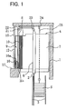
- Fig. 1 is a side view showing essential portions of an elevator apparatus according to a first embodiment of the present invention
- Fig. 2 is a plan view showing the apparatus in Fig. 1
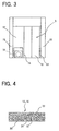
- Fig. 3 is a front view showing the hall entrance portion in fig. 1 as viewed from the elevator hall side.
- a pair of car guide rails 2 and a pair of weight guide rails 3 are installed in a hoistway 1.
- a car 4 is guided by the guide rails 2, and a counterweight 5 is guided by the weight guide rails 3, so that the car 4 and the counterweight 5 move up and down the hoistway 1.
- the car 4 has a car frame 6, a car cabin 7, and car doors 8.
- a hall entrance portion 9 is provided on each landing floor to face the hoistway 1.
- the hall entrance portion 9 is provided with hall doors 10, a door accommodating portion 11 (Fig. 2) in which the hall doors 10 are accommodated when the doors are opened, an entrance wall 12 disposed between the door accommodating portion 11 and the elevator hall, and a hall entrance post 13.
- the entrance wall 12 is provided with a inspection door 14, which can be opened and closed from the elevator hall side.
- a hall wall 15 is provided on each side of the hall entrance portion 9.
- a driving machine 16 for moving up and down the car 4 and the counterweight 5 is provided at the hall entrance portion 9 of the uppermost landing floor.
- the driving machine 16 is disposed in a space between the door accommodating portion 11 and the entrance wall 12.
- the driving machine 16 has a brake device 16a and a driving sheave 16b, and is installed on a hall floor 17 in such a direction where the brake device 16a is located on the inspection door 14 side.
- a first car side return pulley 21 and a first weight side return pulley 22 are provided at a ceiling portion of the hall entrance portion 9 of the uppermost landing floor, i.e. just above the driving machine 16.
- a second car side return pulley 23 and a second weight side return pulley 24 are provided at a ceiling portion of the hoistway 1.
- the car 4 and the counterweight 5 are suspended in the hoistway 1 by a rope 25, and moved up and down by the driving machine 16 through the rope 25.
- the intermediate portion of the rope 25 is wound around the driving sheave 16b of the driving machine 16, one end portion of the rope 25 is connected to the car 4, and the other end portion of the rope 25 is connected to the counterweight 5.
- a part of the rope 25 extending from the driving machine 16 to the car 4 is wound around the first and second car side return pulleys 21 and 23. Further, a part of the rope 25 extending from the driving machine 16 to the counterweight 5 is wound around the first and second weight side return pulleys 22 and 24.
- Each of the entrance wall 12 and the inspection door 14 is formed, for instance, of a fire-proof and sound-proof material having a sectional structure as shown in Fig. 4.
- a fire-proof and sound-proof material having a sandwich structure is used.
- Such a sandwich structure is formed by hardening a large number of nonflammable particles 31 with a nonflammable hardening material 32 and holding between two metal thin sheets 33.
- nonflammable particles 31 aluminum particles, ceramic balloons, silastic balloons (hollow volcanic ash from the Mt. Kirishima volcano), glass balloons, or mixtures thereof are used as the nonflammable particles 31.
- An inorganic adhesive for instance, is used as the nonflammable fixing material 32.
- the inspection door 14 is provided at the entrance wall 12, operating efficiency of maintenance/inspection operations, and of the operations for the driving machine 16 when the car 4 is stopped between floors can be improved. Further, in the first embodiment, since the operations for the driving machine 16 are performed mainly on the brake device 16a and the brake device 16a is disposed at the inspection door 14 side, operating efficiency of the operations for the driving machine 16 can further be improved.
- the driving machine 16 is disposed at the hall entrance portion 9 of the uppermost landing floor, the length of the rope 25 can be shortened as well as the layout of the rope 25 can be simplified.
- the entrance wall 12 and the inspection door 14, which face the elevator hall are formed of the fire-proof and sound-proof material, it is possible to prevent a flame from entering into the elevator hall side if the driving machine 16 fires accidentally. Further, it is possible to suppress the transmission of noise of the driving machine 16 to the elevator hall side.
- the driving machine 16 is disposed between the door accommodating portion 11 and the entrance wall 12, it is also possible that the driving machine 16 is disposed at any unoccupied space left, for instance, at the side of the door accommodating portion 11.
- the inspection door 14 is provided at the front surface of the entrance wall 12, but the inspection door 14 may be provided, for instance, at a side surface of the entrance wall 12 (i.e. a surface facing the hall entrance post 13 in Fig. 2).
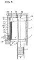
- Fig. 5 is a side view showing essential portions of an elevator apparatus according to a second embodiment of the present invention
- Fig. 6 is a front view showing the hall entrance portion in Fig. 5 as viewed from the elevator hall side
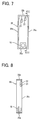
- Fig. 7 is a front view schematically showing the driving machine unit in Fig. 5
- Fig. 8 is a sectional view taken along the line VIII-VIII of Fig. 7.
- a driving machine unit frame 35 on which the driving machine 16, the first car side return pulley 21 and the first weight side return pulley 22 are mounted, is installed in a space between the door accommodating portion 11 (see Fig. 2) and the entrance wall 12 in the hall entrance portion 9 of the uppermost landing floor.
- the driving machine unit frame 35 is fixed to both of the hall floor 17 and the ceiling portion of the hall entrance portion 9.
- the driving machine unit frame 35 includes a driving machine mounting portion (a lower frame) 35a onto which the driving machine 16 is mounted, a return pulley mounting portion (an upper frame) 35b onto which the return pulleys 21 and 22 are mounted, and a pair of connecting portions (vertical posts) 35c, each connecting the driving machine mounting portion 35a to the return pulley mounting portion 35b.
- the return pulley mounting portion 35b maybe elongated to an upper space in the hoistway 1 to have all return pulleys 21 to 24 mounted thereon.
- Fig. 9 is a side view showing essential portions of an elevator apparatus according to a third embodiment of the present invention
- Fig. 10 is a plan view showing the apparatus in Fig. 9.
- a pair of car suspension sheaves 36 where the rope 25 is wound around are provided at a lower portion of the car frame 6.
- the part of the car 4 side of the rope 25 extends from the second car side return pulley 23 through the pair of car suspension sheaves 36 so that the end portion thereof is fixed in the upper space of the hoistway 1.
- the other constructions are the same as in the first embodiment, but the part of the counterweight 5 side of the rope 25 is arranged such that it extends front the second weight side return pulley 24 through a weight suspension sheave (not shown) provided on the upper portion of the counterweight 5 with the end portion thereof fixed in the upper space of the hoistway 1.
- the driving machine 16 since the driving machine 16 is disposed at the hall entrance portion 9, installation operations and maintenance/inspection operations for the driving machine 16 can be performed on the elevator hall side, thereby improving operating efficiency of installation operations and maintenance/inspection operations. Further, the operations for the driving machine 16 when the car 4 is stopped between floors can be easily carried out, and passengers can be rescued quickly.
- Fig. 11 is a side view showing essential portions of an elevator apparatus according to a fourth embodiment of the present invention.
- the driving machine 16 is disposed at the hall entrance portion 9 of a landing floor below the uppermost landing floor.
- the hall floor 17 on each landing floor located above the driving machine 16 is provided with a rope hole 17a for passing through the rope 25.
- the other constructions are the same as in the third embodiment.
- the driving machine 16 can be disposed at the hall entrance portion 9 of any hall stage other than the uppermost landing floor by passing the rope 25 through the rope hole 17a, thereby increasing the degree of freedom in design.
- Embodiment 5 Embodiment 5
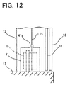
- Fig. 12 is a side view showing essential portions of an elevator apparatus according to a fifth embodiment of the present invention.
- the driving machine 16 is accommodated within a fire-resistive box 41 made of a nonflammable material.
- the fire-resistive box 41 is provided with a rope leading-out portion 41a for leading out the rope. That is, the driving machine 16 is covered by the fire-resistive box 41 of the non-flammable material with the exception of the opening of the rope leading-out portion 41a.
- the other constructions are the same as in the first embodiment.
- the driving machine 16 is disposed between an elevator hall and the hoistway 1, the driving machine 16 is accommodated within the fire-resistive box 41. Consequently, if the driving machine 16 fires accidentally, it is possible to prevent a flame from entering into the elevator hall side and the hoistway 1 side. Further, it is possible to suppress the transmission of noise of the driving machine 16 to the hall side.
- the elevator apparatus of a side opening door type using two doors is described, no limitation is put on the door type.
- the present invention can be applied to an elevator apparatus of center opening door type using two doors as shown in Figs. 13 and 14.
Landscapes
- Engineering & Computer Science (AREA)
- Civil Engineering (AREA)
- Mechanical Engineering (AREA)
- Structural Engineering (AREA)
- Elevator Door Apparatuses (AREA)
- Lift-Guide Devices, And Elevator Ropes And Cables (AREA)
- Types And Forms Of Lifts (AREA)
Abstract
Description
Claims (9)
- An elevator apparatus comprising:a hoistway (1);a car (4) moving up and down in said hoistway (1);a rope (25) for suspending said car (4) in said hoistway (1);a hall entrance portion (9) provided on each landing floor to face said hoistway (1), said hall entrance portion (9) having a hall door (10), a door accommodating portion (11) in which said hall door (10) is accommodated when said hall door (10) is opened, and an entrance wall (12) disposed between said door accommodating portion (11) and an elevator hall; anda driving machine (16) for moving up and down said car (4) through said rope (25);
characterized in that said driving machine (16) is disposed inside said entrance wall (12) of said hall entrance portion (9), and a plurality of return pulleys (21, 22, 23, 24) where said rope (25) is wound around are disposed above said car (4) and said driving machine (16). - The elevator apparatus as set forth in claim 1, wherein said driving machine (16) is disposed between said door accommodating portion (11) and said entrance wall (12).
- The elevator apparatus as set forth in claim 1, wherein a inspection door (14), which is opened and closed on the elevator hall side when said driving machine (16) is subjected to maintenance and inspection, is provided on said entrance wall (12).
- The elevator apparatus as set forth in claim 3, wherein said driving machine (16) has a brake device (16a), and is disposed so that said brake device (16a) is located on the inspection door (14) side.
- The elevator apparatus as set forth in claim 1, wherein said driving machine (16) is disposed at said hall entrance portion (9) of the uppermost landing floor.
- The elevator apparatus as set forth in claim 5, further comprising:a driving machine unit frame (35) including a driving machine mounting portion (35a) onto which said driving machine (16) is mounted, a return pulley mounting portion (35b) onto which at least one of said return pulleys (21, 22) are mounted, and connecting portions (35c) connecting said driving machine mounting portion (35a) to said return pulley mounting portion (35b), said driving machine unit frame (35) being provided at said hall entrance portion (9).
- The elevator apparatus as set forth in claim 1, wherein said entrance wall (12) is constructed of a fire-proof and sound-proof material.
- The elevator apparatus as set forth in claim 1, further comprising:a fire-resistive box (41) made of non-flammable material, having a rope leading-out portion (41a) for leading out said rope (25), and accommodating said driving machine (16) therein.
- The elevator apparatus as set forth in claim 1, wherein a plurality of car suspension sheaves (36) where said rope (25) is wound around are provided on a lower portion of said car (4).
Applications Claiming Priority (2)
| Application Number | Priority Date | Filing Date | Title |
|---|---|---|---|
| JP24285499A JP2001063935A (en) | 1999-08-30 | 1999-08-30 | Elevator equipment |
| JP24285499 | 1999-08-30 |
Publications (3)
| Publication Number | Publication Date |
|---|---|
| EP1081085A2 true EP1081085A2 (en) | 2001-03-07 |
| EP1081085A3 EP1081085A3 (en) | 2002-07-24 |
| EP1081085B1 EP1081085B1 (en) | 2003-10-15 |
Family
ID=17095269
Family Applications (1)
| Application Number | Title | Priority Date | Filing Date |
|---|---|---|---|
| EP20000114147 Expired - Lifetime EP1081085B1 (en) | 1999-08-30 | 2000-07-11 | Elevator without a machine room |
Country Status (5)
| Country | Link |
|---|---|
| EP (1) | EP1081085B1 (en) |
| JP (1) | JP2001063935A (en) |
| CN (1) | CN1120124C (en) |
| DE (1) | DE60005898T2 (en) |
| TW (1) | TW496851B (en) |
Cited By (3)
| Publication number | Priority date | Publication date | Assignee | Title |
|---|---|---|---|---|
| WO2004106206A2 (en) | 2003-05-27 | 2004-12-09 | Otis Elevator Company | Elevator device |
| ITUA20161927A1 (en) * | 2016-03-23 | 2017-09-23 | Finpac S P A | MACHINEROOMLESS LIFT SYSTEM WITH MOTOR UNIT ACCESSIBLE FROM THE OUTSIDE |
| CN113666225A (en) * | 2021-08-26 | 2021-11-19 | 日立电梯(中国)有限公司 | A machine room-less elevator structure |
Families Citing this family (8)
| Publication number | Priority date | Publication date | Assignee | Title |
|---|---|---|---|---|
| ITMI20012558A1 (en) * | 2001-12-04 | 2003-06-04 | L A Consulting S A S Di Sara F | LIFT WITH GUIDED CABIN IN A RUNNING ROOM, WITHOUT MACHINE ROOM |
| CN1592712A (en) * | 2002-12-04 | 2005-03-09 | 三菱电机株式会社 | Elevator device |
| CN101088901B (en) * | 2006-06-13 | 2012-05-02 | 上海三菱电梯有限公司 | Elevator device without machine room |
| JP5518892B2 (en) | 2008-12-05 | 2014-06-11 | オーチス エレベータ カンパニー | Elevator machine support |
| CN102239103B (en) | 2008-12-05 | 2015-11-25 | 奥的斯电梯公司 | Elevator device and installation method |
| EP2361211B1 (en) | 2008-12-05 | 2013-10-09 | Otis Elevator Company | Elevator system including control electronics supported on an elevator machine support |
| JP5649061B2 (en) * | 2011-04-11 | 2015-01-07 | 東芝エレベータ株式会社 | Elevator landing detection device |
| CN102774726A (en) * | 2012-07-10 | 2012-11-14 | 希姆斯电梯(中国)有限公司 | Mounting structure of asymmetrical lift car walls |
Family Cites Families (4)
| Publication number | Priority date | Publication date | Assignee | Title |
|---|---|---|---|---|
| FI95456C (en) * | 1994-05-04 | 1996-02-12 | Kone Oy | Arrangement of the elevator shaft wall opening and dashboard |
| FI100793B (en) * | 1995-06-22 | 1998-02-27 | Kone Oy | Traction sheave elevator |
| EP0867396A1 (en) * | 1997-03-24 | 1998-09-30 | Inventio Ag | Hydraulic elevator |
| EP1081086B1 (en) * | 1999-08-19 | 2005-10-12 | Inventio Ag | Liftarrangement with a drive unit positioned in the liftshaft |
-
1999
- 1999-08-30 JP JP24285499A patent/JP2001063935A/en not_active Withdrawn
-
2000
- 2000-06-21 TW TW89112150A patent/TW496851B/en not_active IP Right Cessation
- 2000-07-11 DE DE2000605898 patent/DE60005898T2/en not_active Expired - Fee Related
- 2000-07-11 EP EP20000114147 patent/EP1081085B1/en not_active Expired - Lifetime
- 2000-08-08 CN CN 00122766 patent/CN1120124C/en not_active Expired - Fee Related
Cited By (4)
| Publication number | Priority date | Publication date | Assignee | Title |
|---|---|---|---|---|
| WO2004106206A2 (en) | 2003-05-27 | 2004-12-09 | Otis Elevator Company | Elevator device |
| EP1633668A4 (en) * | 2003-05-27 | 2011-06-22 | Otis Elevator Co | Elevator device |
| ITUA20161927A1 (en) * | 2016-03-23 | 2017-09-23 | Finpac S P A | MACHINEROOMLESS LIFT SYSTEM WITH MOTOR UNIT ACCESSIBLE FROM THE OUTSIDE |
| CN113666225A (en) * | 2021-08-26 | 2021-11-19 | 日立电梯(中国)有限公司 | A machine room-less elevator structure |
Also Published As
| Publication number | Publication date |
|---|---|
| DE60005898T2 (en) | 2004-08-19 |
| CN1120124C (en) | 2003-09-03 |
| DE60005898D1 (en) | 2003-11-20 |
| EP1081085A3 (en) | 2002-07-24 |
| EP1081085B1 (en) | 2003-10-15 |
| JP2001063935A (en) | 2001-03-13 |
| TW496851B (en) | 2002-08-01 |
| CN1286209A (en) | 2001-03-07 |
Similar Documents
| Publication | Publication Date | Title |
|---|---|---|
| EP1016614B1 (en) | Controller for elevators | |
| JP2992219B2 (en) | Traction sheave elevator and hoisting device | |
| JP4771586B2 (en) | elevator | |
| CA2385569C (en) | Rope elevator | |
| FI98296C (en) | Drive lift and machine space for drive lift | |
| EP1471026A9 (en) | Elevator device | |
| EP1081085B1 (en) | Elevator without a machine room | |
| JPH11106159A (en) | Elevator | |
| CN100402402C (en) | elevator | |
| JPWO2003091141A1 (en) | Elevator equipment | |
| US20070175707A1 (en) | Elevator | |
| EP1602614A1 (en) | Elevator equipment | |
| KR100950991B1 (en) | Traction machine structure for an elevator and cage assembly | |
| JP3603606B2 (en) | Elevator equipment | |
| EP1057769B1 (en) | Elevator | |
| KR100941955B1 (en) | Traction machine structure for an elevator and cage assembly | |
| EP1741660A1 (en) | Elevator apparatus | |
| WO2005121007A1 (en) | Elevator apparatus | |
| JP2005145609A (en) | Elevator equipment | |
| JP2004292162A (en) | Elevator | |
| JPH05306083A (en) | Elevator equipment | |
| JP3399161B2 (en) | Elevator equipment | |
| KR100455502B1 (en) | Installation structure of elevator traction machine | |
| JP4037209B2 (en) | Elevator equipment | |
| JP7757236B2 (en) | elevator equipment |
Legal Events
| Date | Code | Title | Description |
|---|---|---|---|
| PUAI | Public reference made under article 153(3) epc to a published international application that has entered the european phase |
Free format text: ORIGINAL CODE: 0009012 |
|
| AK | Designated contracting states |
Kind code of ref document: A2 Designated state(s): AT BE CH CY DE DK ES FI FR GB GR IE IT LI LU MC NL PT SE |
|
| AX | Request for extension of the european patent |
Free format text: AL;LT;LV;MK;RO;SI |
|
| PUAL | Search report despatched |
Free format text: ORIGINAL CODE: 0009013 |
|
| AK | Designated contracting states |
Kind code of ref document: A3 Designated state(s): AT BE CH CY DE DK ES FI FR GB GR IE IT LI LU MC NL PT SE |
|
| AX | Request for extension of the european patent |
Free format text: AL;LT;LV;MK;RO;SI |
|
| RIC1 | Information provided on ipc code assigned before grant |
Free format text: 7B 66B 11/00 A, 7B 66B 13/30 B |
|
| 17P | Request for examination filed |
Effective date: 20020705 |
|
| GRAH | Despatch of communication of intention to grant a patent |
Free format text: ORIGINAL CODE: EPIDOS IGRA |
|
| AKX | Designation fees paid |
Designated state(s): DE FR GB NL |
|
| GRAS | Grant fee paid |
Free format text: ORIGINAL CODE: EPIDOSNIGR3 |
|
| GRAA | (expected) grant |
Free format text: ORIGINAL CODE: 0009210 |
|
| AK | Designated contracting states |
Kind code of ref document: B1 Designated state(s): DE FR GB NL |
|
| REG | Reference to a national code |
Ref country code: GB Ref legal event code: FG4D |
|
| REG | Reference to a national code |
Ref country code: IE Ref legal event code: FG4D |
|
| REF | Corresponds to: |
Ref document number: 60005898 Country of ref document: DE Date of ref document: 20031120 Kind code of ref document: P |
|
| REG | Reference to a national code |
Ref country code: GB Ref legal event code: 727 |
|
| ET | Fr: translation filed | ||
| REG | Reference to a national code |
Ref country code: GB Ref legal event code: 727A |
|
| PLBE | No opposition filed within time limit |
Free format text: ORIGINAL CODE: 0009261 |
|
| STAA | Information on the status of an ep patent application or granted ep patent |
Free format text: STATUS: NO OPPOSITION FILED WITHIN TIME LIMIT |
|
| 26N | No opposition filed |
Effective date: 20040716 |
|
| REG | Reference to a national code |
Ref country code: GB Ref legal event code: 727H |
|
| REG | Reference to a national code |
Ref country code: IE Ref legal event code: MM4A |
|
| PGFP | Annual fee paid to national office [announced via postgrant information from national office to epo] |
Ref country code: DE Payment date: 20070705 Year of fee payment: 8 |
|
| PGFP | Annual fee paid to national office [announced via postgrant information from national office to epo] |
Ref country code: GB Payment date: 20070711 Year of fee payment: 8 |
|
| PGFP | Annual fee paid to national office [announced via postgrant information from national office to epo] |
Ref country code: FR Payment date: 20070710 Year of fee payment: 8 |
|
| PGFP | Annual fee paid to national office [announced via postgrant information from national office to epo] |
Ref country code: NL Payment date: 20080715 Year of fee payment: 9 |
|
| GBPC | Gb: european patent ceased through non-payment of renewal fee |
Effective date: 20080711 |
|
| PG25 | Lapsed in a contracting state [announced via postgrant information from national office to epo] |
Ref country code: DE Free format text: LAPSE BECAUSE OF NON-PAYMENT OF DUE FEES Effective date: 20090203 |
|
| REG | Reference to a national code |
Ref country code: FR Ref legal event code: ST Effective date: 20090331 |
|
| PG25 | Lapsed in a contracting state [announced via postgrant information from national office to epo] |
Ref country code: GB Free format text: LAPSE BECAUSE OF NON-PAYMENT OF DUE FEES Effective date: 20080711 |
|
| PG25 | Lapsed in a contracting state [announced via postgrant information from national office to epo] |
Ref country code: FR Free format text: LAPSE BECAUSE OF NON-PAYMENT OF DUE FEES Effective date: 20080731 |
|
| NLV4 | Nl: lapsed or anulled due to non-payment of the annual fee |
Effective date: 20100201 |
|
| PG25 | Lapsed in a contracting state [announced via postgrant information from national office to epo] |
Ref country code: NL Free format text: LAPSE BECAUSE OF NON-PAYMENT OF DUE FEES Effective date: 20100201 |