EP1081023A1 - Structure avant de véhicule automobile et véhicule automobile équipé de cette structure - Google Patents
Structure avant de véhicule automobile et véhicule automobile équipé de cette structure Download PDFInfo
- Publication number
- EP1081023A1 EP1081023A1 EP00402387A EP00402387A EP1081023A1 EP 1081023 A1 EP1081023 A1 EP 1081023A1 EP 00402387 A EP00402387 A EP 00402387A EP 00402387 A EP00402387 A EP 00402387A EP 1081023 A1 EP1081023 A1 EP 1081023A1
- Authority
- EP
- European Patent Office
- Prior art keywords
- bar
- cradle
- powertrain
- vehicle
- front structure
- Prior art date
- Legal status (The legal status is an assumption and is not a legal conclusion. Google has not performed a legal analysis and makes no representation as to the accuracy of the status listed.)
- Granted
Links
Images


Classifications
-
- B—PERFORMING OPERATIONS; TRANSPORTING
- B60—VEHICLES IN GENERAL
- B60K—ARRANGEMENT OR MOUNTING OF PROPULSION UNITS OR OF TRANSMISSIONS IN VEHICLES; ARRANGEMENT OR MOUNTING OF PLURAL DIVERSE PRIME-MOVERS IN VEHICLES; AUXILIARY DRIVES FOR VEHICLES; INSTRUMENTATION OR DASHBOARDS FOR VEHICLES; ARRANGEMENTS IN CONNECTION WITH COOLING, AIR INTAKE, GAS EXHAUST OR FUEL SUPPLY OF PROPULSION UNITS IN VEHICLES
- B60K5/00—Arrangement or mounting of internal-combustion or jet-propulsion units
- B60K5/04—Arrangement or mounting of internal-combustion or jet-propulsion units with the engine main axis, e.g. crankshaft axis, transversely to the longitudinal centre line of the vehicle
-
- B—PERFORMING OPERATIONS; TRANSPORTING
- B60—VEHICLES IN GENERAL
- B60K—ARRANGEMENT OR MOUNTING OF PROPULSION UNITS OR OF TRANSMISSIONS IN VEHICLES; ARRANGEMENT OR MOUNTING OF PLURAL DIVERSE PRIME-MOVERS IN VEHICLES; AUXILIARY DRIVES FOR VEHICLES; INSTRUMENTATION OR DASHBOARDS FOR VEHICLES; ARRANGEMENTS IN CONNECTION WITH COOLING, AIR INTAKE, GAS EXHAUST OR FUEL SUPPLY OF PROPULSION UNITS IN VEHICLES
- B60K17/00—Arrangement or mounting of transmissions in vehicles
-
- B—PERFORMING OPERATIONS; TRANSPORTING
- B60—VEHICLES IN GENERAL
- B60K—ARRANGEMENT OR MOUNTING OF PROPULSION UNITS OR OF TRANSMISSIONS IN VEHICLES; ARRANGEMENT OR MOUNTING OF PLURAL DIVERSE PRIME-MOVERS IN VEHICLES; AUXILIARY DRIVES FOR VEHICLES; INSTRUMENTATION OR DASHBOARDS FOR VEHICLES; ARRANGEMENTS IN CONNECTION WITH COOLING, AIR INTAKE, GAS EXHAUST OR FUEL SUPPLY OF PROPULSION UNITS IN VEHICLES
- B60K5/00—Arrangement or mounting of internal-combustion or jet-propulsion units
- B60K5/12—Arrangement of engine supports
- B60K5/1208—Resilient supports
- B60K5/1216—Resilient supports characterised by the location of the supports relative to the motor or to each other
-
- B—PERFORMING OPERATIONS; TRANSPORTING
- B62—LAND VEHICLES FOR TRAVELLING OTHERWISE THAN ON RAILS
- B62D—MOTOR VEHICLES; TRAILERS
- B62D21/00—Understructures, i.e. chassis frame on which a vehicle body may be mounted
- B62D21/11—Understructures, i.e. chassis frame on which a vehicle body may be mounted with resilient means for suspension, e.g. of wheels or engine; sub-frames for mounting engine or suspensions
-
- B—PERFORMING OPERATIONS; TRANSPORTING
- B62—LAND VEHICLES FOR TRAVELLING OTHERWISE THAN ON RAILS
- B62D—MOTOR VEHICLES; TRAILERS
- B62D21/00—Understructures, i.e. chassis frame on which a vehicle body may be mounted
- B62D21/15—Understructures, i.e. chassis frame on which a vehicle body may be mounted having impact absorbing means, e.g. a frame designed to permanently or temporarily change shape or dimension upon impact with another body
- B62D21/152—Front or rear frames
-
- B—PERFORMING OPERATIONS; TRANSPORTING
- B60—VEHICLES IN GENERAL
- B60G—VEHICLE SUSPENSION ARRANGEMENTS
- B60G2204/00—Indexing codes related to suspensions per se or to auxiliary parts
- B60G2204/10—Mounting of suspension elements
- B60G2204/15—Mounting of subframes
-
- B—PERFORMING OPERATIONS; TRANSPORTING
- B60—VEHICLES IN GENERAL
- B60G—VEHICLE SUSPENSION ARRANGEMENTS
- B60G2204/00—Indexing codes related to suspensions per se or to auxiliary parts
- B60G2204/10—Mounting of suspension elements
- B60G2204/16—Mounting of vehicle body on chassis
Definitions
- the present invention relates to a structure before front wheel drive vehicle and one vehicle equipped with this structure.
- a vehicle front structure automobile comprising a stretcher made up of two spars symmetrical with respect to the median plane of the vehicle and connected by a short cradle, the ends front side members being curved and raised to support the fasteners of the powertrain.
- Such a structure has many drawbacks, especially during a front impact.
- the powertrain then rises above the cradle, because it is short and therefore does not block the movement of the powertrain. This causes the intrusion of parts into the passenger compartment of the vehicle, which is dangerous for passengers.
- the object of the invention is to eliminate these drawbacks by proposing a front structure of a motor vehicle which has a high shock absorption capacity, which preserves the integrity of the passenger compartment vehicle, in the event of a frontal impact, limiting the risk of tilting the powertrain, and which allows the use of conventional powertrain, without modification.
- the invention relates to a structure before motor vehicle comprising a stretcher secured to the passenger compartment of the vehicle and consisting of two side members symmetrical with respect to the median plane of the vehicle and connected by a short cradle, the front ends of the longitudinal members being curved and raised and supporting the fasteners for the powertrain, characterized in that it comprises a bar extending longitudinally, substantially parallel to the side members, which is fixed on the powertrain, with its face front located between the front face of the side members and the face front of the powertrain and its rear face vis-à-vis the cradle, this bar being substantially undeformable longitudinally, so that in case front impact on the vehicle, the side members deform and the bar comes into contact, by its rear face, on the cradle and substantially blocks any further movement balance of the powertrain.
- this bar has on its rear face a nose portion, intended to come into contact with the cradle.
- the bar advantageously has a slightly curved profile for facilitate its introduction to the powertrain, before mounting on it.
- the part of the cradle opposite the bar is advantageously reinforced, to avoid too much deterioration of the cradle in the event of an impact, and transmit to the latter part of the shock energy.
- the attachments of the powertrain are attached to the front ends of the side members by through elastic shims.
- this bar includes fixing means on the gearbox and possibly centering pins on the motor.
- the invention also relates to a vehicle automobile equipped with a front structure conforming to one any of the features mentioned above.
- Figure 1 is a schematic side elevation view and in section of the front structure of the invention according to the line I-I of figure 2.
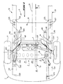
- Figure 2 is a schematic top view of the front structure of the invention.
- Figure 3 is a schematic perspective view along arrow III-III in Figure 1.
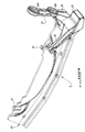
- Figure 4 is a perspective view of the bar of the front structure according to the invention.
- Figure 5 is a partial schematic view and lateral elevation of the front structure of the invention, showing the path of the forces in the event of an impact.
- Figure 6 is a partial schematic view of above the front structure of the invention, showing also the path of the forces in the event of an impact.
- Figure 7 is a partial schematic view in lateral elevation of the front structure of the invention, after a shock before.
- Figure 8 is a partial schematic view from above of the front structure of the invention, after a shock before.
- the front structure of the invention is mounted on a motor vehicle 1 which includes a cover 10, a bumper before 11 and one wing before 12.
- the vehicle 1 also includes a powerplant 2, consisting of a motor 20 and a box of speeds 21.
- the motor 20 is connected by a transmission 3 to wheel support bearings (not shown) 4.
- the front structure also includes a stretcher 5 which consists of two beams 50 and 51 symmetrical by relative to the median plane 13 of vehicle 1 and connected by a short cradle 52.
- Each of the side members has a curved front end and raised, composed of an element 500, 510 inclined towards the hood 10 of the vehicle and a straight portion 510, 511 which extends the inclined element and which is substantially parallel to the rest of the beam 50, 51.
- each beam goes under the carcass of the passenger compartment of the vehicle.
- the powertrain is attached to the front end spars 50 and 51 and more particularly on the straight portions 501 and 511.
- the motor 20 comprises, on the side of the right spar 50, a fixing clip 200 which is fixed by via an elastic block 201 on an element support 502 fixed on the portion 501 of the beam 50.
- the gearbox 21 has, on the side of the left side member 51, a fastener 210 which is connected to the portion 511 of the left spar 51 via a support piece 211, commonly known as a chair structure, and an elastic wedge 212.
- This support piece 211 is here made necessary, from the fact that the gearbox 21 is located lower than the motor 20.
- the powertrain 2 extends transversely with respect to the vehicle along axis 14, and therefore perpendicular to the median plane 13 of the vehicle, being fixed in its upper part to both side rails 50 and 51.
- the cradle 52 comprises, towards the front of the vehicle and on each of its longitudinal sides, a piece 520, 521 commonly known as the cradle horn.
- the cradle 52 has two extensions 524, 525 which are intended to be fixed under the beam 50, 51 by any appropriate means 526, 527.
- the suspension comprises two suspension triangles 60, 61 which are, by one of their ends 600, 610, fixed to cradle 52 by any suitable means 601, 611 and, by their opposite end 602, 612, are articulated by relative to a wheel 4.
- the front structure according to the invention comprises a steering rack 7 which is also supported by cradle 52.
- the front structure according to the invention also comprises a bar 8 which extends longitudinally, substantially parallel to the longitudinal members 50 and 51.
- Figure 3 illustrates the respective positions of the motor 20, of the gearbox 21, cradle 52 and bar 8.
- Figure 4 illustrates more precisely this bar 8, the left part of the drawing corresponding to the part of the bar 8 located at the front of the vehicle when the bar is attached to the powertrain 2 and the right part of this figure 4 illustrating the part of the bar 8 located towards the rear of the vehicle, after mounting.
- This bar 8 is relatively thin so as not to increase the weight of the vehicle too much.
- the rear face 81 of the beam 8 has a part 82 forming a nose which is designed to be particularly resistant. It is indeed this part 82 which is likely to come into contact with the cradle in the event of front impact, as will be described later.
- Figures 3 and 4 show that the bar 8 has, in this example, a slightly curved profile. For some people types of powertrain, this particular profile facilitates the introduction of the bar 8 under the powertrain 2.
- the bar 8 is positioned on the motor 20 notably by means of two centering pins 83, 84 which are located on the upper part of the bar 8 in the mounted position of this bar and which fit into holes (not shown) provided in the motor housing 20.
- the fixing of the bar 8 on the powertrain 2 is here carried out by means of flanges of fixing 85, 86 which have holes 850, 860, 861 intended to receive fixing means (not shown) on the gearbox 21.
- Figures 1 to 3 show that the dimensions of the bar 8 and its positioning relative to the side members 50 and 51 and to the powertrain 2 are chosen in such a way so that the front face 80 of the bar 8 is set back towards the rear of the vehicle with respect to the front faces 503, 513 of the side members 50, 51, this front face 80 being, on the other hand, located in front of the front face 220 of the powertrain 2.
- the front face of the bar 8 is located, in a longitudinal direction, between the front face of side members and the front face of the powertrain.
- the nose 82 of the bar 8 is offset towards the front relative to the cradle 52 and more precisely by compared to its front face 528.
- a free space is provided between the nose 82 and the front face 528 of the cradle 52.
- FIGS 1 to 3 show that reinforcing means 529 are fixed on the front face 528 of the cradle 52, in look of the nose 82 of the bar 8. These means of reinforcement may in particular take the form of a metal angle.
- the bar 8 can be adapted on all types of conventional powertrain, without that it is necessary to modify them.
- the profile of the helm 8 is simply adapted to the shape of the powertrain concerned.
- FIGS. 5 and 6 are however illustrated, by means of arrows, the paths of the forces during a front impact. This will be explained in more detail, with reference Figures 7 and 8 which illustrate the relative position of the various elements shown in FIGS. 5 and 6, after a front shock.
- the shock of the front structure according to the invention on the wall 9 produces forces in the longitudinal members 50 and 51 which propagate longitudinally, according to these side rails (arrows F1).
- Figures 7 and 8 show part 501, 511 of the spar 50, 51 with a front zone 504, 514 distorted towards the rear of the vehicle.
- the obstacle on which the shock occurs here the barrier 90, comes into contact with the front face 80 of bar 8.
- the latter is then also subjected to longitudinal forces, as illustrated Figures 5 and 6 (arrows F2).
- the nose 82 of the bar 8 then comes into contact with the front face 528 of the cradle 52 and more precisely with the reinforcement means 529 fixed on this front face.
- the bar 8 When the bar 8 comes into contact with the cradle 52, it substantially blocks any further movement of balance of the powertrain. Indeed, it acts like a spacer, between barrier 90 and the cradle 52.
- Bar 8 retains this spacer function since it is designed to be practically undeformable in the longitudinal direction.
- this bar 8 limits considerably the group's pendulum movement motor-propellant, which avoids any risk of intrusion of the powertrain in the passenger compartment of the vehicle, front impact.
- the bar 8 makes it possible to resume substantially all the efforts to which the powertrain would be submitted in the absence of this bar and this, without that the motor 20 and the gearbox 21 are reinforced. This therefore allows the use of standard engine and gearbox.
- bar 8 makes it possible to check the path of the forces during a front impact on the vehicle and also to balance the forces between the front ends of the side members and the cradle.
Abstract
Description
Claims (7)
- Structure avant de véhicule automobile comprenant un brancard (5) solidaire de l'habitacle du véhicule et constitué de deux longerons (50, 51) symétriques par rapport au plan médian (13) du véhicule et reliés par un berceau (52) court, les extrémités avant des longerons étant courbées et relevées et supportant les attaches de fixation (200, 211) du groupe moto-propulseur (2), caractérisée en ce qu'elle comprend une barre (8) s'étendant longitudinalement, sensiblement parallèle aux longerons (50, 51), qui est fixée sur le groupe moto-propulseur (2), avec sa face avant (80) située entre la face avant (503, 513) des longerons (50, 51) et la face avant (200) du groupe moto-propulseur (2) et sa face arrière (81) en vis-à-vis du berceau (52), cette barre (8) étant sensiblement indéformable longitudinalement, de telle sorte qu'en cas de choc avant sur le véhicule, les longerons (50, 51) se déforment et la barre (8) vient en contact, par sa face arrière, sur le berceau (52) et bloque sensiblement tout mouvement ultérieur de balancier du groupe moto-propulseur (2).
- Structure avant selon la revendication 1, caractérisée en ce que ladite barre (8) comporte sur sa face arrière (81), une partie formant nez (82) qui est destinée à venir en contact avec le berceau.
- Structure avant selon la revendication 1 ou 2, caractérisée en ce que ladite barre (8) présente un profil légèrement courbé pour faciliter son introduction sous le groupe moto-propulseur avant son montage sur celui-ci.
- Structure avant selon l'une des revendications 1 à 3, caractérisée en ce que la partie du berceau en vis-à-vis de la barre (8) est renforcée, afin de transmettre une partie de l'énergie aux longerons (50, 51) par l'intermédiaire du berceau.
- Structure avant selon l'une des revendications 1 à 4, caractérisée en ce que les attaches du groupe moto-propulseur (2) sont fixées sur les extrémités avant des longerons (50, 51) par l'intermédiaire de cales élastiques (201, 211).
- Structure avant selon l'une des revendications 1 à 5, caractérisé en ce que ladite barre (8) comporte des moyens de fixation (85, 86) sur la boíte de vitesses et des pions de centrage (83, 84) sur le moteur (20).
- Véhicule automobile équipé d'une structure avant selon l'une quelconque des revendications précédentes.
Applications Claiming Priority (2)
| Application Number | Priority Date | Filing Date | Title |
|---|---|---|---|
| FR9911019A FR2798109B1 (fr) | 1999-09-02 | 1999-09-02 | Structure avant de vehicule automobile et vehicule automobile equipe de cette structure |
| FR9911019 | 1999-09-02 |
Publications (2)
| Publication Number | Publication Date |
|---|---|
| EP1081023A1 true EP1081023A1 (fr) | 2001-03-07 |
| EP1081023B1 EP1081023B1 (fr) | 2003-07-23 |
Family
ID=9549498
Family Applications (1)
| Application Number | Title | Priority Date | Filing Date |
|---|---|---|---|
| EP00402387A Expired - Lifetime EP1081023B1 (fr) | 1999-09-02 | 2000-08-29 | Structure avant de véhicule automobile et véhicule automobile équipé de cette structure |
Country Status (5)
| Country | Link |
|---|---|
| EP (1) | EP1081023B1 (fr) |
| AT (1) | ATE245554T1 (fr) |
| DE (1) | DE60003986T2 (fr) |
| ES (1) | ES2202019T3 (fr) |
| FR (1) | FR2798109B1 (fr) |
Cited By (10)
| Publication number | Priority date | Publication date | Assignee | Title |
|---|---|---|---|---|
| FR2895352A1 (fr) * | 2005-12-22 | 2007-06-29 | Renault Sas | Structure avant de vehicule automobile et vehicule correspondant |
| FR2899553A1 (fr) * | 2006-04-07 | 2007-10-12 | Renault Sas | Berceau de structure avant de vehicule automobile |
| WO2009007565A1 (fr) * | 2007-07-09 | 2009-01-15 | Renault S.A.S | Agencement filtrant economique pour la fixation d'un mini berceau |
| FR2965531A1 (fr) * | 2010-09-30 | 2012-04-06 | Peugeot Citroen Automobiles Sa | Vehicule automobile comportant un impacteur de choc pour groupe motopropulseur actif lors d'un choc frontal |
| FR2966418A1 (fr) * | 2010-10-25 | 2012-04-27 | Renault Sa | Agencement pour la liaison entre un berceau et les longerons |
| FR2967952A1 (fr) * | 2010-11-25 | 2012-06-01 | Peugeot Citroen Automobiles Sa | Vehicule automobile equipe d'un dispositif anti-rotation du moteur transversal en cas de choc frontal |
| GB2490019A (en) * | 2011-04-16 | 2012-10-17 | Gm Global Tech Operations Inc | Vehicle body support structure |
| US9676415B2 (en) * | 2015-03-13 | 2017-06-13 | GM Global Technology Operations LLC | Rear drive module assembly and system for mounting to a vehicle |
| US20220169114A1 (en) * | 2015-08-23 | 2022-06-02 | Arctic Cat Inc. | Off road vehicle |
| US11787279B2 (en) | 2015-08-23 | 2023-10-17 | Arctic Cat Inc. | Off-road recreational vehicle |
Families Citing this family (2)
| Publication number | Priority date | Publication date | Assignee | Title |
|---|---|---|---|---|
| FR2832686B1 (fr) | 2001-11-26 | 2004-01-30 | Renault | Structure avant de vehicule automobile en berceau destinee a relier les longerons de la structure de caisse |
| FR3107689B1 (fr) * | 2020-02-27 | 2023-05-26 | Psa Automobiles Sa | Véhicule avec structure montrant une troisième voie d’effort entre le berceau et un brancard avant |
Citations (1)
| Publication number | Priority date | Publication date | Assignee | Title |
|---|---|---|---|---|
| US5477938A (en) * | 1990-10-08 | 1995-12-26 | Mazda Motor Corporation | Power plant supporting structure of automotive vehicle |
-
1999
- 1999-09-02 FR FR9911019A patent/FR2798109B1/fr not_active Expired - Fee Related
-
2000
- 2000-08-29 EP EP00402387A patent/EP1081023B1/fr not_active Expired - Lifetime
- 2000-08-29 DE DE60003986T patent/DE60003986T2/de not_active Expired - Lifetime
- 2000-08-29 AT AT00402387T patent/ATE245554T1/de not_active IP Right Cessation
- 2000-08-29 ES ES00402387T patent/ES2202019T3/es not_active Expired - Lifetime
Patent Citations (1)
| Publication number | Priority date | Publication date | Assignee | Title |
|---|---|---|---|---|
| US5477938A (en) * | 1990-10-08 | 1995-12-26 | Mazda Motor Corporation | Power plant supporting structure of automotive vehicle |
Cited By (17)
| Publication number | Priority date | Publication date | Assignee | Title |
|---|---|---|---|---|
| FR2895352A1 (fr) * | 2005-12-22 | 2007-06-29 | Renault Sas | Structure avant de vehicule automobile et vehicule correspondant |
| FR2899553A1 (fr) * | 2006-04-07 | 2007-10-12 | Renault Sas | Berceau de structure avant de vehicule automobile |
| WO2007116167A1 (fr) * | 2006-04-07 | 2007-10-18 | Renault S.A.S | Berceau de structure avant de vehicule automobile |
| WO2009007565A1 (fr) * | 2007-07-09 | 2009-01-15 | Renault S.A.S | Agencement filtrant economique pour la fixation d'un mini berceau |
| FR2918629A1 (fr) * | 2007-07-09 | 2009-01-16 | Renault Sas | Agencement filtrant economique pour la fixation d'un mini berceau |
| FR2965531A1 (fr) * | 2010-09-30 | 2012-04-06 | Peugeot Citroen Automobiles Sa | Vehicule automobile comportant un impacteur de choc pour groupe motopropulseur actif lors d'un choc frontal |
| RU2576310C2 (ru) * | 2010-10-25 | 2016-02-27 | Рено С.А.С. | Устройство для соединения подрамника с лонжеронами |
| WO2012055760A1 (fr) * | 2010-10-25 | 2012-05-03 | Renault S.A.S. | Agencement pour la liaison entre un berceau et les longerons |
| CN103282263A (zh) * | 2010-10-25 | 2013-09-04 | 雷诺股份公司 | 用于将托架与侧梁连接在一起的安排 |
| FR2966418A1 (fr) * | 2010-10-25 | 2012-04-27 | Renault Sa | Agencement pour la liaison entre un berceau et les longerons |
| FR2967952A1 (fr) * | 2010-11-25 | 2012-06-01 | Peugeot Citroen Automobiles Sa | Vehicule automobile equipe d'un dispositif anti-rotation du moteur transversal en cas de choc frontal |
| GB2490019A (en) * | 2011-04-16 | 2012-10-17 | Gm Global Tech Operations Inc | Vehicle body support structure |
| US8590663B2 (en) | 2011-04-16 | 2013-11-26 | GM Global Technology Operations LLC | Motor vehicle body |
| US9676415B2 (en) * | 2015-03-13 | 2017-06-13 | GM Global Technology Operations LLC | Rear drive module assembly and system for mounting to a vehicle |
| US20220169114A1 (en) * | 2015-08-23 | 2022-06-02 | Arctic Cat Inc. | Off road vehicle |
| US11766932B2 (en) * | 2015-08-23 | 2023-09-26 | Arctic Cat Inc. | Off road vehicle |
| US11787279B2 (en) | 2015-08-23 | 2023-10-17 | Arctic Cat Inc. | Off-road recreational vehicle |
Also Published As
| Publication number | Publication date |
|---|---|
| FR2798109A1 (fr) | 2001-03-09 |
| EP1081023B1 (fr) | 2003-07-23 |
| FR2798109B1 (fr) | 2001-12-07 |
| ES2202019T3 (es) | 2004-04-01 |
| ATE245554T1 (de) | 2003-08-15 |
| DE60003986T2 (de) | 2004-05-27 |
| DE60003986D1 (de) | 2003-08-28 |
Similar Documents
| Publication | Publication Date | Title |
|---|---|---|
| EP1874613B1 (fr) | Plancher arriere de vehicule automobile | |
| EP1081023B1 (fr) | Structure avant de véhicule automobile et véhicule automobile équipé de cette structure | |
| EP2930067B1 (fr) | Poutre de pare-chocs de véhicule, ensemble pare-chocs et véhicule associés | |
| FR3105153A1 (fr) | Structure de partie arriere de caisse de vehicule automobile equipee de longerons et longeronnets | |
| FR2951700A1 (fr) | Mecanisme de filtration des vibrations subies par un equipement d'un appareil volant en mouvement, un giravion notamment | |
| EP1419936A1 (fr) | Appui bas pour chocs piéton de véhicule automobile et pare-chocs de véhicule automobile muni d'un tel appui bas | |
| FR3078047A1 (fr) | Vehicule comprenant au moins un deviateur associe a un absorbeur pour repondre a un choc frontal de faible recouvrement | |
| EP1693283B1 (fr) | Structure avant de véhicule automobile | |
| EP0989007A1 (fr) | Dispositif formant renfort et porte pour véhicule automobile | |
| FR2676407A1 (fr) | Agencement d'une partie avant de vehicule automobile deformable en cas de choc frontal du vehicule. | |
| WO2016166432A1 (fr) | Ensemble de train arriere roulant integrant un moteur semi-porteur pour vehicule automobile | |
| FR3092309A1 (fr) | Vehicule electrique avec structure avant renforcee pour devier en cas de choc frontal a faible recouvrement | |
| EP4021781B1 (fr) | Vehicule hybride ou electrique avec dispositif de renforcement de sa structure de bas de caisse | |
| FR2552718A1 (fr) | Suspension pour automobiles et nouveau type de vehicule equipe d'une telle suspension | |
| EP1024037B1 (fr) | Train arrière de suspension pour véhicule automobile | |
| EP3898304B1 (fr) | Véhicule automobile comprenant un support de moteur et un châssis | |
| EP0659631B1 (fr) | Structure avant de véhicule automobile et véhicule équipé de cette structure | |
| FR2977559A1 (fr) | Vehicule automobile a deux roues et a structure porteuse et protectrice | |
| EP1542897A1 (fr) | Vehicule automobile | |
| FR2789031A1 (fr) | Dispositif de protection contre un choc frontal applique a la partie avant d'un vehicule automobile | |
| EP1937537B1 (fr) | Structure avant du vehicule automobile adaptee pour empecher l'intrusion d'une roue dans l'habitacle en cas de choc frontal | |
| EP4001060B1 (fr) | Structure avant de vehicule automobile a gestion de choc frontal de faible recouvrement | |
| FR2560853A1 (fr) | Chassis d'engin volant du type leger | |
| FR2882327A1 (fr) | Structure avant de vehicule automobile | |
| EP4110683A1 (fr) | Véhicule avec structure montrant une troisième voie d'effort entre le berceau et un brancard avant |
Legal Events
| Date | Code | Title | Description |
|---|---|---|---|
| PUAI | Public reference made under article 153(3) epc to a published international application that has entered the european phase |
Free format text: ORIGINAL CODE: 0009012 |
|
| AK | Designated contracting states |
Kind code of ref document: A1 Designated state(s): AT BE CH CY DE DK ES FI FR GB GR IE IT LI LU MC NL PT SE |
|
| AX | Request for extension of the european patent |
Free format text: AL;LT;LV;MK;RO;SI |
|
| 17P | Request for examination filed |
Effective date: 20010830 |
|
| AKX | Designation fees paid |
Free format text: AT BE CH CY DE DK ES FI FR GB GR IE IT LI LU MC NL PT SE |
|
| GRAH | Despatch of communication of intention to grant a patent |
Free format text: ORIGINAL CODE: EPIDOS IGRA |
|
| GRAH | Despatch of communication of intention to grant a patent |
Free format text: ORIGINAL CODE: EPIDOS IGRA |
|
| GRAA | (expected) grant |
Free format text: ORIGINAL CODE: 0009210 |
|
| AK | Designated contracting states |
Designated state(s): AT BE CH CY DE DK ES FI FR GB GR IE IT LI LU MC NL PT SE |
|
| PG25 | Lapsed in a contracting state [announced via postgrant information from national office to epo] |
Ref country code: FI Free format text: LAPSE BECAUSE OF FAILURE TO SUBMIT A TRANSLATION OF THE DESCRIPTION OR TO PAY THE FEE WITHIN THE PRESCRIBED TIME-LIMIT Effective date: 20030723 Ref country code: IE Free format text: LAPSE BECAUSE OF FAILURE TO SUBMIT A TRANSLATION OF THE DESCRIPTION OR TO PAY THE FEE WITHIN THE PRESCRIBED TIME-LIMIT Effective date: 20030723 Ref country code: NL Free format text: LAPSE BECAUSE OF FAILURE TO SUBMIT A TRANSLATION OF THE DESCRIPTION OR TO PAY THE FEE WITHIN THE PRESCRIBED TIME-LIMIT Effective date: 20030723 Ref country code: AT Free format text: LAPSE BECAUSE OF FAILURE TO SUBMIT A TRANSLATION OF THE DESCRIPTION OR TO PAY THE FEE WITHIN THE PRESCRIBED TIME-LIMIT Effective date: 20030723 |
|
| REG | Reference to a national code |
Ref country code: GB Ref legal event code: FG4D Free format text: NOT ENGLISH |
|
| REG | Reference to a national code |
Ref country code: CH Ref legal event code: EP |
|
| REG | Reference to a national code |
Ref country code: IE Ref legal event code: FG4D Free format text: FRENCH |
|
| REF | Corresponds to: |
Ref document number: 60003986 Country of ref document: DE Date of ref document: 20030828 Kind code of ref document: P |
|
| PG25 | Lapsed in a contracting state [announced via postgrant information from national office to epo] |
Ref country code: LU Free format text: LAPSE BECAUSE OF NON-PAYMENT OF DUE FEES Effective date: 20030829 Ref country code: CY Free format text: LAPSE BECAUSE OF FAILURE TO SUBMIT A TRANSLATION OF THE DESCRIPTION OR TO PAY THE FEE WITHIN THE PRESCRIBED TIME-LIMIT Effective date: 20030829 |
|
| PG25 | Lapsed in a contracting state [announced via postgrant information from national office to epo] |
Ref country code: BE Free format text: LAPSE BECAUSE OF NON-PAYMENT OF DUE FEES Effective date: 20030831 Ref country code: MC Free format text: LAPSE BECAUSE OF NON-PAYMENT OF DUE FEES Effective date: 20030831 |
|
| PG25 | Lapsed in a contracting state [announced via postgrant information from national office to epo] |
Ref country code: DK Free format text: LAPSE BECAUSE OF FAILURE TO SUBMIT A TRANSLATION OF THE DESCRIPTION OR TO PAY THE FEE WITHIN THE PRESCRIBED TIME-LIMIT Effective date: 20031023 Ref country code: GR Free format text: LAPSE BECAUSE OF FAILURE TO SUBMIT A TRANSLATION OF THE DESCRIPTION OR TO PAY THE FEE WITHIN THE PRESCRIBED TIME-LIMIT Effective date: 20031023 Ref country code: SE Free format text: LAPSE BECAUSE OF FAILURE TO SUBMIT A TRANSLATION OF THE DESCRIPTION OR TO PAY THE FEE WITHIN THE PRESCRIBED TIME-LIMIT Effective date: 20031023 |
|
| NLV1 | Nl: lapsed or annulled due to failure to fulfill the requirements of art. 29p and 29m of the patents act | ||
| GBT | Gb: translation of ep patent filed (gb section 77(6)(a)/1977) |
Effective date: 20031110 |
|
| PG25 | Lapsed in a contracting state [announced via postgrant information from national office to epo] |
Ref country code: PT Free format text: LAPSE BECAUSE OF FAILURE TO SUBMIT A TRANSLATION OF THE DESCRIPTION OR TO PAY THE FEE WITHIN THE PRESCRIBED TIME-LIMIT Effective date: 20031223 |
|
| REG | Reference to a national code |
Ref country code: IE Ref legal event code: FD4D |
|
| BERE | Be: lapsed |
Owner name: S.A. *PEUGEOT CITROEN AUTOMOBILES Effective date: 20030831 |
|
| REG | Reference to a national code |
Ref country code: ES Ref legal event code: FG2A Ref document number: 2202019 Country of ref document: ES Kind code of ref document: T3 |
|
| PLBE | No opposition filed within time limit |
Free format text: ORIGINAL CODE: 0009261 |
|
| STAA | Information on the status of an ep patent application or granted ep patent |
Free format text: STATUS: NO OPPOSITION FILED WITHIN TIME LIMIT |
|
| 26N | No opposition filed |
Effective date: 20040426 |
|
| PG25 | Lapsed in a contracting state [announced via postgrant information from national office to epo] |
Ref country code: CH Free format text: LAPSE BECAUSE OF NON-PAYMENT OF DUE FEES Effective date: 20040831 Ref country code: LI Free format text: LAPSE BECAUSE OF NON-PAYMENT OF DUE FEES Effective date: 20040831 |
|
| REG | Reference to a national code |
Ref country code: CH Ref legal event code: PL |
|
| REG | Reference to a national code |
Ref country code: GB Ref legal event code: 746 Effective date: 20070119 |
|
| PGFP | Annual fee paid to national office [announced via postgrant information from national office to epo] |
Ref country code: IT Payment date: 20080812 Year of fee payment: 9 |
|
| PGFP | Annual fee paid to national office [announced via postgrant information from national office to epo] |
Ref country code: GB Payment date: 20080729 Year of fee payment: 9 |
|
| GBPC | Gb: european patent ceased through non-payment of renewal fee |
Effective date: 20090829 |
|
| PG25 | Lapsed in a contracting state [announced via postgrant information from national office to epo] |
Ref country code: GB Free format text: LAPSE BECAUSE OF NON-PAYMENT OF DUE FEES Effective date: 20090829 |
|
| REG | Reference to a national code |
Ref country code: ES Ref legal event code: GC2A Effective date: 20110316 |
|
| PG25 | Lapsed in a contracting state [announced via postgrant information from national office to epo] |
Ref country code: IT Free format text: LAPSE BECAUSE OF NON-PAYMENT OF DUE FEES Effective date: 20090829 |
|
| PGFP | Annual fee paid to national office [announced via postgrant information from national office to epo] |
Ref country code: ES Payment date: 20130723 Year of fee payment: 14 Ref country code: DE Payment date: 20130722 Year of fee payment: 14 |
|
| PGFP | Annual fee paid to national office [announced via postgrant information from national office to epo] |
Ref country code: FR Payment date: 20130820 Year of fee payment: 14 |
|
| REG | Reference to a national code |
Ref country code: DE Ref legal event code: R119 Ref document number: 60003986 Country of ref document: DE |
|
| REG | Reference to a national code |
Ref country code: DE Ref legal event code: R119 Ref document number: 60003986 Country of ref document: DE Effective date: 20150303 |
|
| REG | Reference to a national code |
Ref country code: FR Ref legal event code: ST Effective date: 20150430 |
|
| PG25 | Lapsed in a contracting state [announced via postgrant information from national office to epo] |
Ref country code: DE Free format text: LAPSE BECAUSE OF NON-PAYMENT OF DUE FEES Effective date: 20150303 |
|
| PG25 | Lapsed in a contracting state [announced via postgrant information from national office to epo] |
Ref country code: FR Free format text: LAPSE BECAUSE OF NON-PAYMENT OF DUE FEES Effective date: 20140901 |
|
| REG | Reference to a national code |
Ref country code: ES Ref legal event code: FD2A Effective date: 20150925 |
|
| PG25 | Lapsed in a contracting state [announced via postgrant information from national office to epo] |
Ref country code: ES Free format text: LAPSE BECAUSE OF NON-PAYMENT OF DUE FEES Effective date: 20140830 |