EP1079894B1 - Vorrichtung zur zyklischen herzreizung mit durchschnittsfrequenz leicht über der intrinsischen herzfrequenz - Google Patents
Vorrichtung zur zyklischen herzreizung mit durchschnittsfrequenz leicht über der intrinsischen herzfrequenz Download PDFInfo
- Publication number
- EP1079894B1 EP1079894B1 EP99925765A EP99925765A EP1079894B1 EP 1079894 B1 EP1079894 B1 EP 1079894B1 EP 99925765 A EP99925765 A EP 99925765A EP 99925765 A EP99925765 A EP 99925765A EP 1079894 B1 EP1079894 B1 EP 1079894B1
- Authority
- EP
- European Patent Office
- Prior art keywords
- rate
- pacing
- ventricular
- stimulation
- cardiac stimulator
- Prior art date
- Legal status (The legal status is an assumption and is not a legal conclusion. Google has not performed a legal analysis and makes no representation as to the accuracy of the status listed.)
- Expired - Lifetime
Links
Images


Classifications
-
- A—HUMAN NECESSITIES
- A61—MEDICAL OR VETERINARY SCIENCE; HYGIENE
- A61N—ELECTROTHERAPY; MAGNETOTHERAPY; RADIATION THERAPY; ULTRASOUND THERAPY
- A61N1/00—Electrotherapy; Circuits therefor
- A61N1/18—Applying electric currents by contact electrodes
- A61N1/32—Applying electric currents by contact electrodes alternating or intermittent currents
- A61N1/36—Applying electric currents by contact electrodes alternating or intermittent currents for stimulation
- A61N1/362—Heart stimulators
- A61N1/365—Heart stimulators controlled by a physiological parameter, e.g. heart potential
- A61N1/36592—Heart stimulators controlled by a physiological parameter, e.g. heart potential controlled by the heart rate variability
-
- A—HUMAN NECESSITIES
- A61—MEDICAL OR VETERINARY SCIENCE; HYGIENE
- A61N—ELECTROTHERAPY; MAGNETOTHERAPY; RADIATION THERAPY; ULTRASOUND THERAPY
- A61N1/00—Electrotherapy; Circuits therefor
- A61N1/18—Applying electric currents by contact electrodes
- A61N1/32—Applying electric currents by contact electrodes alternating or intermittent currents
- A61N1/36—Applying electric currents by contact electrodes alternating or intermittent currents for stimulation
- A61N1/362—Heart stimulators
- A61N1/3621—Heart stimulators for treating or preventing abnormally high heart rate
- A61N1/3622—Heart stimulators for treating or preventing abnormally high heart rate comprising two or more electrodes co-operating with different heart regions
-
- A—HUMAN NECESSITIES
- A61—MEDICAL OR VETERINARY SCIENCE; HYGIENE
- A61N—ELECTROTHERAPY; MAGNETOTHERAPY; RADIATION THERAPY; ULTRASOUND THERAPY
- A61N1/00—Electrotherapy; Circuits therefor
- A61N1/18—Applying electric currents by contact electrodes
- A61N1/32—Applying electric currents by contact electrodes alternating or intermittent currents
- A61N1/36—Applying electric currents by contact electrodes alternating or intermittent currents for stimulation
- A61N1/362—Heart stimulators
- A61N1/365—Heart stimulators controlled by a physiological parameter, e.g. heart potential
- A61N1/368—Heart stimulators controlled by a physiological parameter, e.g. heart potential comprising more than one electrode co-operating with different heart regions
-
- A—HUMAN NECESSITIES
- A61—MEDICAL OR VETERINARY SCIENCE; HYGIENE
- A61N—ELECTROTHERAPY; MAGNETOTHERAPY; RADIATION THERAPY; ULTRASOUND THERAPY
- A61N1/00—Electrotherapy; Circuits therefor
- A61N1/18—Applying electric currents by contact electrodes
- A61N1/32—Applying electric currents by contact electrodes alternating or intermittent currents
- A61N1/36—Applying electric currents by contact electrodes alternating or intermittent currents for stimulation
- A61N1/362—Heart stimulators
- A61N1/37—Monitoring; Protecting
- A61N1/371—Capture, i.e. successful stimulation
- A61N1/3712—Auto-capture, i.e. automatic adjustment of the stimulation threshold
-
- A—HUMAN NECESSITIES
- A61—MEDICAL OR VETERINARY SCIENCE; HYGIENE
- A61N—ELECTROTHERAPY; MAGNETOTHERAPY; RADIATION THERAPY; ULTRASOUND THERAPY
- A61N1/00—Electrotherapy; Circuits therefor
- A61N1/18—Applying electric currents by contact electrodes
- A61N1/32—Applying electric currents by contact electrodes alternating or intermittent currents
- A61N1/36—Applying electric currents by contact electrodes alternating or intermittent currents for stimulation
- A61N1/362—Heart stimulators
- A61N1/365—Heart stimulators controlled by a physiological parameter, e.g. heart potential
- A61N1/36514—Heart stimulators controlled by a physiological parameter, e.g. heart potential controlled by a physiological quantity other than heart potential, e.g. blood pressure
Definitions
- the present invention relates generally to pacemakers to control the beating of hearts.
- the present invention relates to pacemakers used to promote, on a cyclic basis, ventricular tracking of atrial firing by overdriving ventricular pacing at a rate slightly over the intrinsic heart (atrial) rate, followed by gradual relaxation of the rate of ventricular stimulation to the point of decoupling of ventricular beating from atrial firing, especially in conjunction with ventricular synchronizing techniques such as biventricular pacing, biphasic pulsing, and/or multiple-site ventricular pacing.
- A-V blocks encountered frequently in cardiac patients, arise when electrical impulses flowing from the SA node along the conduction bundles are delayed when they reach the A-V junction/A-V node. In some pathologies, if an A-V delay is sufficiently great, the ventricles will beat at their own intrinsic and slower rate. With A-V blocks in other pathologies, the ventricles can beat at a variable and/or intermittent rate, or ectopic foci can appear, potentially leading to life threatening ventricular fibrillation.
- a variety of strategies have been employed for pacemakers to overcome the adverse physiological effects of A-V blocks.
- One such strategy is overdriving or overpacing, in which the pacemaker stimulates the ventricles at a faster rate than the atrial beating rate.
- a problem encountered with such strategies is that the atrial and ventricular beating can not be coordinated for optimal pumping efficiency.
- Another problem is that such fast ventricular pacing rates fatigue the heart because physiological and biochemical functioning generally are not optimized.
- additional fatigue only imposes greater restraints on the already limited life style of the typical cardiac patient.
- the patient with an already weakened heart can be subjected to unnecessary overstimulation, and be stressed and further weakened as a result of application of current pacemaking protocols.
- Patented technologies relating to overdriving pacing with subsequent relaxation of the pacing rate include U.S. Patent No. 5,626,620 to Kieval, et al. , which discloses a pacemaker stimulation protocol in which fusion and/or near fusion beats are detected by monitoring changes in the characteristics of the evoked QRS.
- the protocol is adjustable to allow selection of an acceptable percentage of fusion beats. When an unacceptable fusion percentage is measured, the A-V delay is automatically decreased to lead to a higher ventricular beating rate from the pacemaker's synchronous pace pulses (ventricular "capture").
- the A-V interval is incrementally increased to produce a beating rate toward the rate at which fusion had previously occurred.
- the A-V delay is automatically decreased, and the cycle continues so as to approximate the longest A-V interval (i.e., the slowest ventricular beating rate) consistent with avoiding fusion.
- U.S. Patent No. 5,527,347 to Shelton, et al. discloses a pacemaker ventricular stimulation protocol in which the A-V delay is slowly increased until fusion occurs, at which point the A-V delay is decreased slightly. The cycle is then repeated. Thus, the A-V delay is cyclically maintained in a small range of about that corresponding to fusion, to slightly lower values (i.e., higher ventricular beating rate).
- U.S. Patent No. 5,522,858 to van der Veen discloses a pacemaker stimulation protocol in which A-V delays are gradually decreased until ventricular tracking of atrial firing occurs.
- the ventricles are stimulated after the atrial depolarization impulse reaches the ventricles, but are not stimulated during the ventricular refractory period.
- the net effect is to decrease the prolonged A-V delay period, and thus increase the ventricular beating rate. In small increments, the A-V delay period then is further decreased until ventricular tracking is observed.
- U.S. Patent No. 5,480,413 to Greenhut, et al. discloses a means for using a pacemaker to correct ventricular beating rate instability in the presence of atrial fibrillation/tachyarrhythmia.
- ventricular beating is decoupled from atrial beating by gradually increasing the ventricular beating rate (dual or multichamber pacemakers are switched to a single chamber pacing mode) via appropriately spaced electrical stimulations.
- the rate of ventricular stimulation is slowly decreased to the lowest rate that provides ventricular rate stability, and held at this rate until the atrial tachyarrhythmia/fibrillation disappears.
- Dual or multi-chamber (atria and ventricles) pacemaking is then resumed.
- U.S. Patent No. 5,441,522 to Schüller discloses a dual chamber pacemaker stimulation protocol in which the A-V interval is cycled between two values when retrograde conduction from ventricular stimulation renders the atria refractory to the normally timed stimulation by the pacemaker.
- the A-V interval is shortened to one value. Once a predetermined time or number of pulses has occurred, or once a spontaneous ventricular reaction is sensed within the shortened A-V interval, then the longer A-V interval is restored.
- U.S. Patent No. 5,340,361 to Sholder discloses a ventricular stimulation protocol in which the A-V interval is automatically adjusted to just less than that for the intrinsic (and pathological) rhythm to produce a ventricular firing that is slightly in advance of the intrinsic ventricular firing time.
- This invention overcomes the problem of abnormal A-V delay, which decreases cardiac efficiency due to non-optimal atrial-ventricular synchronization.
- the rates of atrial firing and ventricular firing are equal in this invention.
- U.S. Patent No. 5,334,220 to Sholder discloses a ventricular stimulation protocol in which the A-V interval is automatically adjusted to avoid ventricular stimulation at a time that would result in fusion (at the cross-over point) with the endogenous ventricular stimulation.
- a final A-V value is selected by incrementally adjusting the A-V interval until the crossover point is reached with respect to the R wave.
- the final A-V value that is set is based on the determined cross-over point, adjusted by a small margin.
- this procedure overdrives the intrinsic rhythm to ensure a suitably short A-V interval/delay that, otherwise, would impair cardiac pumping efficiency. When this procedure is invoked (automatically) too frequently, it is suspended for a predetermined period.
- U.S. Patent No. 5,105,810 to Collins, et al. discloses a cyclic protocol for achieving the minimum voltage for ventricular pacing for the purpose of extending the life of batteries used in pacemakers.
- the protocol uses a series of bradycardia support pacing pulses at a predetermined voltage, and ventricular pressure measurements are analyzed during the pulse train to determine if capture has occurred. If capture has occurred during the pulse train, bradycardia support pacing pulses again are delivered once the stimulus voltage has been decreased by a step. If capture is the result, then the decremental voltage stepping and capture assessing is continued until capture is lost, at which point the voltage is incrementally increased until capture occurs.
- U.S. Patent No. 4,503,857 to Boute, et al. discloses a ventricular pacing protocol in which either spontaneous bradycardia or tachycardia is altered first by ventricular capture, followed by gradual increase or decrease, respectively, in the rate of pulse pacing until a normal programmed pacing rate is reached.
- pacemakers utilize overdrive ventricular pacing that adjusts the A-V interval/delay in a manner that avoids fusion, and that controls ventricular firing solely by the imposed pacing impulses.
- overdrive ventricular pacing that adjusts the A-V interval/delay in a manner that avoids fusion, and that controls ventricular firing solely by the imposed pacing impulses.
- such protocols have not been optimally designed to minimize the energy expenditure of the already compromised patient's heart.
- the above references are designed to change the stimulation rate by adjustment of the A-V interval/delay in order to achieve a predetermined rate or a physiological standard.
- a pacemaker with a ventricular firing protocol that minimizes the energy of the heart used for contraction/pumping work. Furthermore, what is needed is a pacemaker with a ventricular firing protocol in which the maximum overdrive pacing rate is only slightly (i.e., only a few beats per minute -- ideally two or three beats per minute) greater than the atrial firing rate at the commencement of the first cycle of the protocol. In addition, what is needed is a pacemaker for ventricular firing that uses a pacing protocol that achieves re-synchronization/fusion, so as to produce the least amount of stress on a heart which may already be in a weakened condition.
- an improved means for stimulating muscle tissue wherein the contraction elicited is enhanced and the damage to the tissue adjacent to the electrode is diminished, is also desired.
- Enhanced myocardial function is obtained through the biphasic pacing of the present invention.
- the combination of cathodal with anodal pulses of either a stimulating or conditioning nature preserves the improved conduction and contractility of anodal pacing while eliminating the drawback of increased stimulation threshold.
- the result is a depolarization wave of increased propagation speed. This increased propagation speed results in superior cardiac contraction leading to an improvement in blood flow.
- Improved stimulation at a lower voltage level also results in reduction in power consumption and increased life for pacemaker batteries.
- a ventricular firing protocol is provided that is initiated by synchronization with the QRS complex of the electrocardiogram.
- the time from one QRS complex to the next constitutes a practical definition of the length of a heart beat, thereby providing the control circuit with a ready, strong reference point that serves as a timing mark for the timing of the firing trigger of the first electrical impulse to the ventricle(s).
- a P wave with an appropriate time interval could work.
- the weak P wave could disappear in the presence of conditions such as atrial fibrillation. This is particularly true in the case of pathological hearts. Therefore, the QRS complex, because of its large amplitude, serves as the best reference point available in the electrocardiogram.
- the practice of the initial phase of this invention amounts to indirect timing/coordination with respect to atrial firing and contraction, as this is required for optimal total cardiac functioning.
- the ventricular firing protocol is activated upon detection of a QRS complex, and is set at an overdrive rate of only a few beats per minute (i.e., no more than 3-5 beats per minute) greater than the intrinsic atrial firing rate.
- the ventricular firing rate is slowly decreased ("relaxed") to a rate just a few beats per minute (i.e., no more than 2-3 beats per minute; ideally, only 1-2 beats per minute) below the intrinsic atrial firing rate, which leads to ventricular escape (i.e., atrial firing and contraction no longer coordinate perfectly with ventricular firing and contraction).
- the present invention uses a stimulation rate that is continuously cycled from a highest rate that is just barely above the intrinsic atrial firing rate, to a rate just barely below the intrinsic atrial firing rate.
- a stimulation protocol is expected a priori to provide a good approximation of an optimal lowest energy requiring protocol. Therefore, the limited energy of the cardiac patient can be used wisely and optimally to the benefit of the already compromised patient.
- this technique allows pacing at an average rate that is just above the intrinsic heart rate so as to maximize inotropic pacing effects at minimal heart rates, and thereby conserve the precious energy of the patient's heart.
- the ventricular firing protocol of the present invention can be used in conjunction with biphasic pacing.
- the method and apparatus relating to biphasic pacing comprises a first and second stimulation phase, with each stimulation phase having a polarity, amplitude, shape, and duration.
- the first and second phases have differing polarities.
- the two phases are of differing amplitude.
- the two phases are of differing duration.
- the first phase is in a chopped wave form.
- the amplitude of the first phase is ramped.
- the first phase is administered over 200 milliseconds after completion of a cardiac beating/pumping cycle.
- the first phase of stimulation is an anodal pulse at maximum subthreshold amplitude for a long duration
- the second phase of stimulation is a cathodal pulse of short duration and high amplitude
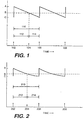
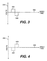
- Figures 1 and 2 depict two cyclic stimulation-relaxation protocols for ventricular pacing, in which the maximum rate of ventricular overdrive pacing is followed by relaxation to a rate just less than the intrinsic atrial firing rate (which corresponds to ventricular escape).
- Figure 1 shows a cyclic saw tooth (linear decay) stimulation-relaxation protocol.
- Figure 2 shows a cyclic exponential decay stimulation-relaxation protocol.
- a cyclic saw tooth stimulation-relaxation protocol for ventricular pacing is depicted with time points 102, 106, and 108 to illustrate initiation of ventricular overdrive pacing at maximum pacing rate A , followed by linear decay/relaxation of the rate of pacing to minimum pacing rate C.
- Each cycle has total time length 110 .
- Intrinsic atrial firing rate B is shown as a dashed reference line. Rate difference A-B is greater than rate difference B-C in this example.
- crossover point 104 is reached when the ventricular pacing rate equals intrinsic atrial firing rate B .
- the period between time point 102 and crossover point 104 represents linear ventricular overdrive pacing period 112
- the period between crossover point 104 and time point 106 represents linear ventricular escape period 114. It is evident that linear ventricular overdrive pacing period 112 is a longer time period than linear ventricular escape period 114 . Therefore, the average ventricular firing rate for this protocol, with the above given relative parameters, will always be slightly greater than intrinsic atrial firing rate B .
- a cyclic exponential decay stimulation-relaxation ventricular pacing protocol is shown with ventricular overdrive pacing to maximum pacing rate A being initiated at time points 202, 206 and 208 , followed by exponential relaxation of the rate of pacing to minimum pacing rate C .
- Each cycle has total time length 210 .
- the time course of the pacing rate during the relaxation phase will be proportional to the time course of the product obtained by multiplying maximum pacing rate A (or the quantity A minus a selected "factor") by the proportionality e 1 / ⁇ , where r is the time constant.
- the selected "factor" typically will have a value less than C .
- dashed line B represents the reference line of intrinsic atrial firing rate.
- two parameters have been adjusted in Figure 2.
- the relaxation of pacing rate is an exponential function of time instead of a linear function of time.
- minimum ventricular pacing rate C is closer to intrinsic atrial firing rate B .
- the period between time point 202 and crossover point 204 represents exponential ventricular overdrive pacing period 212
- the period between crossover point 204 and time point 206 represents exponential ventricular escape period 214
- Rate difference A-B is the same in Figures 1 and 2, as are cycle lengths 110 and 210 . This combination of parameters produces a protocol in which exponential ventricular overdrive pacing period 212 of Figure 2 is shorter than linear ventricular overdrive pacing period 112 of Figure 1.
- linear ventricular overdrive pacing period 112 and linear ventricular escape period 114 reveals that their magnitudes are controlled by variation in single parameter ( A-B )/( B-C ), or any mathematical equivalent, such as ( 102-104 )/( 104-106 ).
- the preferred embodiment of the present invention contemplates any monotonic relaxation protocol, where "monotonic” indicates a unidirectional change in the applied ventricular pacing rate.
- “unidirectional change” is to be understood to refer to a change in ventricular pacing rate that is in the direction of decreasing ventricular pacing rate, and to include periods of time in which there is no change in ventricular pacing rate.
- the preferred embodiment of the present invention contemplates relaxation protocols beyond the two depicted in Figures 1 and 2, as long as the relaxation protocol embodies unidirectional change in ventricular pacing rate as defined above.
- the shapes of the relaxation curves can generally be decreasing linear, decreasing curvilinear, decreasing in an exponential fashion, include one or more periods at a constant pacing rate, or combinations of these.
- a protocol in which, between time points 102 and 104 , there is a small time segment over which the voltage is constant, followed by linear relaxation at the same or a different rate of relaxation (i.e., the same or a different slope) compared to the initial rate of relaxation.
- the same or different rate of relaxation that follows the brief period of constant voltage is maintained up to time point 106 , which marks the end of one cycle and the beginning of the next cycle.
- Alternate embodiments encompass relaxation protocols in which ventricular pacing rates are not monotonic; i.e., as the ventricular pacing rate is declining in a given cycle, time periods in which the ventricular pacing rates are increased slightly can be included. Further alternative embodiments can include the use of combinations of different rates of relaxation within a single cycle, for example, within time segment 102 - 106 , or 202 - 206 .
- physiological data from one or more sensing electrodes are used to determine whether an "action criterion" has been met, in order to initiate a cyclic pacing protocol if the situation so demands.
- Such sensing may be directed to detecting such nonlimiting physiological parameters as abnormal or unacceptably long A-V delays, whether atrial firing entrains both left and right ventricles, length of the QRS complex, magnitude of the QRS complex, heart rate, arterial and/or venous blood pressure, ventricular fibrillation, atrial fibrillation, and probability density function ("PDF").
- PDF probability density function
- the ventricular firing protocol is activated upon detection of a QRS complex, and is set at an overdrive rate of only a few beats per minute (i.e., no more than 3-5 beats per minute) greater than the intrinsic atrial firing rate.
- the ventricular firing rate is slowly decreased ("relaxed") to a rate just a few beats per minute (i.e., no more than 2-3 beats per minute; ideally, only 1-2 beats per minute) below the intrinsic atrial firing rate, which leads to ventricular escape (i.e., atrial firing and contraction no longer coordinate perfectly with ventricular firing and contraction).
- Heart rates could vary from about 40 to 120 beats per minute, with these rates being largely determined by the intrinsic physiology of the heart. Rates that vary greatly from this 40 to 120 beats per minute range would not be beneficial physiologically.
- the ventricular pacing rates hover not far from the intrinsic atrial firing rate so as to minimize the energy requirements of the myocardium.
- practice of the present invention will result in an average ventricular beating rate that is just slightly greater than the intrinsic atrial firing rate.
- some pathological/medical conditions will minimize the cardiac energy requirements with a relaxation protocol that results in an average ventricular beating rate that is equal to, or just slightly less than, the intrinsic atrial firing rate; and such relaxation protocols are well within the scope of the present invention.
- cyclic ventricular pacing with any of the above range of relaxation protocols pertains not only to mono-ventricular pacing, but also to biventricular pacing, and/or pacing from multiple sites.
- right and left ventricles can be cyclically paced either on the same or similar time protocol or independently of one another.
- one pacing electrode or multiple pacing electrodes can be employed per ventricle, and the pacing electrodes can be applied to the external surfaces of the ventricles and/or to the internal surfaces.
- internal pacing electrodes will be applied via the vena cava and the right atrium to the right ventricle only; however, multiple internal pacing electrodes are also contemplated for the left ventricle.
- Additional embodiments encompass the use of monophasic stimulation, as well as biphasic stimulation.
- the monophasic stimulation and the biphasic stimulation can be applied to either atria or ventricles.
- Monophasic stimulation can be either cathodal or anodal, and is known to those skilled in the art.
- Biphasic cardiac stimulation is disclosed in United States Patent Application No. 08/699,552 to Mower , corresponding to U.S. patent 5,871,506.
- a cyclic pacing/relaxation period will fall within the three to 30 second range; however, longer periods also are contemplated, particularly for patients with more "difficult" pathologies.
- Figure 3 depicts biphasic electrical stimulation wherein a first stimulation phase, comprising anodal stimulus 302 , is administered having amplitude 304 and duration 306 . This first stimulation phase is immediately followed by a second stimulation phase comprising cathodal stimulation 308 of equal intensity and duration.
- Figure 4 depicts biphasic electrical stimulation wherein a first stimulation phase, comprising cathodal stimulation 402 having amplitude 404 and duration 406 , is administered. This first stimulation phase is immediately followed by a second stimulation phase comprising anodal stimulation 408 of equal intensity and duration.
- Figure 5 depicts a preferred embodiment of biphasic stimulation wherein a first stimulation phase, comprising low level, long duration anodal stimulation 502 having amplitude 504 and duration 506 , is administered. This first stimulation phase is immediately followed by a second stimulation phase comprising cathodal stimulation 508 of conventional intensity and duration.
- anodal stimulation 502 is: 1) at maximum subthreshold amplitude; 2) less than three volts; 3) of a duration of approximately two to eight milliseconds; and/or 4) administered over 200 milliseconds post heart beat.
- Maximum subthreshold amplitude is understood to mean the maximum stimulation amplitude that can be administered without eliciting a contraction.
- cathodal stimulation 508 is: 1) of a short duration; 2) approximately 0.3 to 1.5 milliseconds; 3) of a high amplitude; 4) in the approximate range of three to twenty volts; and/or 5) of a duration less than 0.3 millisecond and at a voltage greater than twenty volts. In a preferred embodiment, cathodal stimulation is about 0.8 millisecond. In the manner disclosed by these embodiments, as well as those alterations and modifications which can become obvious upon the reading of this specification, a maximum membrane potential without activation is achieved in the first phase of stimulation.
- Figure 6 depicts an alternative preferred embodiment of biphasic stimulation wherein a first stimulation phase, comprising anodal stimulation 602 , is administered over period 604 with rising intensity level 606 .
- the ramp of rising intensity level 606 can be linear or nonlinear, and the slope can vary.
- This anodal stimulation is immediately followed by a second stimulation phase comprising cathodal stimulation 608 of conventional intensity and duration.
- anodal stimulation 602 (1) rises to a maximum subthreshold amplitude less than three volts; (2) is of a duration of approximately two to eight milliseconds; and/or (3) is administered over 200 milliseconds post heart beat.
- cathodal stimulation 608 is: (1) of a short duration; (2) approximately 0.3 to 1.5 milliseconds; (3) of a high amplitude; (4) in the approximate range of three to twenty volts; and/or (5) of a duration less than 0.3 milliseconds and at a voltage greater than twenty volts.
- Figure 7 depicts biphasic electrical stimulation wherein a first stimulation phase, comprising series 702 of anodal pulses, is administered at amplitude 704 .
- rest period 706 is of equal duration to stimulation period 708 , and is administered at baseline amplitude.
- rest period 706 is of a differing duration than stimulation period 708, and is administered at baseline amplitude. Rest period 706 occurs after each stimulation period 708 , with the exception that a second stimulation phase comprising cathodal stimulation 710 of conventional intensity and duration, immediately follows the completion of series 702 .
- cathodal stimulation 710 is: (1) of a short duration; (2) approximately 0.3 to 1.5 milliseconds; (3) of a high amplitude; (4) in the approximate range of three to twenty volts, and/or (5) of a duration less than 0.3 milliseconds and at a voltage greater than twenty volts.
- the preferred practice of the present invention is directed to ventricular pacing where the pacing rate skirts just above and below the intrinsic atrial pacing rate, and is timed (albeit indirectly) relative to intrinsic atrial firing in order to achieve optimal coordinated cardiac function.
- ventricular pacing is effected independently of intrinsic atrial firing.
- the present invention can be practiced with respect to the rhythmicity of pacemaker paced atria.
- the clinical practitioner first sets the rate of atrial pacing, which can be fixed, or can be variable to permit appropriate response to changes in physical activity or other change which would require a change in heart rate, for example, an increased heart rate during a period of fever.
- the ventricular firing protocol is selected according to the principles described and disclosed herein. It is to be emphasized that selection of the ventricular firing protocol generally will be a decision that is made independently of the atrial beating pattern, whether the atrial beating pattern is set intrinsically or extrinsically, for example, by a pacemaker. However, it is within the scope of the present invention to apply the teachings herein to cases in which decisions regarding extrinsically controlled atrial and ventricular beating protocols are considered in a linked, integrated manner.
- testing procedures can be applied to achieve optimal parameters for a given patient with a particular constellation of pathologies.
- alternative stimulation pulse waveforms for example, durations, amplitudes, and shapes of the various waveforms required to reach optimal physiological parameters for a particular patient at a given time.
- various measurable parameters may be used to assess the effects of changes in stimulus waveforms, for example, the effects on pulse pressure, duration of the QRS complex, maximum fusion, and production of a minimal intrinsic heart rate, to name but a few.
Claims (15)
- Implantierbarer Herzstimulator zur Ausführung eines Protokolls zur zyklischen Herzstimulation, wobei das Herz eine intrinsische Vorhof-Impulsauslösungsfrequenz hat,
wobei der Herzstimulator umfaßt:wobei nach dem Protokoll eine Serie von Stimulationsimpulsen mit einer anfänglichen Stimulationsfrequenz an mindestens eine Herzkammer angelegt wird, wobei die anfängliche Stimulationsfrequenz geringfügig größer als die intrinsische Vorhof-Impulsauslösungsfrequenz ist; undmehrere Elektroden, die für das Anlegen von Stimulationsimpulsen an das Herz ausgelegt sind; undeine Impulserzeugungsschaltung, die mit den mehreren Elektroden verbunden und dafür ausgelegt ist, elektrische Impulse als Stimulationsimpulse zu erzeugen;
wobei die Herzkammer-Stimulationsfrequenz mit der Zeit von der anfänglichen Stimulationsfrequenz auf eine minimale Stimulationsfrequenz verringert wird, die geringfügig kleiner als die intrinsische Vorhof-Impulsauslösungsfrequenz ist. - Herzstimulator nach Anspruch 1, ferner mit:einem Sensor für physiologische Parameter, um zu bestimmen, ob die Anwendung des Protokolls zur zyklischen Herzstimulation notwendig ist.
- Implantierbarer Herzstimulator nach Anspruch 2, wobei die physiologischen Parameter aus der Gruppe ausgewählt werden, die folgendes umfaßt: abnormes AV-Intervall, atriales Entrainment der linken und rechten Herzkammer, Länge des QRS-Komplexes, Stärke des QRS-Komplexes, arterieller Blutdruck, venöser Blutdruck, Herzfrequenz, Kammerflimmem, Vorhofflimmern und Wahrscheinlichkeitsdichtefunktion.
- Herzstimulator zur Ausführung eines Protokolls zur zyklischen Herzstimulation,
wobei das Herz eine stimulierte Vorhof-Impulsauslösungsfrequenz hat, wobei der Herzstimulator umfaßt:wobei nach dem Protokoll eine Folge von Stimulationsimpulsen mit einer anfänglichen Stimulationsfrequenz an mindestens eine Herzkammer angelegt wird, wobei die anfängliche Stimulationsfrequenz geringfügig größer als die stimulierte Vorhoffrequenz ist; undmehrere Elektroden, die für das Anlegen von Stimulationsimpulsen an das Herz ausgelegt sind; undeine Impulserzeugungsschaltung, die mit den mehreren Elektroden verbunden und dafür ausgelegt ist, elektrische Impulse als Stimulationsimpulse zu erzeugen;
wobei die Vorhof-Stimulationsfrequenz mit der Zeit von der anfänglichen Stimulationsfrequenz auf eine minimale Stimulationsfrequenz verringert wird, die geringfügig kleiner als die stimulierte Vorhof-Impulsauslösungsfrequenz ist. - Herzstimulator nach einem der Ansprüche 1 oder 4, wobei das Anlegen der Stimulationsimpulse und das Verringern der Stimulationsfrequenz in einem zyklischen Muster wiederholt werden.
- Herzstimulator nach einem der Ansprüche 1 oder 4, wobei ein Protokoll zum Verringern der Stimulationsfrequenz mit der Zeit aus der Gruppe ausgewählt wird, die aus folgendem besteht: linear, krummlinig, exponentiell und Kombinationen daraus.
- Herzstimulator nach einem der Ansprüche 1, 4 oder 6, wobei das Protokoll zum Verringern der Stimulationsfrequenz eine oder mehrere Perioden aufweist, in denen die Stimulationsfrequenz konstant gehalten wird.
- Herzstimulator nach einem der Ansprüche 1 oder 4, wobei die anfängliche Stimulationsfrequenz minus die intrinsische Vorhof-Impulsauslösungsfrequenz größer als die intrinsische Vorhof-Impulsauslösungsfrequenz minus die minimale Stimulationsfrequenz ist.
- Herzstimulator nach einem der Ansprüche 1 oder 4, wobei die anfängliche Stimulationsfrequenz minus die intrinsische Vorhof-Impulsauslösungsfrequenz gleich der intrinsischen Vorhof-Impulsauslösungsfrequenz minus die minimale Stimulationsfrequenz ist.
- Herzstimulator nach einem der Ansprüche 1 oder 4, wobei die anfängliche Stimulationsfrequenz minus die intrinsische Vorhof-Impulsauslösungsfrequenz kleiner als die intrinsische Vorhof-Impulsauslösungsfrequenz minus die minimale Stimulationsfrequenz ist.
- Herzstimulator nach einem der Ansprüche 1 oder 4, wobei die Stimulationsimpulse aus der Gruppe ausgewählt wird, die aus folgendem besteht:einphasige Stimulation und zweiphasige Stimulation.
- Herzstimulator nach Anspruch 11, wobei die einphasige Stimulation aus der Gruppe ausgewählt wird, die aus folgendem besteht: Kathodenstimulation und Anodenstimulation.
- Herzstimulator nach Anspruch 11, wobei die zweiphasige Stimulation eine Anodenstimulationsphase umfaßt, gefolgt von einer Kathodenstimulationsphase, umfaßt.
- Herzstimulator nach Anspruch 13, wobei die Anodenstimulationsphase eine Stärke hat, die gleich oder kleiner als eine maximale Amplitude unterhalb eines Schwellwerts ist, und eine annähernde Form hat, die aus der Gruppe ausgewählt wird, die aus folgendem besteht: Rechteckwelle, Sägezahn und Serie von Rechteckwellen kurzer Dauer.
- Herzstimulator nach einem der Ansprüche 1 oder 4, wobei die Stimulationsimpulse über mehrere Elektroden an mindestens eine Herzkammer angelegt werden.
Priority Applications (1)
| Application Number | Priority Date | Filing Date | Title |
|---|---|---|---|
| SI9930799T SI1079894T1 (en) | 1998-05-26 | 1999-05-21 | Device allowing cyclic pacing with average rate just above the intrinsic heart rate |
Applications Claiming Priority (3)
| Application Number | Priority Date | Filing Date | Title |
|---|---|---|---|
| US84571 | 1998-05-26 | ||
| US09/084,571 US6141586A (en) | 1996-08-19 | 1998-05-26 | Method and apparatus to allow cyclic pacing at an average rate just above the intrinsic heart rate so as to maximize inotropic pacing effects at minimal heart rates |
| PCT/US1999/011375 WO1999061101A1 (en) | 1998-05-26 | 1999-05-21 | Method allowing cyclic pacing with average rate just above the intrinsic rate |
Publications (2)
| Publication Number | Publication Date |
|---|---|
| EP1079894A1 EP1079894A1 (de) | 2001-03-07 |
| EP1079894B1 true EP1079894B1 (de) | 2005-07-20 |
Family
ID=22185823
Family Applications (1)
| Application Number | Title | Priority Date | Filing Date |
|---|---|---|---|
| EP99925765A Expired - Lifetime EP1079894B1 (de) | 1998-05-26 | 1999-05-21 | Vorrichtung zur zyklischen herzreizung mit durchschnittsfrequenz leicht über der intrinsischen herzfrequenz |
Country Status (25)
| Country | Link |
|---|---|
| US (1) | US6141586A (de) |
| EP (1) | EP1079894B1 (de) |
| JP (2) | JP2002516162A (de) |
| KR (1) | KR100423964B1 (de) |
| CN (2) | CN1803219A (de) |
| AT (1) | ATE299736T1 (de) |
| AU (1) | AU755994B2 (de) |
| BR (1) | BR9910702A (de) |
| CA (1) | CA2333363C (de) |
| CZ (1) | CZ298479B6 (de) |
| DE (1) | DE69926232T2 (de) |
| DK (1) | DK1079894T3 (de) |
| EA (1) | EA003572B1 (de) |
| ES (1) | ES2245106T3 (de) |
| GE (1) | GEP20033047B (de) |
| HU (1) | HUP0102153A3 (de) |
| ID (1) | ID27797A (de) |
| IL (1) | IL139780A (de) |
| NO (1) | NO20005959L (de) |
| NZ (1) | NZ508495A (de) |
| PL (1) | PL193754B1 (de) |
| SK (1) | SK286403B6 (de) |
| TR (1) | TR200003358T2 (de) |
| UA (1) | UA49994C2 (de) |
| WO (1) | WO1999061101A1 (de) |
Families Citing this family (108)
| Publication number | Priority date | Publication date | Assignee | Title |
|---|---|---|---|---|
| US6343232B1 (en) | 1966-08-19 | 2002-01-29 | Mower Chf Treatment Irrevocable Trust | Augmentation of muscle contractility by biphasic stimulation |
| US9289618B1 (en) | 1996-01-08 | 2016-03-22 | Impulse Dynamics Nv | Electrical muscle controller |
| US8825152B2 (en) | 1996-01-08 | 2014-09-02 | Impulse Dynamics, N.V. | Modulation of intracellular calcium concentration using non-excitatory electrical signals applied to the tissue |
| US8321013B2 (en) | 1996-01-08 | 2012-11-27 | Impulse Dynamics, N.V. | Electrical muscle controller and pacing with hemodynamic enhancement |
| US7167748B2 (en) | 1996-01-08 | 2007-01-23 | Impulse Dynamics Nv | Electrical muscle controller |
| IL125424A0 (en) * | 1998-07-20 | 1999-03-12 | New Technologies Sa Ysy Ltd | Pacing with hemodynamic enhancement |
| US9713723B2 (en) | 1996-01-11 | 2017-07-25 | Impulse Dynamics Nv | Signal delivery through the right ventricular septum |
| US8447399B2 (en) | 1996-08-19 | 2013-05-21 | Mr3 Medical, Llc | System and method for managing detrimental cardiac remodeling |
| US7840264B1 (en) | 1996-08-19 | 2010-11-23 | Mr3 Medical, Llc | System and method for breaking reentry circuits by cooling cardiac tissue |
| US6337995B1 (en) | 1996-08-19 | 2002-01-08 | Mower Chf Treatment Irrevocable Trust | Atrial sensing and multiple site stimulation as intervention for atrial fibrillation |
| US6341235B1 (en) | 1996-08-19 | 2002-01-22 | Mower Chf Treatment Irrevocable Trust | Augmentation of electrical conduction and contractility by biphasic cardiac pacing administered via the cardiac blood pool |
| US6411847B1 (en) | 1996-08-19 | 2002-06-25 | Morton M. Mower | Apparatus for applying cyclic pacing at an average rate just above the intrinsic heart rate |
| US7908003B1 (en) | 1996-08-19 | 2011-03-15 | Mr3 Medical Llc | System and method for treating ischemia by improving cardiac efficiency |
| US6295470B1 (en) | 1996-08-19 | 2001-09-25 | The Mower Family Chf Treatment Irrevocable Trust | Antitachycardial pacing |
| RU2249039C2 (ru) | 1999-02-04 | 2005-03-27 | Текнион Рисерч Энд Дивелопмент Фаундейшн Лтд. | Способ размножения/поддержания недифференцированных гемопоэтических стволовых клеток или клеток-предшественников (варианты), способ приготовления кондиционированной среды стромальных клеток, способ трансплантации недифференцированных гемопоэтических стволовых клеток или клеток-предшественников (варианты) |
| US6411845B1 (en) | 1999-03-04 | 2002-06-25 | Mower Chf Treatment Irrevocable Trust | System for multiple site biphasic stimulation to revert ventricular arrhythmias |
| US8019421B2 (en) | 1999-03-05 | 2011-09-13 | Metacure Limited | Blood glucose level control |
| US8700161B2 (en) | 1999-03-05 | 2014-04-15 | Metacure Limited | Blood glucose level control |
| US8666495B2 (en) | 1999-03-05 | 2014-03-04 | Metacure Limited | Gastrointestinal methods and apparatus for use in treating disorders and controlling blood sugar |
| US8346363B2 (en) | 1999-03-05 | 2013-01-01 | Metacure Limited | Blood glucose level control |
| US9101765B2 (en) | 1999-03-05 | 2015-08-11 | Metacure Limited | Non-immediate effects of therapy |
| US6473644B1 (en) * | 1999-10-13 | 2002-10-29 | Cyberonics, Inc. | Method to enhance cardiac capillary growth in heart failure patients |
| US6993385B1 (en) | 1999-10-25 | 2006-01-31 | Impulse Dynamics N.V. | Cardiac contractility modulation device having anti-arrhythmic capabilities and a method of operating thereof |
| AU1049901A (en) | 1999-10-25 | 2001-05-08 | Impulse Dynamics N.V. | Cardiac contractility modulation device having anti-arrhythmic capabilities and a method of operating thereof |
| US7308306B1 (en) | 1999-12-23 | 2007-12-11 | Pacesetter, Inc. | System and method for dynamic ventricular overdrive pacing |
| US6519493B1 (en) * | 1999-12-23 | 2003-02-11 | Pacesetter, Inc. | Methods and apparatus for overdrive pacing heart tissue using an implantable cardiac stimulation device |
| US6510342B1 (en) | 2000-04-12 | 2003-01-21 | Pacesetter, Inc. | Methods and apparatus for preventing atrial arrhythmias by overdrive pacing multiple heart tissue sites using an implantable cardiac stimulation device |
| US6606517B1 (en) | 2000-04-12 | 2003-08-12 | Pacesetter, Inc. | Methods and apparatus for preventing atrial arrhythmias by overdrive pacing and prolonging atrial refractoriness using an implantable cardiac stimulation device |
| US6829504B1 (en) * | 2000-09-14 | 2004-12-07 | Cardiac Pacemakers, Inc. | System and method for preventing recurrence of atrial tachyarrhythmia |
| US6622040B2 (en) | 2000-12-15 | 2003-09-16 | Cardiac Pacemakers, Inc. | Automatic selection of stimulation chamber for ventricular resynchronization therapy |
| US9931509B2 (en) | 2000-12-21 | 2018-04-03 | Medtronic, Inc. | Fully inhibited dual chamber pacing mode |
| US7245966B2 (en) | 2000-12-21 | 2007-07-17 | Medtronic, Inc. | Ventricular event filtering for an implantable medical device |
| US7738955B2 (en) * | 2000-12-21 | 2010-06-15 | Medtronic, Inc. | System and method for ventricular pacing with AV interval modulation |
| US7181285B2 (en) * | 2000-12-26 | 2007-02-20 | Cardiac Pacemakers, Inc. | Expert system and method |
| US6738667B2 (en) | 2000-12-28 | 2004-05-18 | Medtronic, Inc. | Implantable medical device for treating cardiac mechanical dysfunction by electrical stimulation |
| US6438408B1 (en) | 2000-12-28 | 2002-08-20 | Medtronic, Inc. | Implantable medical device for monitoring congestive heart failure |
| US7058443B2 (en) * | 2001-04-26 | 2006-06-06 | Medtronic, Inc. | Diagnostic features in biatrial and biventricular pacing systems |
| US6804555B2 (en) | 2001-06-29 | 2004-10-12 | Medtronic, Inc. | Multi-site ventricular pacing system measuring QRS duration |
| US7383088B2 (en) | 2001-11-07 | 2008-06-03 | Cardiac Pacemakers, Inc. | Centralized management system for programmable medical devices |
| US7657482B1 (en) * | 2002-07-15 | 2010-02-02 | Paymentech, L.P. | System and apparatus for transaction fraud processing |
| AU2002323811A1 (en) * | 2002-08-05 | 2004-02-23 | Japan As Represented By President Of National Cardiovascular Center | Subminiature integrated heart pace maker and dispersed heart pacing system |
| US7321794B2 (en) * | 2002-11-15 | 2008-01-22 | Advanced Bionics Corporation | Method and system for treating atrial fibrillation |
| WO2004050561A1 (en) | 2002-12-04 | 2004-06-17 | Idaho Research Foundation, Inc. | Reactive filtration |
| US7136707B2 (en) | 2003-01-21 | 2006-11-14 | Cardiac Pacemakers, Inc. | Recordable macros for pacemaker follow-up |
| ATE471501T1 (de) | 2003-02-10 | 2010-07-15 | N trig ltd | Berührungsdetektion für einen digitalisierer |
| US11439815B2 (en) | 2003-03-10 | 2022-09-13 | Impulse Dynamics Nv | Protein activity modification |
| JP2006519663A (ja) | 2003-03-10 | 2006-08-31 | インパルス ダイナミックス エヌヴイ | 心臓組織内の遺伝子発現を調節するための電気信号を送出する装置及び方法 |
| US8027721B2 (en) * | 2003-03-24 | 2011-09-27 | Physio-Control, Inc. | Balanced charge waveform for transcutaneous pacing |
| US8792985B2 (en) | 2003-07-21 | 2014-07-29 | Metacure Limited | Gastrointestinal methods and apparatus for use in treating disorders and controlling blood sugar |
| US20050055057A1 (en) * | 2003-09-05 | 2005-03-10 | Mirowski Famliy Ventures, L.L.C. | Method and apparatus for providing ipselateral therapy |
| US7123960B2 (en) | 2003-12-22 | 2006-10-17 | Cardiac Pacemakers, Inc. | Method and system for delivering cardiac resynchronization therapy with variable atrio-ventricular delay |
| US7203540B2 (en) * | 2003-12-22 | 2007-04-10 | Cardiac Pacemakers, Inc. | Method and system for setting cardiac resynchronization therapy parameters |
| US7194307B2 (en) * | 2003-12-22 | 2007-03-20 | Cardiac Pacemakers, Inc. | Pacing method and device for preserving native conduction system |
| US8352031B2 (en) | 2004-03-10 | 2013-01-08 | Impulse Dynamics Nv | Protein activity modification |
| US8548583B2 (en) | 2004-03-10 | 2013-10-01 | Impulse Dynamics Nv | Protein activity modification |
| US11779768B2 (en) | 2004-03-10 | 2023-10-10 | Impulse Dynamics Nv | Protein activity modification |
| US7248924B2 (en) * | 2004-10-25 | 2007-07-24 | Medtronic, Inc. | Self limited rate response |
| EP1827571B1 (de) | 2004-12-09 | 2016-09-07 | Impulse Dynamics NV | Proteinaktivitätsmodifizierung |
| US20060149184A1 (en) * | 2005-01-06 | 2006-07-06 | Orhan Soykan | Myocardial stimulation |
| US7542799B2 (en) * | 2005-01-21 | 2009-06-02 | Medtronic, Inc. | Implantable medical device with ventricular pacing protocol |
| US7593773B2 (en) * | 2005-01-21 | 2009-09-22 | Medtronic, Inc. | Implantable medical device with ventricular pacing protocol including progressive conduction search |
| US9821158B2 (en) | 2005-02-17 | 2017-11-21 | Metacure Limited | Non-immediate effects of therapy |
| US8244371B2 (en) | 2005-03-18 | 2012-08-14 | Metacure Limited | Pancreas lead |
| US7650181B2 (en) * | 2005-09-14 | 2010-01-19 | Zoll Medical Corporation | Synchronization of repetitive therapeutic interventions |
| US7826897B2 (en) * | 2005-12-22 | 2010-11-02 | Cardiac Pacemakers, Inc. | Cardiac pacemaker with pacing rate monitoring |
| US7925344B2 (en) * | 2006-01-20 | 2011-04-12 | Medtronic, Inc. | System and method of using AV conduction timing |
| US8046063B2 (en) * | 2006-02-28 | 2011-10-25 | Medtronic, Inc. | Implantable medical device with adaptive operation |
| US7697987B2 (en) | 2006-04-26 | 2010-04-13 | Medtronic, Inc. | Method and system for detecting cardiac arrhythmias during overdrive pacing |
| US8838244B2 (en) * | 2006-06-02 | 2014-09-16 | Semiconductor Energy Laboratory Co., Ltd. | Cardiac pacemaker device with circuits for monitoring residual capacity of battery |
| US7565196B2 (en) * | 2006-06-15 | 2009-07-21 | Medtronic, Inc. | System and method for promoting intrinsic conduction through atrial timing |
| US7869872B2 (en) * | 2006-06-15 | 2011-01-11 | Medtronic, Inc. | System and method for determining intrinsic AV interval timing |
| US7894898B2 (en) * | 2006-06-15 | 2011-02-22 | Medtronic, Inc. | System and method for ventricular interval smoothing following a premature ventricular contraction |
| US7783350B2 (en) * | 2006-06-15 | 2010-08-24 | Medtronic, Inc. | System and method for promoting intrinsic conduction through atrial timing modification and calculation of timing parameters |
| US7715914B2 (en) * | 2006-07-31 | 2010-05-11 | Medtronic, Inc. | System and method for improving ventricular sensing |
| US7502647B2 (en) | 2006-07-31 | 2009-03-10 | Medtronic, Inc. | Rate smoothing pacing modality with increased ventricular sensing |
| US7720537B2 (en) | 2006-07-31 | 2010-05-18 | Medtronic, Inc. | System and method for providing improved atrial pacing based on physiological need |
| US7515958B2 (en) * | 2006-07-31 | 2009-04-07 | Medtronic, Inc. | System and method for altering pacing modality |
| US7856269B2 (en) | 2006-07-31 | 2010-12-21 | Medtronic, Inc. | System and method for determining phsyiologic events during pacing mode operation |
| US7689281B2 (en) | 2006-07-31 | 2010-03-30 | Medtronic, Inc. | Pacing mode event classification with increased ventricular sensing |
| US7502646B2 (en) * | 2006-07-31 | 2009-03-10 | Medtronic, Inc. | Pacing mode event classification with rate smoothing and increased ventricular sensing |
| WO2009135089A1 (en) * | 2008-04-30 | 2009-11-05 | Medtronic, Inc. | Techniques for placing medical leads for electrical stimulation of nerve tissue |
| US8452394B2 (en) | 2008-10-31 | 2013-05-28 | Medtronic, Inc. | Implantable medical device crosstalk evaluation and mitigation |
| US8260412B2 (en) | 2008-10-31 | 2012-09-04 | Medtronic, Inc. | Implantable medical device crosstalk evaluation and mitigation |
| US8560060B2 (en) | 2008-10-31 | 2013-10-15 | Medtronic, Inc. | Isolation of sensing and stimulation circuitry |
| US9775987B2 (en) | 2008-10-31 | 2017-10-03 | Medtronic, Inc. | Implantable medical device crosstalk evaluation and mitigation |
| US8005539B2 (en) * | 2008-10-31 | 2011-08-23 | Medtronic, Inc. | Implantable medical device crosstalk evaluation and mitigation |
| US9597505B2 (en) * | 2008-10-31 | 2017-03-21 | Medtronic, Inc. | Implantable medical device crosstalk evaluation and mitigation |
| US8611996B2 (en) | 2008-10-31 | 2013-12-17 | Medtronic, Inc. | Implantable medical device crosstalk evaluation and mitigation |
| US8527045B2 (en) * | 2008-10-31 | 2013-09-03 | Medtronic, Inc. | Therapy system including cardiac rhythm therapy and neurostimulation capabilities |
| US9192769B2 (en) * | 2008-10-31 | 2015-11-24 | Medtronic, Inc. | Shunt-current reduction techniques for an implantable therapy system |
| US8532779B2 (en) * | 2008-10-31 | 2013-09-10 | Medtronic, Inc. | Implantable medical device crosstalk evaluation and mitigation |
| US8498698B2 (en) | 2008-10-31 | 2013-07-30 | Medtronic, Inc. | Isolation of sensing and stimulation circuitry |
| US8774918B2 (en) * | 2008-10-31 | 2014-07-08 | Medtronic, Inc. | Implantable medical device crosstalk evaluation and mitigation |
| EP2367596A1 (de) * | 2008-10-31 | 2011-09-28 | Medtronic, Inc. | Shunt-strom-reduzierungsgehäuse für ein implantierbares therapiesystem |
| US8249708B2 (en) * | 2008-10-31 | 2012-08-21 | Medtronic, Inc. | Implantable medical device crosstalk evaluation and mitigation |
| US8688210B2 (en) * | 2008-10-31 | 2014-04-01 | Medtronic, Inc. | Implantable medical device crosstalk evaluation and mitigation |
| WO2010099382A1 (en) * | 2009-02-27 | 2010-09-02 | Medtronic, Inc. | System and method for conditional biventricular pacing |
| EP2403592B1 (de) * | 2009-02-27 | 2016-06-29 | Medtronic, Inc | System für konditionales biventrikuläres pacing |
| EP2403590B1 (de) * | 2009-02-27 | 2016-07-13 | Medtronic, Inc | System für konditionales biventrikuläres pacing |
| CN101612451B (zh) * | 2009-07-31 | 2011-05-18 | 广东省医疗器械研究所 | 可充电的植入性心脏起搏器设备及其充电方法 |
| WO2011092710A2 (en) | 2010-02-01 | 2011-08-04 | Metacure Limited | Gastrointestinal electrical therapy |
| US8600504B2 (en) | 2010-07-02 | 2013-12-03 | Cardiac Pacemakers, Inc. | Physiologic demand driven pacing |
| US8478407B2 (en) | 2011-07-28 | 2013-07-02 | Medtronic, Inc. | Methods for promoting intrinsic activation in single chamber implantable cardiac pacing systems |
| US8543204B2 (en) * | 2011-12-22 | 2013-09-24 | Medtronic, Inc. | Timing pacing pulses in single chamber implantable cardiac pacemaker systems |
| US20140323928A1 (en) | 2013-04-30 | 2014-10-30 | Zoll Medical Corporation | Compression Depth Monitor with Variable Release Velocity Feedback |
| US9186516B2 (en) * | 2013-05-22 | 2015-11-17 | Mr3 Medical, Llc | System for stimulating the heart via storage of multi-waveforms in a cardiac stimulation device |
| CN107480413B (zh) * | 2016-06-07 | 2020-08-04 | 创领心律管理医疗器械(上海)有限公司 | 治疗心律失常的医疗设备及其房室间期搜索方法 |
| CN111789590B (zh) * | 2019-04-08 | 2022-04-12 | 四川锦江电子科技有限公司 | 一种人体心腔内刺激与电生理记录同步记录的方法和系统 |
Family Cites Families (35)
| Publication number | Priority date | Publication date | Assignee | Title |
|---|---|---|---|---|
| GB1459397A (en) * | 1973-03-22 | 1976-12-22 | Biopulse Co Ltd | Apparatus for treating organisms by applying an electrical signal thereto |
| US3924641A (en) * | 1974-08-19 | 1975-12-09 | Axotronics Inc | Bi-phasic current stimulation system |
| US4343312A (en) * | 1979-04-16 | 1982-08-10 | Vitafin N.V. | Pacemaker output circuit |
| US4298007A (en) * | 1980-07-21 | 1981-11-03 | Cardiac Pacemakers, Inc. | Atrial rate sensitive cardiac pacer circuit |
| US4402322A (en) * | 1981-03-25 | 1983-09-06 | Medtronic, Inc. | Pacer output circuit |
| DE3175940D1 (en) * | 1981-10-26 | 1987-04-09 | Vitafin Nv | Programmable cardiac pacemaker |
| US4444195A (en) * | 1981-11-02 | 1984-04-24 | Cordis Corporation | Cardiac lead having multiple ring electrodes |
| US4429697A (en) * | 1982-04-12 | 1984-02-07 | Telectronics Pty. Ltd. | Dual chamber heart pacer with improved ventricular rate control |
| US4498478A (en) * | 1982-09-13 | 1985-02-12 | Medtronic, Inc. | Apparatus for reducing polarization potentials in a pacemaker |
| DE3246266A1 (de) * | 1982-12-14 | 1984-06-14 | Siemens AG, 1000 Berlin und 8000 München | Verfahren/einrichtung zur desinfektion von wasserwegen in medizinischen, insbesondere zahnmedizinischen, geraeten |
| US4903700A (en) * | 1986-08-01 | 1990-02-27 | Telectronics N.V. | Pacing pulse compensation |
| US5105810A (en) * | 1990-07-24 | 1992-04-21 | Telectronics Pacing Systems, Inc. | Implantable automatic and haemodynamically responsive cardioverting/defibrillating pacemaker with means for minimizing bradycardia support pacing voltages |
| ES2092554T3 (es) * | 1990-12-18 | 1996-12-01 | Ventritex Inc | Aparato para producir formas de onda desfibriladoras bifasicas configurables. |
| WO1993001861A1 (en) * | 1991-07-15 | 1993-02-04 | Zmd Corporation | Method and apparatus for transcutaneous cardiac pacing |
| US5534015A (en) * | 1992-02-18 | 1996-07-09 | Angeion Corporation | Method and apparatus for generating biphasic waveforms in an implantable defibrillator |
| SE9202630D0 (sv) * | 1992-09-14 | 1992-09-14 | Hans Schueller | Pacemaker |
| US5334220A (en) * | 1992-11-13 | 1994-08-02 | Siemens Pacesetter, Inc. | Dual-chamber implantable pacemaker having an adaptive AV interval that prevents ventricular fusion beats and method of operating same |
| US5340361A (en) * | 1992-11-13 | 1994-08-23 | Siemens Pacesetter, Inc. | Implantable pacemaker having adaptive AV interval adoptively shortened to assure ventricular pacing |
| US5350401A (en) * | 1993-03-26 | 1994-09-27 | Siemens Pacesetter, Inc. | Implantable cardioverter/defibrillator device having means for determining and treating low amplitude ventricular fibrillation and method thereof |
| US5423868A (en) * | 1994-04-12 | 1995-06-13 | Telectronics Pacing Systems, Inc. | Dual chamber pacemaker which detects, confirms and terminates pacemaker mediated tachycardia |
| US5522858A (en) | 1994-10-26 | 1996-06-04 | Vitatron Medical, B.V. | Pacemaker with improved reaction to stable first degree atrio-ventricular block |
| US5480413A (en) * | 1994-11-30 | 1996-01-02 | Telectronics Pacing Systems, Inc. | Apparatus and method for stabilizing the ventricular rate of a heart during atrial fibrillation |
| US5601608A (en) * | 1995-02-02 | 1997-02-11 | Pacesetter, Inc. | Methods and apparatus for applying charge-balanced antiarrhythmia shocks |
| SE9500620D0 (sv) * | 1995-02-20 | 1995-02-20 | Pacesetter Ab | Anordning för hjärtstimulering |
| US5626620A (en) * | 1995-02-21 | 1997-05-06 | Medtronic, Inc. | Dual chamber pacing system and method with continual adjustment of the AV escape interval so as to maintain optimized ventricular pacing for treating cardiomyopathy |
| US5527347A (en) * | 1995-02-21 | 1996-06-18 | Medtronic, Inc. | Dual chamber pacing system and method with automatic adjustment of the AV escape interval for treating cardiomyopathy |
| US5514163A (en) * | 1995-02-21 | 1996-05-07 | Medtronic, Inc. | Dual chamber pacing system and method with optimized adjustment of the AV escape interval for treating cardiomyopathy |
| US5545186A (en) * | 1995-03-30 | 1996-08-13 | Medtronic, Inc. | Prioritized rule based method and apparatus for diagnosis and treatment of arrhythmias |
| IL148948A0 (en) * | 1996-01-08 | 2002-11-10 | Impulse Dynamics Nv | Electrical muscle controller |
| US5713929A (en) * | 1996-05-03 | 1998-02-03 | Medtronic, Inc. | Arrhythmia and fibrillation prevention pacemaker using ratchet up and decay modes of operation |
| US5968081A (en) * | 1996-05-15 | 1999-10-19 | Pacesetter, Inc. | System and method for providing improved fallback response in a dual-chamber cardiac pacemaker |
| US5800465A (en) * | 1996-06-18 | 1998-09-01 | Medtronic, Inc. | System and method for multisite steering of cardiac stimuli |
| US5871506A (en) * | 1996-08-19 | 1999-02-16 | Mower; Morton M. | Augmentation of electrical conduction and contractility by biphasic cardiac pacing |
| US5814079A (en) * | 1996-10-04 | 1998-09-29 | Medtronic, Inc. | Cardiac arrhythmia management by application of adnodal stimulation for hyperpolarization of myocardial cells |
| FR2763247B1 (fr) * | 1997-05-16 | 2000-02-18 | Ela Medical Sa | Dispositif medical implantable actif, notamment stimulateur cardiaque, defibrillateur et/ou cardioverteur a reduction des episodes d'arythmie, notamment d'arythmie auriculaire |
-
1998
- 1998-05-26 US US09/084,571 patent/US6141586A/en not_active Expired - Lifetime
-
1999
- 1999-05-21 WO PCT/US1999/011375 patent/WO1999061101A1/en active IP Right Grant
- 1999-05-21 BR BR9910702-3A patent/BR9910702A/pt not_active Application Discontinuation
- 1999-05-21 UA UA2000127489A patent/UA49994C2/uk unknown
- 1999-05-21 DK DK99925765T patent/DK1079894T3/da active
- 1999-05-21 AU AU41984/99A patent/AU755994B2/en not_active Ceased
- 1999-05-21 CN CNA2005101200542A patent/CN1803219A/zh active Pending
- 1999-05-21 CZ CZ20004238A patent/CZ298479B6/cs not_active IP Right Cessation
- 1999-05-21 TR TR2000/03358T patent/TR200003358T2/xx unknown
- 1999-05-21 KR KR10-2000-7013231A patent/KR100423964B1/ko not_active IP Right Cessation
- 1999-05-21 PL PL99344392A patent/PL193754B1/pl not_active IP Right Cessation
- 1999-05-21 IL IL139780A patent/IL139780A/en not_active IP Right Cessation
- 1999-05-21 ES ES99925765T patent/ES2245106T3/es not_active Expired - Lifetime
- 1999-05-21 ID IDW20002442A patent/ID27797A/id unknown
- 1999-05-21 SK SK1801-2000A patent/SK286403B6/sk unknown
- 1999-05-21 EP EP99925765A patent/EP1079894B1/de not_active Expired - Lifetime
- 1999-05-21 CN CNB99806596XA patent/CN1235651C/zh not_active Expired - Fee Related
- 1999-05-21 AT AT99925765T patent/ATE299736T1/de not_active IP Right Cessation
- 1999-05-21 GE GEAP19995685A patent/GEP20033047B/en unknown
- 1999-05-21 JP JP2000550556A patent/JP2002516162A/ja active Pending
- 1999-05-21 NZ NZ508495A patent/NZ508495A/en unknown
- 1999-05-21 EA EA200001225A patent/EA003572B1/ru not_active IP Right Cessation
- 1999-05-21 DE DE69926232T patent/DE69926232T2/de not_active Expired - Lifetime
- 1999-05-21 HU HU0102153A patent/HUP0102153A3/hu unknown
- 1999-05-21 CA CA002333363A patent/CA2333363C/en not_active Expired - Fee Related
-
2000
- 2000-11-24 NO NO20005959A patent/NO20005959L/no not_active Application Discontinuation
-
2005
- 2005-03-22 JP JP2005082143A patent/JP2005230566A/ja not_active Abandoned
Also Published As
Similar Documents
| Publication | Publication Date | Title |
|---|---|---|
| EP1079894B1 (de) | Vorrichtung zur zyklischen herzreizung mit durchschnittsfrequenz leicht über der intrinsischen herzfrequenz | |
| US6411847B1 (en) | Apparatus for applying cyclic pacing at an average rate just above the intrinsic heart rate | |
| US5800467A (en) | Cardio-synchronous impedance measurement system for an implantable stimulation device | |
| US6718206B2 (en) | Permanent atrial-his-ventricular sequential pacing | |
| US6804555B2 (en) | Multi-site ventricular pacing system measuring QRS duration | |
| JP3548182B2 (ja) | 左心a−v間隔を最適化するための自動a−vプログラム機能を備えた心臓ペースメーカ装置 | |
| EP3094373B1 (de) | Optimierung einer herzresynchronisationstherapie auf der basis von intrakardialer impedanz | |
| AU2008289617B2 (en) | Method, apparatus, and system to optimize cardiac preload based on measured pulmonary artery pressure | |
| EP1954346A2 (de) | Herzschrittmacher mit dynamischer leitungszeitüberwachung | |
| JP2001520093A (ja) | レート適合型t波検出を行う埋込み型心臓刺激装置 | |
| EP1539297B1 (de) | Herzschrittmachervorrichtung mit variablem stimulationssicherheitsabstand | |
| CN116133595A (zh) | 用于心力衰竭治疗的起搏疗法选择 | |
| US11351383B2 (en) | Left ventricular capture and synchronization verification using a single multi-electrode coronary sinus lead | |
| US8620424B2 (en) | Method and apparatus for providing extra systolic stimulation | |
| MXPA00011421A (en) | Method allowing cyclic pacing with average rate just above the intrinsic rate |
Legal Events
| Date | Code | Title | Description |
|---|---|---|---|
| PUAI | Public reference made under article 153(3) epc to a published international application that has entered the european phase |
Free format text: ORIGINAL CODE: 0009012 |
|
| 17P | Request for examination filed |
Effective date: 20001215 |
|
| AK | Designated contracting states |
Kind code of ref document: A1 Designated state(s): AT DE DK ES FI FR GB SE |
|
| AX | Request for extension of the european patent |
Free format text: LT PAYMENT 20001214;LV PAYMENT 20001214;SI PAYMENT 20001214 |
|
| GRAP | Despatch of communication of intention to grant a patent |
Free format text: ORIGINAL CODE: EPIDOSNIGR1 |
|
| RTI1 | Title (correction) |
Free format text: DEVICE ALLOWING CYCLIC PACING WITH AVERAGE RATE JUST ABOVE THE INTRINSIC HEART RATE |
|
| GRAS | Grant fee paid |
Free format text: ORIGINAL CODE: EPIDOSNIGR3 |
|
| GRAA | (expected) grant |
Free format text: ORIGINAL CODE: 0009210 |
|
| AK | Designated contracting states |
Kind code of ref document: B1 Designated state(s): AT DE DK ES FI FR GB SE |
|
| AX | Request for extension of the european patent |
Extension state: LT LV SI |
|
| REG | Reference to a national code |
Ref country code: GB Ref legal event code: FG4D |
|
| REG | Reference to a national code |
Ref country code: SE Ref legal event code: TRGR |
|
| REF | Corresponds to: |
Ref document number: 69926232 Country of ref document: DE Date of ref document: 20050825 Kind code of ref document: P |
|
| REG | Reference to a national code |
Ref country code: DK Ref legal event code: T3 |
|
| REG | Reference to a national code |
Ref country code: ES Ref legal event code: FG2A Ref document number: 2245106 Country of ref document: ES Kind code of ref document: T3 |
|
| ET | Fr: translation filed | ||
| PLBE | No opposition filed within time limit |
Free format text: ORIGINAL CODE: 0009261 |
|
| STAA | Information on the status of an ep patent application or granted ep patent |
Free format text: STATUS: NO OPPOSITION FILED WITHIN TIME LIMIT |
|
| 26N | No opposition filed |
Effective date: 20060421 |
|
| PGFP | Annual fee paid to national office [announced via postgrant information from national office to epo] |
Ref country code: ES Payment date: 20080526 Year of fee payment: 10 Ref country code: DK Payment date: 20080528 Year of fee payment: 10 |
|
| PGFP | Annual fee paid to national office [announced via postgrant information from national office to epo] |
Ref country code: AT Payment date: 20080502 Year of fee payment: 10 |
|
| PGFP | Annual fee paid to national office [announced via postgrant information from national office to epo] |
Ref country code: FI Payment date: 20080530 Year of fee payment: 10 |
|
| PGFP | Annual fee paid to national office [announced via postgrant information from national office to epo] |
Ref country code: SE Payment date: 20090601 Year of fee payment: 11 |
|
| LTLA | Lt: lapse of european patent or patent extension |
Effective date: 20090521 |
|
| REG | Reference to a national code |
Ref country code: DK Ref legal event code: EBP |
|
| PG25 | Lapsed in a contracting state [announced via postgrant information from national office to epo] |
Ref country code: FI Free format text: LAPSE BECAUSE OF NON-PAYMENT OF DUE FEES Effective date: 20090521 Ref country code: AT Free format text: LAPSE BECAUSE OF NON-PAYMENT OF DUE FEES Effective date: 20090521 |
|
| REG | Reference to a national code |
Ref country code: SI Ref legal event code: KO00 Effective date: 20100201 |
|
| PG25 | Lapsed in a contracting state [announced via postgrant information from national office to epo] |
Ref country code: DK Free format text: LAPSE BECAUSE OF NON-PAYMENT OF DUE FEES Effective date: 20090531 |
|
| REG | Reference to a national code |
Ref country code: ES Ref legal event code: FD2A Effective date: 20090522 |
|
| PG25 | Lapsed in a contracting state [announced via postgrant information from national office to epo] |
Ref country code: ES Free format text: LAPSE BECAUSE OF NON-PAYMENT OF DUE FEES Effective date: 20090522 |
|
| EUG | Se: european patent has lapsed | ||
| PG25 | Lapsed in a contracting state [announced via postgrant information from national office to epo] |
Ref country code: SE Free format text: LAPSE BECAUSE OF NON-PAYMENT OF DUE FEES Effective date: 20100522 |
|
| PGFP | Annual fee paid to national office [announced via postgrant information from national office to epo] |
Ref country code: DE Payment date: 20130530 Year of fee payment: 15 Ref country code: GB Payment date: 20130528 Year of fee payment: 15 |
|
| PGFP | Annual fee paid to national office [announced via postgrant information from national office to epo] |
Ref country code: FR Payment date: 20130702 Year of fee payment: 15 |
|
| REG | Reference to a national code |
Ref country code: DE Ref legal event code: R119 Ref document number: 69926232 Country of ref document: DE |
|
| GBPC | Gb: european patent ceased through non-payment of renewal fee |
Effective date: 20140521 |
|
| REG | Reference to a national code |
Ref country code: FR Ref legal event code: ST Effective date: 20150130 |
|
| REG | Reference to a national code |
Ref country code: DE Ref legal event code: R119 Ref document number: 69926232 Country of ref document: DE Effective date: 20141202 |
|
| PG25 | Lapsed in a contracting state [announced via postgrant information from national office to epo] |
Ref country code: DE Free format text: LAPSE BECAUSE OF NON-PAYMENT OF DUE FEES Effective date: 20141202 |
|
| PG25 | Lapsed in a contracting state [announced via postgrant information from national office to epo] |
Ref country code: FR Free format text: LAPSE BECAUSE OF NON-PAYMENT OF DUE FEES Effective date: 20140602 Ref country code: GB Free format text: LAPSE BECAUSE OF NON-PAYMENT OF DUE FEES Effective date: 20140521 |