EP1079646B1 - Verfahren, Einrichtung in einem mobilen Übertragungssystem und Aufzeichnungsmedium zur Übertragungsleistungsrechnung und zur Blockierungswahrscheinlichkeitsrechnung - Google Patents
Verfahren, Einrichtung in einem mobilen Übertragungssystem und Aufzeichnungsmedium zur Übertragungsleistungsrechnung und zur Blockierungswahrscheinlichkeitsrechnung Download PDFInfo
- Publication number
- EP1079646B1 EP1079646B1 EP00306879A EP00306879A EP1079646B1 EP 1079646 B1 EP1079646 B1 EP 1079646B1 EP 00306879 A EP00306879 A EP 00306879A EP 00306879 A EP00306879 A EP 00306879A EP 1079646 B1 EP1079646 B1 EP 1079646B1
- Authority
- EP
- European Patent Office
- Prior art keywords
- base station
- calculating
- communication performance
- load
- threshold value
- Prior art date
- Legal status (The legal status is an assumption and is not a legal conclusion. Google has not performed a legal analysis and makes no representation as to the accuracy of the status listed.)
- Expired - Lifetime
Links
Images


Classifications
-
- H—ELECTRICITY
- H04—ELECTRIC COMMUNICATION TECHNIQUE
- H04W—WIRELESS COMMUNICATION NETWORKS
- H04W24/00—Supervisory, monitoring or testing arrangements
-
- H—ELECTRICITY
- H04—ELECTRIC COMMUNICATION TECHNIQUE
- H04B—TRANSMISSION
- H04B17/00—Monitoring; Testing
-
- H—ELECTRICITY
- H04—ELECTRIC COMMUNICATION TECHNIQUE
- H04W—WIRELESS COMMUNICATION NETWORKS
- H04W52/00—Power management, e.g. TPC [Transmission Power Control], power saving or power classes
- H04W52/04—TPC
- H04W52/18—TPC being performed according to specific parameters
- H04W52/24—TPC being performed according to specific parameters using SIR [Signal to Interference Ratio] or other wireless path parameters
-
- H—ELECTRICITY
- H04—ELECTRIC COMMUNICATION TECHNIQUE
- H04W—WIRELESS COMMUNICATION NETWORKS
- H04W52/00—Power management, e.g. TPC [Transmission Power Control], power saving or power classes
- H04W52/04—TPC
- H04W52/30—TPC using constraints in the total amount of available transmission power
- H04W52/34—TPC management, i.e. sharing limited amount of power among users or channels or data types, e.g. cell loading
-
- H—ELECTRICITY
- H04—ELECTRIC COMMUNICATION TECHNIQUE
- H04W—WIRELESS COMMUNICATION NETWORKS
- H04W52/00—Power management, e.g. TPC [Transmission Power Control], power saving or power classes
- H04W52/04—TPC
- H04W52/18—TPC being performed according to specific parameters
- H04W52/24—TPC being performed according to specific parameters using SIR [Signal to Interference Ratio] or other wireless path parameters
- H04W52/243—TPC being performed according to specific parameters using SIR [Signal to Interference Ratio] or other wireless path parameters taking into account interferences
-
- H—ELECTRICITY
- H04—ELECTRIC COMMUNICATION TECHNIQUE
- H04W—WIRELESS COMMUNICATION NETWORKS
- H04W52/00—Power management, e.g. TPC [Transmission Power Control], power saving or power classes
- H04W52/04—TPC
- H04W52/30—TPC using constraints in the total amount of available transmission power
- H04W52/34—TPC management, i.e. sharing limited amount of power among users or channels or data types, e.g. cell loading
- H04W52/343—TPC management, i.e. sharing limited amount of power among users or channels or data types, e.g. cell loading taking into account loading or congestion level
Definitions
- the present invention relates to a communication performance calculation method and a communication performance calculation apparatus in a mobile communication system, and a blocking probability calculation method and a blocking probability calculation apparatus in a communication system, and a recording medium. More particularly, the present invention relates to a method and apparatus for calculating performance such as the blocking probability (the probability of rejection of a new call to the system) in a base station, or the probability of degradation in the communication performance due to traffic concentration, and a recording medium associated therewith. The present invention also relates to a method and apparatus for calculating the blocking probability in a mobile communication system, and a recording medium associated therewith.
- a mobile communication system like a widespread mobile telephone system today, the entire service area is usually divided into rather small areas called cells to provide services.
- Such a system comprises as shown in Fig. 1 , for example, a plurality of base stations 102 for covering divided cells 106, and mobile stations 104 for conducting communication with the base stations 102 by establishing radio channels with the base stations.
- the radio waves transmitted from the base stations 102 or mobile stations 104 at certain transmission power travel through the space with some attenuation and arrive at a receiving point.
- the attenuation the radio waves undergo usually increases with the distance between the transmitting site and the receiving site.
- the propagation loss varies greatly due to the surrounding geography and conditions of objects because the radio waves undergo blocking, reflection and diffraction by large buildings, mountains or hills.
- the receiving side requires received power higher than a certain level to receive and demodulate signals at a prescribed level of quality. Accordingly, it very important for area design in mobile communication systems to cover the service area efficiently by utilizing limited transmission power.
- a method which estimates radio wave propagation conditions in the service areas by simulating the radio wave propagation from the specifications of the base stations and mobile stations and geographic data using a computer.
- a method is described, for example, in " Cell Design System in Mobile Communication” by Fujii, Asakura and Yamazaki, NTT DoCoMo Technical Journal Vol. 1, No. 4, pp. 28-34, 1995-01 , or in " Total Support System for Station Establishment Design” by Ohmatuzawa and Yamashita, NTT DoCoMo Technical Journal Vol. 4, No. 1, pp. 28-31, 1996-04 .
- These methods divide the cells into smaller subdivisions, store altitude data, geographic data and communication traffic data of individual subdivisions, and calculate the signal-to-interference ratio (SIR) at each receiving site or traffic for each base station.
- SIR signal-to-interference ratio
- FDMA frequency division multiple access
- TDMA time division multiple access
- CDMA code division multiple access
- the conventional scheme does not consider the total downlink transmission power that serves as an important index in the CDMA system, it has a great problem of being inapplicable to the CDMA system without change.
- a general communication system such as a fixed telephone system or mobile telephone system
- many users share communication resources. For example, consider an office telephone system shared by ten employees. The probability that the ten employees conduct telephone conversations at the same time is very small, nearly zero. Thus, the number of circuits required in the office can be less than ten, and the employees share the limited number of channels, use them when necessary, and release them after their conversations so that other employees can use them. However, it sometimes takes place that no channel is available because all the channels are busy. In such a case, many of the present communication systems reject a new call, resulting in a call loss. It is preferable that the number of channels be as small as possible from an economical point of view.
- Such consideration about the office telephone system is also applicable to the fixed telephone system and the mobile communication system, as well.
- the mobile communication system communications between the base stations and mobile stations are established using radio transmission, and the resources the communications use are radio channels. Since the frequency band available for the mobile communication system is generally limited, the resource sharing becomes a more serious issue than in the fixed telephone network that uses wired circuits for information transmission.
- radio channel access schemes the mobile communication usually utilizes, there are frequency division multiple access (FDMA), time division multiple access (TDMA) or code division multiple access (CDMA).
- the number of radio channels to be assigned to the stations can be designed using the Erlang B formula as in the conventional system because the radio frequencies available are assigned to the base stations in advance.
- the conventional method is inapplicable.
- Expression (1) corresponds to calculating the probability that the normalized interference, which is assumed to have the normal distribution, exceeds the threshold value A.
- the interference power reduces when the call loss is present, and accurate calculation of the blocking probability is impossible without considering the reduction in the interference power due to the call loss.
- Fig. 14 is a block diagram illustrating the calculation of the blocking probability by the conventional technique (disclosed by the foregoing paper).
- the method described in the paper calculates the blocking probability without considering the reduction in the interference power due to the call loss. Thus, it has a serious problem of being unable to calculate the blocking probability accurately.
- US 5,293,640 discloses a generator for simulating interference power. As interference varies in dependence upon the instantaneous position of the mobile unit, the interference power results are characterised by means of a distribution function. The distribution function is approximated near to the generator, the mean value and deviation being calculated from interference field strengths.
- an object of the present invention is to provide a method and the like of accurately and simply calculating the performance in a base station by calculating the traffic distribution in the base station in a mobile communication system.
- Another object of the present invention is to provide a method and the like of simply and accurately calculating the blocking probability in a mobile communication system.
- the present invention modifies the load (such as applied traffic (applied traffic intensity), interference power, transmission power of the base station) in the mobile communication system by using a dummy generated within the system. This makes it possible to model the reduction in the load due to call loss which is not considered conventionally, and to better simulate an actual model by the simplified calculation of the blocking probability, thereby improving the accuracy of the blocking probability.
- the present invention determines the amount of change of the dummy on the basis of the blocking probability calculated and the dummy generated within the system, and calculates the blocking probability with varying the dummy. This makes it possible to bring the blocking probability and load reduction into balance, thereby improving the accuracy of the blocking Probability.
- a communication performance calculation method in a mobile communication system which includes a plurality of base stations and a plurality of mobile stations for carrying out communication with the base stations, wherein an area where the mobile stations are distributed is divided into a plurality of subdivisions, said communication performance calculation method being characterized by comprising:
- a computer readable recording medium storing a program causing a computer to execute a communication performance calculation method in a mobile communication system which includes a plurality of base stations and a plurality of mobile stations for carrying out communication with the base stations, wherein an area where the mobile stations are distributed is divided into a plurality of subdivisions, said communication performance calculation method characterized by comprising:
- a communication performance calculation apparatus in a mobile communication system which includes a plurality of base stations and a plurality of mobile stations for carrying out communication with the base stations, wherein an area where the mobile stations are distributed is divided into a plurality of subdivisions, said communication performance calculation apparatus characterized by comprising:
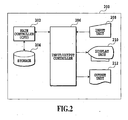
- FIG. 2 is a block diagram showing a hardware configuration of a performance calculation apparatus of an embodiment in accordance with the present invention.
- a performance calculation apparatus 200 of the present embodiment comprises a main controller 202, a storage 204, an input/output controller 206, an input unit 208, a display unit 210 and an output unit 212, and can consist of a personal computer, for example.
- the left-hand side of Fig. 3 illustrates that each cell is divided into a plurality of subdivisions in the present invention.
- the right-hand side of Fig. 3 illustrates that the storage such as a fixed disk or memory stores for each subdivision at least one of the transmission powers (Pbi and Pmi) of a base station and mobile station when the mobile station visited the subdivision, and traffic intensity Ai of the present subdivision.
- the transmission powers Pbi and Pmi
- Ai traffic intensity
- the received power can be calculated using an empirical formula of the received power calculation disclosed, for example, in M.Hata, "Empirical Formula for Propagation Loss in Land Mobile Radio Services", IEEE Trans. on Vehic. Technol., Vol. VT-29, No. 3, Aug. 1980 .
- Fig. 4 is a flowchart illustrating an operation when the present invention is applied to an uplink channel.
- the received power Ri at each base station which corresponds to the signal transmitted from the mobile station present in the ith subdivision and received by the base station, is calculated.
- the present embodiment is configured such that it calculates the variance besides the mean from the static data stored for each subdivision, it can calculate the degradation in communication performance and the blocking probability due to temporal variations in the traffic.
- a variable k for counting the base stations is initialized to one (step S402).
- a variable i for counting the subdivisions is initialized to one, and variables Sm and Sv for representing the mean and variance are initialized to zero (step S404).
- the received power of the base station is calculated for each subdivision (step S406).
- the calculation method is determined in advance as described above, in which the factors are used such as the heights above the ground of the antennas of the base station and mobile stations, the used radio frequencies and the directivities of antennas of the base station and mobile stations, and the foregoing empirical formula of the received power is used.
- the mean Sm and variance Sv are updated using the received power (step S408).
- the variable i is incremented by one (step S410), and the same operation is iterated if i is equal to or less than the number of the intended subdivisions (step S412). If i exceeds the number of the subdivisions, the performance calculation is started using the calculated Sm and Sv, and a predetermined threshold value (step S414).
- the calculation can be carried out in various methods depending on performance specifications. For example, when approximating the traffic distribution by a normal distribution, the performance P can be calculated by the following equation using a complementary error function Erfc( ' ).
- T is the threshold value which can take one of the following values, for example: First, the interference power acceptable to the base station or its constant multiple; second, the sum of interference power acceptable to the base station or its constant multiple and the thermal noise power of the receiver of the base station; and third, a value C(1 - 1/ ⁇ ), where ⁇ is the ratio of the sum I to the thermal noise power N of the base station receiver, C is a given positive constant, and I is the sum of interference power acceptable to the base station or its constant multiple and the thermal noise power, of the base station receiver.
- variable k is incremented by one to proceed to the calculation of the next base station (step S416). If k is equal to or less than the number of the intended base stations, the same processing is iterated for the next base station (step S418). If k exceeds the number of the intended base stations, the processing is completed.
- the constants C0 and C2 are assumed to be zero in the present flowchart, they can be any constant.
- Fig. 5 is a flowchart illustrating an operation when the present invention is applied to a downlink channel.
- the mean of the applied traffic at the base station is calculated by the following equation.
- Mean C ⁇ 0 + ⁇ C ⁇ 1 ⁇ Pi ⁇ Ai where Pi is transmission power of the base station.
- the present embodiment is configured such that it calculates the variance besides the mean from the static data stored for each subdivision, it can calculate the degradation in communication performance and the blocking probability due to temporal variations in the traffic.
- a variable k for counting the base stations is initialized to one (step S502).
- a variable i for counting the subdivisions is initialized to one, and variables Sm and Sv for representing the mean and variance are initialized to zero (step S504).
- the mean Sm and variance Sv are updated using the transmission power stored for each subdivision (step S506).
- the variable i is incremented by one (step S508), and the same operation is iterated if i is equal to or less than the number of the intended subdivisions (step S510). If i exceeds the number of the subdivisions, the performance calculation is started using the calculated Sm and Sv, and the predetermined threshold value (step S512).
- the performance P can be calculated by the following equation using the complementary error function Erfc( ' ).
- Erfc( ' ) 1 2 ⁇ E r f c ⁇ T - Sm 2 S v
- T is the threshold value which can take the total maximum transmission power of the base stations or its constant multiple, for example.
- the variable k is incremented by one to proceed to the calculation of the next base station (step S514). If k is equal to or less than the number of the intended base stations, the same processing is iterated for the next base station (step S516). If k exceeds the number of the base stations, the processing is completed.
- the constants C0 and C2 are assumed to be zero in the present flowchart, they can be any constant.
- Fig. 6 is a block diagram showing a hardware configuration of a performance calculation apparatus 600 of an uplink channel, to which the present invention is applied.
- a subdivision data holding unit 602 holds the data of the transmission power Pi and traffic intensity Ai of each subdivision.
- a propagation associated data holding unit 604 holds the heights above the ground of the antennas of the base stations and mobile stations, radio frequencies or directivities of the antennas of the base stations and mobile stations, which are used for calculating the received power.
- a received power calculating unit 606 reads necessary data from the subdivision data holding unit 602 and propagation associated data holding unit 604, and calculates the received power.
- a traffic calculating unit 608 calculates the mean Sm and variance Sv of the traffic at the base stations from the received power Ri for each subdivision calculated by the received power calculating unit 606 and from the traffic intensity Ai.
- a performance calculating unit 610 calculates the performance such as the blocking probability and the probability of the degradation in the communication performance using the mean Sm and variance Sv calculated by the traffic calculating unit 608 and the threshold value T provided by a threshold value generator 612, and outputs them.
- the calculation of the performance using the mean Sm and variance Sv calculated by the traffic calculating unit 608, and the predetermined threshold value T can be carried out in various methods. For example, when approximating the traffic distribution by the normal distribution, the performance P can be calculated by the following equation using the complementary error function Erfc( ' ).
- T is the threshold value which can take one of the following values, for example: First, the interference power acceptable to the base station or its constant multiple; second, the sum of interference power acceptable to the base station or its constant multiple and the thermal noise power of the receiver of the base station; and third, a value C(1- 1/ ⁇ ), where ⁇ is the ratio of the sum I to the thermal noise power N of the base station receiver, C is a given positive constant, and I is the sum of interference power acceptable to the base station or its constant multiple and the thermal noise power of the base station receiver.
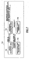
- Fig. 7 is a block diagram showing a hardware configuration of a performance calculation apparatus 700 of a downlink channel, to which the present invention is applied.
- a subdivision data holding unit 702 holds the transmission power Pi and traffic intensity Ai of each subdivision.
- a traffic calculating unit 704 calculates the mean Sm and variance Sv of the traffic at the base stations from the transmission power Pi and traffic intensity Ai.
- a performance calculating unit 706 calculates the performance such as the blocking probability and the probability of the degradation in the communication performance using the mean Sm and variance Sv calculated by the traffic calculating unit 704 and the threshold value T provided by a threshold value generator 708, and outputs them.
- the calculation of the performance using the calculated mean Sm and variance Sv, and the predetermined threshold value T can be carried out in various methods.
- the performance P can be calculated by the following equation using the complementary error function Erfc( ' ).
- Erfc( ' ) 1 2 ⁇ E r f c ⁇ T - Sm 2 S v
- T is the threshold value which can take the total maximum transmission power of the base stations or its constant multiple, for example.
- the method according to the present invention comprises a transmission power data storing step of storing transmission power data of the base stations corresponding to the subdivisions where the mobile stations are distributed and/or of the mobile stations visiting the subdivisions; a traffic intensity data storing step of storing traffic intensity data of the subdivisions; a traffic calculating step of calculating a mean and variance of applied traffic to the base stations; and a communication performance calculating step of calculating communication performance from the mean and variance.
- the traffic calculating step comprises a first calculating step of calculating, from the transmission power data of the mobile stations stored in the transmission power data storing step, received power at the base stations of signals sent from the mobile stations to the base stations; and a second calculating step of calculating, from the traffic intensity data stored in the traffic intensity data storing step and the received power, the mean and variance of the applied traffic at the base stations, thereby not only counting the interference traffic caused by communications carried out by the base stations of other subdivisions, but also counting as the traffic the interference power from the same radio channel reused by other subdivisions. This makes it possible to carry out accurate and simple calculation of the communication performance.
- the traffic calculating step comprises a third calculating step of calculating the mean and variance of the applied traffic at the base stations from the transmission power data of the base stations stored in the transmission power data storing step, and from the traffic intensity data stored in the traffic intensity data storing step, thereby taking account of the total downlink transmission power.
- the communication performance calculating step comprises a probability calculating step of calculating probability distribution from the mean and variance of the applied traffic; and a probability decision step of calculating a probability that the applied traffic exceeds a predetermined threshold value. This makes it possible to carry out accurate and simple calculation of the communication performance.
- the probability decision step comprises a step of setting acceptable interference power to the base stations or its constant multiple as the threshold value. This makes it possible to carry out highly accurate calculation of the communication performance.
- the probability decision step comprises a step of setting a sum of acceptable interference power to the base stations or its constant multiple and thermal noise power of receivers in base stations as the threshold value. This makes it possible to carry out highly accurate calculation of the communication performance.
- the probability decision step comprises a threshold value calculating step of carrying out calculation using a ratio of a sum of acceptable interference power to the base stations or its constant multiple and thermal noise power of receivers in the base stations to thermal noise power of the receivers; and a step of setting a calculation result in the threshold value calculating step as the threshold value.
- the probability decision step comprises a step of setting a total sum of maximum transmission powers of the base stations or its constant multiple as the threshold value. This makes it possible to carry out highly accurate calculation of the communication performance.
- Fig. 8 is a block diagram showing a hardware configuration of a blocking probability calculation apparatus of a first comparative example.
- the blocking probability calculation apparatus of the present example comprises a main controller 801, a storage 802, an input/output controller 803, an input unit 804, a display unit 805 and an output unit 806, which can consist of a personal computer, for example.
- the main controller 801 consists of a CPU, for example, and carries out comprehensive control of the entire system.
- the main controller 801 is connected with the storage 802.
- the storage 802 can consist of a hard disk, a flexible disk, an optical disk or the like.
- the main controller 801 is connected, through the input/output controller 803, with the input unit 804 such as a keyboard and a mouse, with the display unit 805 for displaying input data, calculation results and the like, and with the output unit 806 such as a printer for outputting the calculation results.
- the main controller 801 comprises an internal memory for storing its control program such as OS (Operating System), application programs such as calculating the blocking probability and data required, and carries out the calculation of the blocking probability using these programs.
- OS Operating System
- application programs such as calculating the blocking probability and data required, and carries out the calculation of the blocking probability using these programs.
- Fig. 9 is a block diagram illustrating functions of the blocking probability calculation apparatus of the present example.
- Fig. 10 is a flowchart illustrating a blocking probability calculation processing by the blocking probability calculation apparatus of the present example.
- the blocking probability calculation apparatus as shown in Fig. 9 comprises a dummy generator 901, an inverter 902, a multiplier 903, a blocking probability calculating unit 904 and a comparator 905.
- the blocking probability calculation apparatus receives the input with a load b on the communication system through the input unit 804 (step S1001). In the present example, it receives the applied traffic intensity as the load on the communication system.
- the dummy generator 901 generates the dummy pd (step S1002).
- a modified applied traffic intensity b' is calculated from the applied traffic intensity b using the generated dummy pd (step S1003).
- the blocking probability calculating unit 904 calculates the blocking probability p from the modified applied traffic intensity b' (step S1004).
- the blocking probability p is calculated using the method (formulae (1) and (2)) disclosed in the paper described above.
- the comparator 905 compares the dummy pd with the blocking probability p, and terminates the processing when the difference between the two is within a predetermined range, that is, when the two are considered to be equal (step S1005), in which case, it is considered that the sufficiently accurate blocking probability p is obtained.
- the modified applied traffic intensity b' (1 - pd) ⁇ b is considered equal to (1 - p) ⁇ b, which represents the applied traffic intensity taking account of the call loss. Accordingly, the blocking probability calculated from the modified applied traffic intensity b' can be considered accurate.
- the blocking probability p thus calculated is displayed on the display unit 805 as needed, and is output to the output unit 806.
- step S1005 a new dummy pd is generated from the compared result of the dummy pd with the calculated blocking probability p. More specifically, a new dummy pd is made larger than the current pd if p > pd, and is made smaller than the current pd if p ⁇ pd.
- step S1004 After that, the processing from step S1002 to step S1004 is iterated until the difference between the dummy pd and the blocking probability p falls within the predetermined range.
- the blocking probability calculation processing of the present example that is, the processing by the dummy generator 901, inverter 902, multiplier 903, blocking probability calculating unit 904 and comparator 905 is carried out by means of software (programs), it can be implemented by means of hardware.
- the program of the blocking probability calculation processing can be prestored in a floppy disk, CD-ROM or the like so that the program can be loaded onto a memory or hard disk before its execution.
- the applied traffic intensity is input as the load on the mobile communication system in the present example, the interference power, the transmission power of the base station or the like can be input instead.
- the calculation method disclosed in the paper described above is used for calculating the blocking probability, other calculation methods can be utilized.
- any system such as a fixed telephone communication system and a mobile communication system using an FDMA, TDMA or CDMA may be used, as long as it allows a plurality of users to carry out communications with sharing the resources, offering similar advantages.
- the second comparative example of the blocking probability calculation apparatus calculates the blocking probability of each factor when a plurality of factors are present which bring about a call loss, each.
- the hardware configuration of the present embodiment of the blocking probability calculation apparatus is the same as that of Fig. 8 .
- Fig. 11 is a diagram showing a case where a plurality of call loss factors are present.
- the blocking probabilities of switching machines 1101 and 1102 are p1 and p2, respectively, the blocking probability between A and B across the switching machines 1101 and 1102 is 1 - (1 - p1) ⁇ (1- p2).
- the modified applied traffic intensity between AC that is, the applied traffic intensity to the switching machine 1101
- the modified applied traffic intensity between BC that is, the applied traffic intensity to the switching machine 1102
- the modified applied traffic intensity between AC that is, the applied traffic intensity to the switching machine 1101
- the modified applied traffic intensity between BC that is, the applied traffic intensity to the switching machine 1102
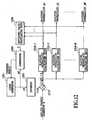
- Fig. 12 is a block diagram illustrating the functions of the blocking probability calculation apparatus of the present example
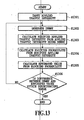
- Fig. 13 is a flowchart illustrating a blocking probability calculation processing of the present example.
- the blocking probability calculation apparatus as shown in Fig. 12 comprises a dummy generator 1201, an inverter 1202, a multiplier 1203, blocking probability calculating units 1204-1 - 1204-N, a comparator 1205 and an estimated value calculating unit 1206.
- steps S1301 - S1303 correspond to steps S1001 - S1003 in Fig. 10 of the second example.
- the blocking probabilities p1-pN are calculated using the method (formulae (1) and (2)) disclosed in the paper described above.
- the comparator 905 compares the dummy pd with the estimated value C, and terminates the processing when the difference between the two is within a predetermined range, that is, when the two are considered to be equal, in which case, it is considered that the sufficiently accurate blocking probabilities p1-pN are obtained.
- the blocking probabilities p1-pN thus calculated are displayed on the display unit 805 as needed, and are output to the output unit 806.
- step S1302 When the difference between the dummy pd and the estimated value C exceeds the predetermined range, the processing is returned to step S1302 (step S1306).
- step S1302 a new dummy pd is generated on the basis of the compared result of the dummy pd with the estimated value C. More specifically, a new dummy pd is made larger than the current pd if C > pd, and is made smaller than the current pd if C ⁇ pd.
- step S1305 the processing from step S1302 to step S1305 is iterated until the difference between the dummy pd and the estimated value C falls within the predetermined range.
- the blocking probability calculation processing of the present example that is, the processing by the dummy generator 1201, inverter 1202, multiplier 1203, blocking probability calculating units 1204-1 - 1204-N, comparator 1205 and the estimated value calculating unit 1206 is carried out by means of software (programs), it can be implemented by means of hardware.
- the program of the blocking probability calculation processing can be prestored in a floppy disk, CD-ROM or the like so that the program can be loaded onto a memory or hard disk before its execution.
- the applied traffic intensity is input as the load on the mobile communication system in the present example, the interference power, the transmission power of the base station or the like can be input instead.
- the calculation method disclosed in the paper described above is used for calculating the blocking probability, other calculation methods can be utilized.
- any system such as a fixed telephone communication system and a mobile communication system using an FDMA, TDMA or CDMA may be used, as long as it allows a plurality of users to carry out communications with sharing the resources, offering similar advantages.
Landscapes
- Engineering & Computer Science (AREA)
- Computer Networks & Wireless Communication (AREA)
- Signal Processing (AREA)
- Physics & Mathematics (AREA)
- Electromagnetism (AREA)
- Mobile Radio Communication Systems (AREA)
- Monitoring And Testing Of Transmission In General (AREA)
Claims (17)
- Kommunikationsperformanz-Berechnungsverfahren bei einem Mobilkommunikationssystem, das eine Vielzahl von Basisstationen und eine Vielzahl von Mobilstationen zur Durchführung einer Kommunikation mit den Basisstationen umfasst, wobei ein Bereich, wo die Mobilstationen verteilt sind, in eine Vielzahl von Unterteilungen aufgeteilt ist, dadurch gekennzeichnet, dass das Kommunikationsperformanz-Berechnungsverfahren aufweist:einen Sendeleistungsdaten-Speicherschritt des Speicherns von Sendeleistungsdaten einer der Unterteilung entsprechenden Basisstation, einer die Unterteilung besuchenden Mobilstation oder sowohl einer der Unterteilung entsprechenden Basisstation als auch einer die Unterteilung besuchenden Mobilstation für jede der Vielzahl von Unterteilungen;einen Verkehrswertdaten-Speicherschritt des Speicherns von Verkehrswertdaten der Unterteilung für jede der Vielzahl von Unterteilungen;einen Lastberechnungsschritt (S408; S506) des Berechnens eines Mittelwerts (Sm) und einer Varianz (Sv) einer Last an einer einzelnen Basisstation aus den Sendeleistungsdaten (Ri) und den Verkehrswertdaten (Ai) der Vielzahl von Unterteilungen; undeinen Kommunikationsperformanz-Berechnungsschritt des Berechnens einer Wahrscheinlichkeit, dass die Last einen vorbestimmten Schwellenwert überschreitet, aus dem Mittelwert und der Varianz.
- Kommunikationsperformanz-Berechnungsverfahren gemäß Anspruch 1, bei dem der Lastberechnungsschritt vornimmt:Berechnen einer Empfangsleistung von Signalen, die von den Mobilstationen an die einzelne Basisstation gesendet werden, an der einzelnen Basisstation aus den bei dem Sendeleistungsdaten-Speicherschritt gespeicherten Sendeleistungsdaten der Mobilstationen (S406); undBerechnen des Mittelwerts (Sm) und der Varianz (Sv) der Last an der einzelnen Basisstation aus den bei dem Verkehrswertdaten-Speicherschritt gespeicherten Verkehrswertdaten und der berechneten Empfangsleistung (S408).
- Kommunikationsperformanz-Berechnungsverfahren gemäß Anspruch 1, bei dem der Lastberechnungsschritt vornimmt:Berechnen des Mittelwerts und der Varianz der Last an der einzelnen Basisstation aus den bei dem Sendeleistungsdaten-Speicherschritt gespeicherten Sendeleistungsdaten der Basisstationen und aus den bei dem Verkehrswertdaten-Speicherschritt gespeicherten Verkehrswertdaten.
- Kommunikationsperformanz-Berechnungsverfahren gemäß Anspruch 1, bei dem der Kommunikationsperformanz-Berechnungsschritt aufweist:einen Wahrscheinlichkeitsberechnungsschritt des Berechnens einer Wahrscheinlichkeitsverteilung aus dem Mittelwert (Sm) und der Varianz (Sv) der Last; undeinen Wahrscheinlichkeitsbestimmungsschritt des Berechnens einer Wahrscheinlichkeit, dass die Last den vorbestimmten Schwellenwert überschreitet (S414).
- Kommunikationsperformanz-Berechnungsverfahren gemäß Anspruch 4, bei dem der Wahrscheinlichkeitsbestimmungsschritt einen Schritt des Einstellens einer für die einzelne Basisstation akzeptablen Interferenzleistung oder der mit einer Konstanten multiplizierten Interferenzleistung als den Schwellenwert aufweist.
- Kommunikationsperformanz-Berechnungsverfahren gemäß Anspruch 4, bei dem der Wahrscheinlichkeitsbestimmungsschritt einen Schritt des Einstellens einer Summe einer für die einzelne Basisstation akzeptablen Interferenzleistung oder der mit einer Konstanten multiplizierten Interferenzleistung und einer Wärmerauschleistung von Empfängern in der einzelnen Basisstation als den Schwellenwert aufweist.
- Kommunikationsperformanz-Berechnungsverfahren gemäß Anspruch 4, bei dem der Wahrscheinlichkeitsbestimmungsschritt aufweist:einen Schwellenwertberechnungsschritt des Durchführens einer Berechnung unter Verwendung eines Verhältnisses einer Summe einer für die einzelne Basisstation akzeptablen Interferenzleistung oder der mit einer Konstanten multiplizierten Interferenzleistung und einer Wärmerauschleistung von Empfängern in der einzelnen Basisstation zur Wärmerauschleistung der Empfänger; undeinen Schritt des Einstellens eines Berechnungsergebnisses in dem Schwellenwertberechnungsschritt als den Schwellenwert.
- Kommunikationsperformanz-Berechnungsverfahren gemäß Anspruch 4, bei dem der Wahrscheinlichkeitsbestimmungsschritt einen Schritt des Einstellens einer Gesamtsumme von maximalen Sendeleistungen der Basisstationen oder der mit einer Konstanten multiplizierten Gesamtsumme als den Schwellenwert aufweist.
- Computer-lesbares Aufzeichnungsmedium, das ein Programm speichert, das einen Computer veranlasst, ein Kommunikationsperformanz-Berechnungsverfahren bei einem Mobilkommunikationssystem auszuführen, das eine Vielzahl von Basisstationen und eine Vielzahl von Mobilstationen zur Durchführung einer Kommunikation mit den Basisstationen umfasst, wobei ein Bereich, wo die Mobilstationen verteilt sind, in eine Vielzahl von Unterteilungen aufgeteilt ist, dadurch gekennzeichnet, dass das Kommunikationsperformanz-Berechnungsverfahren aufweist:einen Sendeleistungsdaten-Speicherschritt des Speicherns von Sendeleistungsdaten einer der Unterteilung entsprechenden Basisstation, einer die Unterteilung besuchenden Mobilstation oder sowohl einer der Unterteilung entsprechenden Basisstation als auch einer die Unterteilung besuchenden Mobilstation für jede der Vielzahl von Unterteilungen;einen Verkehrswertdaten-Speicherschritt des Speicherns von Verkehrswertdaten der Unterteilung für jede der Vielzahl von Unterteilungen;einen Lastberechnungsschritt (S408; S506) des Berechnens eines Mittelwerts (Sm) und einer Varianz (Sv) einer Last an einer einzelnen Basisstation aus den Sendeleistungsdaten (Ri) und den Verkehrswertdaten (Ai) der Vielzahl von Unterteilungen; undeinen Kommunikationsperformanz-Berechnungsschritt des Berechnens einer Wahrscheinlichkeit, dass die Last einen vorbestimmten Schwellenwert überschreitet, aus dem Mittelwert und der Varianz.
- Kommunikationsperformanz-Berechnungsvorrichtung bei einem Mobilkommunikationssystem, das eine Vielzahl von Basisstationen und eine Vielzahl von Mobilstationen zur Durchführung einer Kommunikation mit den Basisstationen umfasst, wobei ein Bereich, wo die Mobilstationen verteilt sind, in eine Vielzahl von Unterteilungen aufgeteilt ist, dadurch gekennzeichnet, dass die Kommunikationsperformanz-Berechnungsvorrichtung aufweist:eine Sendeleistungsdaten-Speichereinrichtung (602; 702) zum Speichern von Sendeleistungsdaten einer der Unterteilung entsprechenden Basisstation, einer die Unterteilung besuchenden Mobilstation oder sowohl einer der Unterteilung entsprechenden Basisstation als auch einer die Unterteilung besuchenden Mobilstation für jede der Vielzahl von Unterteilungen;eine Verkehrswertdaten-Speichereinrichtung zum Speichern von Verkehrswertdaten der Unterteilung für jede der Vielzahl von Unterteilungen;eine Lastberechnungseinrichtung (606; 608; 704) zum Berechnen eines Mittelwerts (Sm) und einer Varianz (Sv) einer Last an einer einzelnen Basisstation aus den Sendeleistungsdaten (Ri) und den Verkehrswertdaten (Ai) der Vielzahl von Unterteilungen; undeine Kommunikationsperformanz-Berechnungseinrichtung (610) zum Berechnen einer Wahrscheinlichkeit, dass die Last einen vorbestimmten Schwellenwert überschreitet, aus dem Mittelwert und der Varianz.
- Kommunikationsperformanz-Berechnungsvorrichtung gemäß Anspruch 10, bei der die Lastberechnungseinrichtung vornimmt:Berechnen (606) einer Empfangsleistung von Signalen, die von den Mobilstationen an die einzelne Basisstation gesendet werden, an der einzelnen Basisstation aus den durch die Sendeleistungsdaten-Speichereinrichtung gespeicherten Sendeleistungsdaten der Mobilstationen; undBerechnen (608) des Mittelwerts und der Varianz der Last an der einzelnen Basisstation aus den durch die Verkehrswertdaten-Speichereinrichtung gespeicherten Verkehrswertdaten und der berechneten Empfangsleistung.
- Kommunikationsperformanz-Berechnungsvorrichtung gemäß Anspruch 10, bei der die Lastberechnungseinrichtung vornimmt:Berechnen (704) des Mittelwerts und der Varianz der Last an der einzelnen Basisstation aus den durch die Sendeleistungsdaten-Speichereinrichtung gespeicherten Sendeleistungsdaten der Basisstationen und aus den durch die Verkehrswertdaten-Speichereinrichtung gespeicherten Verkehrswertdaten.
- Kommunikationsperformanz-Berechnungsvorrichtung gemäß Anspruch 10, bei der die Kommunikationsperformanz-Berechnungseinrichtung aufweist:eine Wahrscheinlichkeitsberechnungseinrichtung (610; 706) zum Berechnen einer Wahrscheinlichkeitsverteilung aus dem Mittelwert und der Varianz der Last; undeine Wahrscheinlichkeitsbestimmungseinrichtung zum Berechnen der Wahrscheinlichkeit, dass die Last den vorbestimmten Schwellenwert (T) überschreitet.
- Kommunikationsperformanz-Berechnungsvorrichtung gemäß Anspruch 13, bei der die Wahrscheinlichkeitsbestimmungseinrichtung eine Einrichtung zum Einstellen einer für die einzelne Basisstation akzeptablen Interferenzleistung oder der mit einer Konstanten multiplizierten Interferenzleistung als den Schwellenwert (612; 708) aufweist.
- Kommunikationsperformanz-Berechnungsvorrichtung gemäß Anspruch 13, bei der die Wahrscheinlichkeitsbestimmungseinrichtung eine Einrichtung zum Einstellen einer Summe einer für die einzelne Basisstation akzeptablen Interferenzleistung oder der mit einer Konstanten multiplizierten Interferenzleistung und einer Wärmerauschleistung von Empfängern in der einzelnen Basisstation als den Schwellenwert (612; 708) aufweist.
- Kommunikationsperformanz-Berechnungsvorrichtung gemäß Anspruch 13, bei der die Wahrscheinlichkeitsbestimmungseinrichtung aufweist:eine Schwellenwertberechnungseinrichtung (612) zum Durchführen einer Berechnung unter Verwendung eines Verhältnisses einer Summe einer für die einzelne Basisstation akzeptablen Interferenzleistung oder der mit einer Konstanten multiplizierten Interferenzleistung und einer Wärmerauschleistung von Empfängern in der einzelnen Basisstation zur Wärmerauschleistung der Empfänger; undeine Einrichtung zum Einstellen eines Berechnungsergebnisses durch die Schwellenwertberechnungseinrichtung als den Schwellenwert.
- Kommunikationsperformanz-Berechnungsvorrichtung gemäß Anspruch 13, bei der die Wahrscheinlichkeitsbestimmungseinrichtung (706) eine Einrichtung zum Einstellen einer Gesamtsumme von maximalen Sendeleistungen der Basisstationen oder der mit einer Konstanten multiplizierten Gesamtsumme als den Schwellenwert aufweist.
Priority Applications (1)
| Application Number | Priority Date | Filing Date | Title |
|---|---|---|---|
| EP03077512A EP1381247A1 (de) | 1999-08-20 | 2000-08-11 | Verfahren zur Blockierungswahrscheinlichkeitsrechnung |
Applications Claiming Priority (4)
| Application Number | Priority Date | Filing Date | Title |
|---|---|---|---|
| JP23479999 | 1999-08-20 | ||
| JP23479999A JP3678948B2 (ja) | 1999-08-20 | 1999-08-20 | 通信システムにおける呼損率計算方法および呼損率計算装置ならびに記録媒体 |
| JP2000027990A JP3479484B2 (ja) | 2000-02-04 | 2000-02-04 | 移動通信システムの通信品質計算方法および通信品質計算装置 |
| JP2000027990 | 2000-02-04 |
Related Child Applications (1)
| Application Number | Title | Priority Date | Filing Date |
|---|---|---|---|
| EP03077512A Division EP1381247A1 (de) | 1999-08-20 | 2000-08-11 | Verfahren zur Blockierungswahrscheinlichkeitsrechnung |
Publications (3)
| Publication Number | Publication Date |
|---|---|
| EP1079646A2 EP1079646A2 (de) | 2001-02-28 |
| EP1079646A3 EP1079646A3 (de) | 2002-09-04 |
| EP1079646B1 true EP1079646B1 (de) | 2008-06-04 |
Family
ID=26531764
Family Applications (2)
| Application Number | Title | Priority Date | Filing Date |
|---|---|---|---|
| EP03077512A Withdrawn EP1381247A1 (de) | 1999-08-20 | 2000-08-11 | Verfahren zur Blockierungswahrscheinlichkeitsrechnung |
| EP00306879A Expired - Lifetime EP1079646B1 (de) | 1999-08-20 | 2000-08-11 | Verfahren, Einrichtung in einem mobilen Übertragungssystem und Aufzeichnungsmedium zur Übertragungsleistungsrechnung und zur Blockierungswahrscheinlichkeitsrechnung |
Family Applications Before (1)
| Application Number | Title | Priority Date | Filing Date |
|---|---|---|---|
| EP03077512A Withdrawn EP1381247A1 (de) | 1999-08-20 | 2000-08-11 | Verfahren zur Blockierungswahrscheinlichkeitsrechnung |
Country Status (5)
| Country | Link |
|---|---|
| EP (2) | EP1381247A1 (de) |
| KR (2) | KR100380326B1 (de) |
| CN (2) | CN1160985C (de) |
| AU (1) | AU773392B2 (de) |
| DE (1) | DE60039093D1 (de) |
Families Citing this family (9)
| Publication number | Priority date | Publication date | Assignee | Title |
|---|---|---|---|---|
| GB2378853B (en) * | 2001-08-14 | 2003-07-16 | Lucent Technologies Inc | A method of determining an estimate of the probability of a user terminal being blocked from making a call-connection to a base station |
| JP4154174B2 (ja) * | 2002-05-20 | 2008-09-24 | 株式会社エヌ・ティ・ティ・ドコモ | トラフィック量測定装置、トラフィック量測定方法及びトラフィック量測定プログラム |
| JP2005117357A (ja) * | 2003-10-08 | 2005-04-28 | Nec Corp | 無線通信システムの管理方法及びシステム並びに管理装置 |
| US8457552B1 (en) | 2004-01-20 | 2013-06-04 | Qualcomm Incorporated | Method and apparatus for reduced complexity short range wireless communication system |
| CN1954529B (zh) * | 2004-08-05 | 2011-03-02 | 中兴通讯股份有限公司 | 宽带码分多址系统上行链路的业务折算方法 |
| US7684464B2 (en) | 2004-12-21 | 2010-03-23 | Qualcomm Incorporated | Method and apparatus for performing channel assessment in a wireless communication system |
| JP4463189B2 (ja) | 2005-11-22 | 2010-05-12 | Nec東芝スペースシステム株式会社 | 探索機能付きモバイル装置 |
| KR101348033B1 (ko) * | 2007-09-21 | 2014-01-03 | 주식회사 케이티 | 기지국 관리 시스템에서 이기종 기지국 시스템 간의 간섭분석 방법 |
| KR102374522B1 (ko) * | 2021-09-13 | 2022-03-15 | (주)프레스토테크놀로지 | 거래 위험 관리를 지원하는 거래소 운영 방법 및 시스템 |
Family Cites Families (6)
| Publication number | Priority date | Publication date | Assignee | Title |
|---|---|---|---|---|
| ES2072428T3 (es) * | 1989-03-03 | 1995-07-16 | Telia Ab | Metodo para planificacion de celdas de radio. |
| US5732328A (en) * | 1995-04-25 | 1998-03-24 | Lucent Technologies Inc. | Method for power control in wireless networks for communicating multiple information classes |
| US5838671A (en) * | 1995-06-23 | 1998-11-17 | Ntt Mobile Communications Network Inc. | Method and apparatus for call admission control in CDMA mobile communication system |
| FI964707A (fi) * | 1996-11-26 | 1998-05-27 | Nokia Telecommunications Oy | Menetelmä kuormituksen kontrolloimiseksi ja radiojärjestelmä |
| CN1200585A (zh) * | 1997-05-22 | 1998-12-02 | 张旭俊 | 三相互不相扰配电变压器、开关组合装置 |
| US6097957A (en) * | 1997-11-14 | 2000-08-01 | Motorola, Inc. | Radiotelephone service planning system and method for determining a best server for a communication connection |
-
2000
- 2000-08-11 DE DE60039093T patent/DE60039093D1/de not_active Expired - Lifetime
- 2000-08-11 EP EP03077512A patent/EP1381247A1/de not_active Withdrawn
- 2000-08-11 EP EP00306879A patent/EP1079646B1/de not_active Expired - Lifetime
- 2000-08-17 AU AU53447/00A patent/AU773392B2/en not_active Ceased
- 2000-08-18 CN CNB001241737A patent/CN1160985C/zh not_active Expired - Lifetime
- 2000-08-18 CN CNB031367429A patent/CN1220396C/zh not_active Expired - Fee Related
- 2000-08-19 KR KR10-2000-0048182A patent/KR100380326B1/ko not_active IP Right Cessation
-
2002
- 2002-07-24 KR KR10-2002-0043668A patent/KR100395599B1/ko not_active IP Right Cessation
Also Published As
| Publication number | Publication date |
|---|---|
| CN1285701A (zh) | 2001-02-28 |
| KR20020067467A (ko) | 2002-08-22 |
| DE60039093D1 (de) | 2008-07-17 |
| CN1479537A (zh) | 2004-03-03 |
| KR100395599B1 (ko) | 2003-08-25 |
| KR100380326B1 (ko) | 2003-04-16 |
| CN1220396C (zh) | 2005-09-21 |
| EP1079646A3 (de) | 2002-09-04 |
| AU773392B2 (en) | 2004-05-27 |
| CN1160985C (zh) | 2004-08-04 |
| KR20010050138A (ko) | 2001-06-15 |
| EP1079646A2 (de) | 2001-02-28 |
| EP1381247A1 (de) | 2004-01-14 |
| AU5344700A (en) | 2001-02-22 |
Similar Documents
| Publication | Publication Date | Title |
|---|---|---|
| US7672672B2 (en) | Methods and techniques for penalty-based channel assignments in a cellular network | |
| JP5027814B2 (ja) | セル式移動通信網を計画する方法 | |
| US6442397B1 (en) | Method for self-calibration of a wireless communication system | |
| US7002920B1 (en) | Capacity enhancement for multi-code CDMA with integrated services through quality of service and admission control | |
| US7330723B2 (en) | Communication performance calculation method and communication performance calculation apparatus in mobile communication system, and blocking probability calculation method and blocking probability calculation apparatus in communication system, and recording medium | |
| US7725108B2 (en) | Method and system for planning the power of carriers in a cellular telecommunications network | |
| CN101352059B (zh) | 用于规划蜂窝移动电信网络的方法 | |
| Luna et al. | ACO vs EAs for solving a real-world frequency assignment problem in GSM networks | |
| EP1178694A1 (de) | Verfahren und Vorrichtung zum Entwurf, Anpassung oder Betreiben von drahtlosen Netzwerken durch Optimierung einer Anfangs-Frequenzzuordnung | |
| EP1079646B1 (de) | Verfahren, Einrichtung in einem mobilen Übertragungssystem und Aufzeichnungsmedium zur Übertragungsleistungsrechnung und zur Blockierungswahrscheinlichkeitsrechnung | |
| US6925066B1 (en) | Methods and apparatus for design, adjustment or operation of wireless networks using multi-stage optimization | |
| JP3848923B2 (ja) | (cdma)無線網におけるセル容量の計画及び/または評価のための方法及びシステム | |
| US7653395B2 (en) | Computer implemented methods and computer program products for evaluating radio communications systems | |
| US7336957B2 (en) | System and method for simulation of performance of measurement-based algorithms for slotted wireless communications | |
| US6512933B1 (en) | Iterative system and method for optimizing CDMA load distribution using reverse interference measurements | |
| AU2004201258B2 (en) | Blocking Probability Calculation Method and Blocking Probability Calculation Apparatus in a Communication System | |
| JP3479484B2 (ja) | 移動通信システムの通信品質計算方法および通信品質計算装置 | |
| Khoshkholgh et al. | Cell association in dense heterogeneous cellular networks | |
| Pu et al. | Novel fast user-placement ushering algorithms for indoor femtocell networks | |
| EP1804542A1 (de) | Modellierung von abwärtsgerichteter Systembelastung | |
| Hasselbach et al. | Performance evaluation of self-optimising mobile radio networks in realistic scenarios | |
| Geerdes et al. | Efficient Approximation of Blocking Rates in UMTS Radio Networks |
Legal Events
| Date | Code | Title | Description |
|---|---|---|---|
| PUAI | Public reference made under article 153(3) epc to a published international application that has entered the european phase |
Free format text: ORIGINAL CODE: 0009012 |
|
| AK | Designated contracting states |
Kind code of ref document: A2 Designated state(s): AT BE CH CY DE DK ES FI FR GB GR IE IT LI LU MC NL PT SE |
|
| AX | Request for extension of the european patent |
Free format text: AL;LT;LV;MK;RO;SI |
|
| PUAL | Search report despatched |
Free format text: ORIGINAL CODE: 0009013 |
|
| AK | Designated contracting states |
Kind code of ref document: A3 Designated state(s): AT BE CH CY DE DK ES FI FR GB GR IE IT LI LU MC NL PT SE |
|
| AX | Request for extension of the european patent |
Free format text: AL;LT;LV;MK;RO;SI |
|
| 17P | Request for examination filed |
Effective date: 20030130 |
|
| AKX | Designation fees paid |
Designated state(s): DE GB |
|
| 17Q | First examination report despatched |
Effective date: 20030409 |
|
| GRAP | Despatch of communication of intention to grant a patent |
Free format text: ORIGINAL CODE: EPIDOSNIGR1 |
|
| GRAS | Grant fee paid |
Free format text: ORIGINAL CODE: EPIDOSNIGR3 |
|
| GRAA | (expected) grant |
Free format text: ORIGINAL CODE: 0009210 |
|
| AK | Designated contracting states |
Kind code of ref document: B1 Designated state(s): DE GB |
|
| REG | Reference to a national code |
Ref country code: GB Ref legal event code: FG4D |
|
| REF | Corresponds to: |
Ref document number: 60039093 Country of ref document: DE Date of ref document: 20080717 Kind code of ref document: P |
|
| PLBE | No opposition filed within time limit |
Free format text: ORIGINAL CODE: 0009261 |
|
| STAA | Information on the status of an ep patent application or granted ep patent |
Free format text: STATUS: NO OPPOSITION FILED WITHIN TIME LIMIT |
|
| 26N | No opposition filed |
Effective date: 20090305 |
|
| PGFP | Annual fee paid to national office [announced via postgrant information from national office to epo] |
Ref country code: DE Payment date: 20130807 Year of fee payment: 14 |
|
| PGFP | Annual fee paid to national office [announced via postgrant information from national office to epo] |
Ref country code: GB Payment date: 20130807 Year of fee payment: 14 |
|
| REG | Reference to a national code |
Ref country code: DE Ref legal event code: R119 Ref document number: 60039093 Country of ref document: DE |
|
| REG | Reference to a national code |
Ref country code: DE Ref legal event code: R079 Ref document number: 60039093 Country of ref document: DE Free format text: PREVIOUS MAIN CLASS: H04Q0007340000 Ipc: H04W0024000000 |
|
| GBPC | Gb: european patent ceased through non-payment of renewal fee |
Effective date: 20140811 |
|
| REG | Reference to a national code |
Ref country code: DE Ref legal event code: R079 Ref document number: 60039093 Country of ref document: DE Free format text: PREVIOUS MAIN CLASS: H04Q0007340000 Ipc: H04W0024000000 Effective date: 20150427 Ref country code: DE Ref legal event code: R119 Ref document number: 60039093 Country of ref document: DE Effective date: 20150303 |
|
| PG25 | Lapsed in a contracting state [announced via postgrant information from national office to epo] |
Ref country code: DE Free format text: LAPSE BECAUSE OF NON-PAYMENT OF DUE FEES Effective date: 20150303 Ref country code: GB Free format text: LAPSE BECAUSE OF NON-PAYMENT OF DUE FEES Effective date: 20140811 |