EP1079554A2 - Funkempfangstester - Google Patents
Funkempfangstester Download PDFInfo
- Publication number
- EP1079554A2 EP1079554A2 EP00116685A EP00116685A EP1079554A2 EP 1079554 A2 EP1079554 A2 EP 1079554A2 EP 00116685 A EP00116685 A EP 00116685A EP 00116685 A EP00116685 A EP 00116685A EP 1079554 A2 EP1079554 A2 EP 1079554A2
- Authority
- EP
- European Patent Office
- Prior art keywords
- signal
- radio
- noise ratio
- radio signal
- reception
- Prior art date
- Legal status (The legal status is an assumption and is not a legal conclusion. Google has not performed a legal analysis and makes no representation as to the accuracy of the status listed.)
- Withdrawn
Links
- 230000005670 electromagnetic radiation Effects 0.000 claims abstract 2
- 238000011161 development Methods 0.000 description 2
- 230000018109 developmental process Effects 0.000 description 2
- 230000007547 defect Effects 0.000 description 1
- 238000010586 diagram Methods 0.000 description 1
- 238000011156 evaluation Methods 0.000 description 1
Images
Classifications
-
- H—ELECTRICITY
- H04—ELECTRIC COMMUNICATION TECHNIQUE
- H04B—TRANSMISSION
- H04B17/00—Monitoring; Testing
- H04B17/30—Monitoring; Testing of propagation channels
- H04B17/309—Measuring or estimating channel quality parameters
- H04B17/336—Signal-to-interference ratio [SIR] or carrier-to-interference ratio [CIR]
Definitions
- the innovation concerns a device for measuring the reception quality of one for radio clocks certain time signal radio signal according to the preamble of claim 1.
- Radio clocks More and more utility clocks, but also time switches are nowadays used as radio controlled clocks manufactured. These have an antenna and a radio receiver with which the time signal radio signal from the long-wave transmitter DCF 77, located near Frankfurt stands on the Main and sends, receives with a range of over 1,500km can. The date and especially the current one is from the signal of this transmitter To determine the time precisely to the second. Radio clocks always show the right one Time and pose z. B. also automatically from winter to summer time.
- Radio shading or interference from a variety of electrical devices can receive of the time signal radio signal so that proper operation the radio clocks is not possible.
- reception testers are known in which the field strength of the received Radio signal is displayed. This will result in an analog output from the receiver used a so-called field strength proportional (RSSI: relative signal strength indicator) provides.
- RSSI relative signal strength indicator
- the disadvantage of this reception tester is that alone the size of the field strength of the received signal is displayed, regardless whether there is a disturbance (e.g. from television, computer, data line, jammer, disturbing defect devices), which delivers field strength, but the time signal radio signal disturbing or even illegible. So these are reception testers not well suited for measuring the quality of the time signal radio reception.
- the innovation is based on the task propose a radio reception tester that measures the reception quality of the time signal radio signal measures and displays.
- the proposed radio reception tester has one in addition to the receiver Signal processing stage that analyzes the time signal demodulated by the receiver and from this the signal-to-noise ratio is determined.
- This signal-to-noise ratio is a measure of the quality of the radio signal received and is displayed by suitable display means.
- the signal processing stage is preferably formed by a microprocessor.
- the demodulated radio signal in the signal processing stage with an ideal target signal, which in one Memory is stored, and from this comparison the signal-to-noise ratio of the received radio signal.
- the display means are designed so that the signal-to-noise ratio displayed in an analog and / or multi-level digital display becomes.
- the display means are preferably formed by a plurality of light-emitting diodes, with good reception all LEDs light up, but the less LEDs light up the poorer the radio reception is. It is preferred provided that the good reception LEDs green, the poor reception indicating yellow and the bad or none at all Send out dead light indicating reception.
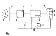
- An antenna 1 receives the time signal radio signals 2 from the long-wave transmitter, not shown DCF 77.
- the received radio signal reaches a receiver 3.
- a radio signal is received when a (green) LED lights up 4 is displayed.
- the radio signal is demodulated in the receiver 3.
- the demodulated time signal arrives in a microprocessor 5, which acts as a signal processing stage serves.
- the microprocessor 5 has a non-volatile memory 6, in which an ideal target signal is stored. With this ideal target signal the demodulated time signal is compared and from this comparison the signal-to-noise ratio of the received time signal. Find these events in the microprocessor 5 instead.
- the microprocessor 5 in the display unit 7 controls several light-emitting diodes 8, 9 and 10 differently. This control takes place in such a way that in the event of very poor or unreadable "reception only the red LED 10 burns, whereas in the case of poor reception, in which bit errors would occur in the evaluation of the time signal, one or both yellow LEDs 9 additionally light up and, if the reception is satisfactory to very good, one or all green ones Light-emitting diodes 8 light up. In this way, the quality of the received time signal radio signal can be displayed in six stages.
- the electrical energy required to operate the radio reception tester provides a battery 11 with which the receiver 3, the microprocessor 5 and the display unit 7 are connected via power lines 12. Furthermore, there is a switch 13 provided with which the radio reception tester is put into operation. This Switch is designed as a pressure switch, so that the radio reception tester is only so remains on for a long time as switch 13 is pressed.
Landscapes
- Engineering & Computer Science (AREA)
- Quality & Reliability (AREA)
- Physics & Mathematics (AREA)
- Electromagnetism (AREA)
- Computer Networks & Wireless Communication (AREA)
- Signal Processing (AREA)
- Monitoring And Testing Of Transmission In General (AREA)
- Electric Clocks (AREA)
Abstract
Description

Claims (5)
- Gerät zur Messung der Empfangsqualität eines für Funkuhren bestimmten Zeitzeichen-Funksignals, wobei das Gerät batteriebetrieben ist und eine elektromagnetische Strahlung aufnehmende Antenne sowie einen ein elektromagnetisches Funksignal demodulierenden Empfänger aufweist,
dadurch gekennzeichnet,
daß in dem Gerät eine Signalverarbeitungsstufe, in der das Signal-zu-Rausch-Verhältnis und/oder Signal-zu-Störungs-Verhältnis des demodulierten Funksignals ermittelbar ist, und Anzeigemittel (7), durch die die Qualität des empfangenen Funksignals in Form des Signal-zu-Rausch-Verhältnisses anzeigbar ist, vorgesehen sind. - Gerät nach Anspruch 1,
dadurch gekennzeichnet,
daß die Signalverarbeitungsstufe durch einen Microprozessor (5) gebildet ist, in dem das demodulierte Funksignal analysierbar ist. - Gerät nach Anspruch 1 oder 2,
dadurch gekennzeichnet,
daß in der Signalverarbeitungsstufe das demodulierte Funksignal mit einem in einem Speicher (6) hinterlegten, idealen Soll-Signal vergleichbar und daraus das Signal-zu-Rausch-Verhältnis des empfangenen Funksignals bestimmbar ist. - Gerät nach einem der Ansprüche 1 bis 3,
dadurch gekennzeichnet,
daß die Anzeigemittel (7) so ausgeführt sind, daß das Signal-zu-Rausch-Verhältnis in einer analogen und/oder mehrstufigen digitalen Anzeige anzeigbar ist. - Gerät nach einem der vorhergehenden Ansprüche,
dadurch gekennzeichnet,
daß die Anzeigemittel (7) durch mehrere Leuchtdioden (8, 9, 10) gebildet sind, wobei bei schlechtem oder nicht vorhandenen Funkempfang nur eine, vorzugsweise rote (10), oder gar keine Leuchtdiode leuchtet, aber desto mehr, vorzugsweise zusätzlich gelbe (9) und grüne (8) Leuchtdioden leuchten, je besser der Funkempfang ist.
Applications Claiming Priority (2)
| Application Number | Priority Date | Filing Date | Title |
|---|---|---|---|
| DE29914606U DE29914606U1 (de) | 1999-08-20 | 1999-08-20 | Funkempfangstester |
| DE29914606U | 1999-08-20 |
Publications (2)
| Publication Number | Publication Date |
|---|---|
| EP1079554A2 true EP1079554A2 (de) | 2001-02-28 |
| EP1079554A3 EP1079554A3 (de) | 2003-09-10 |
Family
ID=8077790
Family Applications (1)
| Application Number | Title | Priority Date | Filing Date |
|---|---|---|---|
| EP00116685A Withdrawn EP1079554A3 (de) | 1999-08-20 | 2000-08-02 | Funkempfangstester |
Country Status (3)
| Country | Link |
|---|---|
| EP (1) | EP1079554A3 (de) |
| DE (1) | DE29914606U1 (de) |
| PL (1) | PL342075A1 (de) |
Cited By (6)
| Publication number | Priority date | Publication date | Assignee | Title |
|---|---|---|---|---|
| DE102004004416A1 (de) * | 2004-01-29 | 2005-08-18 | Atmel Germany Gmbh | Verfahren zur Ermittlung der Signalgüte eines gesendeten Zeitzeichensignals |
| US7317905B2 (en) | 2004-01-29 | 2008-01-08 | Atmel Germany Gmbh | Radio-controlled clock and method for gaining time information |
| US7333467B2 (en) | 2003-12-08 | 2008-02-19 | Atmel Germany Gmbh | Receiver circuit and method using selectively variable amplification for receiving time signals from different transmitters |
| US7369628B2 (en) | 2004-01-29 | 2008-05-06 | Atmel Germany Gmbh | Method for gaining time information and receiver for implementing the method |
| US7486657B2 (en) | 2003-07-31 | 2009-02-03 | Atmel Germany Gmbh | Radio controlled clock and method for retrieving time information from time signals |
| CN109547130A (zh) * | 2018-12-12 | 2019-03-29 | 中国人民解放军陆军工程大学 | 带外电磁辐射二阶互调低频阻塞效应预测方法及设备 |
Family Cites Families (3)
| Publication number | Priority date | Publication date | Assignee | Title |
|---|---|---|---|---|
| DE3015312A1 (de) * | 1980-04-21 | 1981-10-22 | Wolfgang Dr.-Ing. 6101 Groß-Bieberau Hilberg | Qualitaetsindikator fuer den empfang bei funkuhren |
| DE3101406A1 (de) * | 1981-01-17 | 1983-01-05 | Wolfgang Dr.-Ing. 6101 Groß-Bieberau Hilberg | Automatische funkuhranpassung |
| DE3719650A1 (de) * | 1987-06-12 | 1988-12-22 | Forschungsgesellschaft Fuer Fe | Regelung fuer funkzeitzeichenempfaenger |
-
1999
- 1999-08-20 DE DE29914606U patent/DE29914606U1/de not_active Expired - Lifetime
-
2000
- 2000-08-02 EP EP00116685A patent/EP1079554A3/de not_active Withdrawn
- 2000-08-18 PL PL00342075A patent/PL342075A1/xx unknown
Cited By (6)
| Publication number | Priority date | Publication date | Assignee | Title |
|---|---|---|---|---|
| US7486657B2 (en) | 2003-07-31 | 2009-02-03 | Atmel Germany Gmbh | Radio controlled clock and method for retrieving time information from time signals |
| US7333467B2 (en) | 2003-12-08 | 2008-02-19 | Atmel Germany Gmbh | Receiver circuit and method using selectively variable amplification for receiving time signals from different transmitters |
| DE102004004416A1 (de) * | 2004-01-29 | 2005-08-18 | Atmel Germany Gmbh | Verfahren zur Ermittlung der Signalgüte eines gesendeten Zeitzeichensignals |
| US7317905B2 (en) | 2004-01-29 | 2008-01-08 | Atmel Germany Gmbh | Radio-controlled clock and method for gaining time information |
| US7369628B2 (en) | 2004-01-29 | 2008-05-06 | Atmel Germany Gmbh | Method for gaining time information and receiver for implementing the method |
| CN109547130A (zh) * | 2018-12-12 | 2019-03-29 | 中国人民解放军陆军工程大学 | 带外电磁辐射二阶互调低频阻塞效应预测方法及设备 |
Also Published As
| Publication number | Publication date |
|---|---|
| DE29914606U1 (de) | 2000-12-28 |
| PL342075A1 (en) | 2001-02-26 |
| EP1079554A3 (de) | 2003-09-10 |
Similar Documents
| Publication | Publication Date | Title |
|---|---|---|
| DE60026823T2 (de) | Instrumentengehause fur elektronischen elektrizitaetszaehler | |
| DE3329507A1 (de) | Automatisiertes ueberwachungsgeraet fuer die verteilung elektrischer energie mit verbesserter darstellungseinrichtung | |
| DE3139002A1 (de) | Diversity-empfaenger | |
| DE19780948B4 (de) | Kombinierte elektronische Uhr | |
| DE102014112033B4 (de) | Elektrische Messvorrichtung mit Codierungseinheit zur Erzeugung von QR-Codes | |
| DE69203446T2 (de) | Verfahren und vorrichtung zur determination von gruppen. | |
| EP1079554A2 (de) | Funkempfangstester | |
| DE2844111A1 (de) | Loran-c-empfaenger | |
| DE2643250B2 (de) | Zentralgesteuerte Uhr | |
| DE3015312A1 (de) | Qualitaetsindikator fuer den empfang bei funkuhren | |
| DE102005027914B4 (de) | Einrichtung zum Steuern der Stromversorgung eines Mobilgeräts sowie Mobilgerät, insbesondere Kamera | |
| DE1902049U (de) | Tragbares fernsehempfangsgeraet mit messvorrichtung. | |
| DE4426509C2 (de) | Einrichtung zur Anzeige der elektrischen Verbrauchsdaten eines Verbrauchers | |
| DE3933222A1 (de) | Messeinrichtung | |
| DE3687418T2 (de) | Einrichtung zum pruefen einer alarmschaltung. | |
| DE29620142U1 (de) | System | |
| DE2100490A1 (de) | Fernmeßsystem mit einem kontinuier hch überwachenden Kodierer | |
| DE4335640C2 (de) | Anordnung für Funkrundsteuerempfänger in Lichtmasten | |
| DE10305974B3 (de) | Apparat zur Anzeige von sich ändernden Messwerten | |
| DE20221914U1 (de) | Klimaanlage mit einem Fernbedienungselement | |
| DE20310318U1 (de) | Vorrichtung zur Auf- und/oder Entladung eines elektrischen Energiespeichers | |
| EP2114082A1 (de) | Sensor und/oder Aktor mit Mitteln zur energieeffizienten drahtlosen Kommunikation von Daten | |
| Pawan | Election Commission of India | |
| DE3331403A1 (de) | Mikroprozessorgesteuertes elektronisches geraet | |
| EP1233518A2 (de) | Schnittstellenanordnung für elektronische Geräte |
Legal Events
| Date | Code | Title | Description |
|---|---|---|---|
| PUAI | Public reference made under article 153(3) epc to a published international application that has entered the european phase |
Free format text: ORIGINAL CODE: 0009012 |
|
| AK | Designated contracting states |
Kind code of ref document: A2 Designated state(s): AT BE CH CY DE DK ES FI FR GB GR IE IT LI LU MC NL PT SE |
|
| AX | Request for extension of the european patent |
Free format text: AL;LT;LV;MK;RO;SI |
|
| RAP1 | Party data changed (applicant data changed or rights of an application transferred) |
Owner name: DIEHL AKO STIFTUNG & CO. KG |
|
| PUAL | Search report despatched |
Free format text: ORIGINAL CODE: 0009013 |
|
| AK | Designated contracting states |
Kind code of ref document: A3 Designated state(s): AT BE CH CY DE DK ES FI FR GB GR IE IT LI LU MC NL PT SE |
|
| AX | Request for extension of the european patent |
Extension state: AL LT LV MK RO SI |
|
| RIC1 | Information provided on ipc code assigned before grant |
Ipc: 7G 04C 13/00 B Ipc: 7G 04G 7/02 B Ipc: 7H 04B 17/00 A |
|
| AKX | Designation fees paid |
Designated state(s): AT CH DE FR IT LI NL |
|
| STAA | Information on the status of an ep patent application or granted ep patent |
Free format text: STATUS: THE APPLICATION IS DEEMED TO BE WITHDRAWN |
|
| 18D | Application deemed to be withdrawn |
Effective date: 20040302 |