EP1079453A2 - Sealing structure of cell tube for a tubular type fuel cell - Google Patents
Sealing structure of cell tube for a tubular type fuel cell Download PDFInfo
- Publication number
- EP1079453A2 EP1079453A2 EP00117954A EP00117954A EP1079453A2 EP 1079453 A2 EP1079453 A2 EP 1079453A2 EP 00117954 A EP00117954 A EP 00117954A EP 00117954 A EP00117954 A EP 00117954A EP 1079453 A2 EP1079453 A2 EP 1079453A2
- Authority
- EP
- European Patent Office
- Prior art keywords
- cell
- film
- tube
- fuel
- adhesion enhancing
- Prior art date
- Legal status (The legal status is an assumption and is not a legal conclusion. Google has not performed a legal analysis and makes no representation as to the accuracy of the status listed.)
- Granted
Links
Images



Classifications
-
- H—ELECTRICITY
- H01—ELECTRIC ELEMENTS
- H01M—PROCESSES OR MEANS, e.g. BATTERIES, FOR THE DIRECT CONVERSION OF CHEMICAL ENERGY INTO ELECTRICAL ENERGY
- H01M8/00—Fuel cells; Manufacture thereof
- H01M8/02—Details
- H01M8/0271—Sealing or supporting means around electrodes, matrices or membranes
-
- H—ELECTRICITY
- H01—ELECTRIC ELEMENTS
- H01M—PROCESSES OR MEANS, e.g. BATTERIES, FOR THE DIRECT CONVERSION OF CHEMICAL ENERGY INTO ELECTRICAL ENERGY
- H01M8/00—Fuel cells; Manufacture thereof
- H01M8/10—Fuel cells with solid electrolytes
- H01M8/12—Fuel cells with solid electrolytes operating at high temperature, e.g. with stabilised ZrO2 electrolyte
- H01M2008/1293—Fuel cells with solid oxide electrolytes
-
- H—ELECTRICITY
- H01—ELECTRIC ELEMENTS
- H01M—PROCESSES OR MEANS, e.g. BATTERIES, FOR THE DIRECT CONVERSION OF CHEMICAL ENERGY INTO ELECTRICAL ENERGY
- H01M2300/00—Electrolytes
- H01M2300/0017—Non-aqueous electrolytes
- H01M2300/0065—Solid electrolytes
- H01M2300/0068—Solid electrolytes inorganic
- H01M2300/0071—Oxides
- H01M2300/0074—Ion conductive at high temperature
-
- Y—GENERAL TAGGING OF NEW TECHNOLOGICAL DEVELOPMENTS; GENERAL TAGGING OF CROSS-SECTIONAL TECHNOLOGIES SPANNING OVER SEVERAL SECTIONS OF THE IPC; TECHNICAL SUBJECTS COVERED BY FORMER USPC CROSS-REFERENCE ART COLLECTIONS [XRACs] AND DIGESTS
- Y02—TECHNOLOGIES OR APPLICATIONS FOR MITIGATION OR ADAPTATION AGAINST CLIMATE CHANGE
- Y02E—REDUCTION OF GREENHOUSE GAS [GHG] EMISSIONS, RELATED TO ENERGY GENERATION, TRANSMISSION OR DISTRIBUTION
- Y02E60/00—Enabling technologies; Technologies with a potential or indirect contribution to GHG emissions mitigation
- Y02E60/30—Hydrogen technology
- Y02E60/50—Fuel cells
-
- Y—GENERAL TAGGING OF NEW TECHNOLOGICAL DEVELOPMENTS; GENERAL TAGGING OF CROSS-SECTIONAL TECHNOLOGIES SPANNING OVER SEVERAL SECTIONS OF THE IPC; TECHNICAL SUBJECTS COVERED BY FORMER USPC CROSS-REFERENCE ART COLLECTIONS [XRACs] AND DIGESTS
- Y02—TECHNOLOGIES OR APPLICATIONS FOR MITIGATION OR ADAPTATION AGAINST CLIMATE CHANGE
- Y02P—CLIMATE CHANGE MITIGATION TECHNOLOGIES IN THE PRODUCTION OR PROCESSING OF GOODS
- Y02P70/00—Climate change mitigation technologies in the production process for final industrial or consumer products
- Y02P70/50—Manufacturing or production processes characterised by the final manufactured product
Definitions
- This invention relates to a sealing structure of a cell tube of a tubular type fuel cell, which increases sealability of the cell tube to enhance the electrical characteristics of the fuel cell.
- FIG. 3 outlines the structure of a tubular type solid electrolyte fuel cell module.
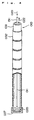
- FIG. 4 is a perspective schematic view of a cell tube portion of the module.
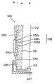
- FIG. 5 is a schematic structural view of a sealing structure at the end of the cell tube.
- a top plate 02, an upper tube sheet 03 and a lower tube sheet 04 are disposed in a module body 01 surrounded by a heat insulator. Below the lower tube sheet 04, a cell chamber 01a is formed. Between the top plate 02 and the upper tube sheet 03 of the module body 01, a fuel supply chamber 05 is formed. Between the upper tube sheet 03 and the lower tube sheet 04, a fuel discharge chamber 06 is formed. To the top plate 02 of the fuel supply chamber 05, an external pipe 07 for establishing communication between the fuel supply chamber 05 and the outside of the module body 01 is connected in such a manner as to pass through the module body 01. Inside of the external pipe 07, an internal pipe 08 passing through the upper tube sheet 03 is disposed for establishing communication between the fuel discharge chamber 06 and the outside of the module body 01.
- Cell tubes 010 each comprising unit cell films (not shown) formed on an outer peripheral surface thereof, passes through, and are supported by, the lower tube sheet 04 such that the upper end of the cell tube 010 is positioned in the fuel discharge chamber 06, and that a lower portion of the cell tube 010 is positioned in the cell chamber 01a of the module body 01.
- a fuel injection pipe 011 passing through the upper tube sheet 03 is disposed for establishing communication between the inner lower portion of the cell tube 010 and the interior of the fuel supply chamber 05.
- a current collecting rod 012 is disposed which has an upper end positioned in the fuel supply chamber 05 and a lower end positioned near the lower end of the cell tube 010.
- the lower end of the current collecting rod 012 is coupled to a current collecting member 013 which is electrically connected to the above-mentioned unit cell films and which closes the lower end of the cell tube 010.
- the upper end of the current collecting rod 012 is electrically connected to the outside of the module body 01 via a current collecting member 013 of nickel and a conductive rod 014.
- a current collecting connector 015 electrically connected to the unit cell films is attached.
- the current collecting connector 015 is series connected to other cell tubes 01 via the same current collecting connectors 015.
- a partition plate 016 of a porous ceramic material is provided in a lower portion of the cell chamber 01a of the module body 01.
- an air preheating chamber 017 communicating with the cell chamber 01a via the partition plate 016 is provided.
- an air supply pipe 018 communicating with the outside of the module body 01 is connected to the air preheating chamber 017.
- an end of an air discharge pipe 019 is located inside the cell chamber 01a of the module body 01.
- the air discharge pipe 019 has the other end located outside the module body 01, and its intermediate portion is disposed in such a manner as to pass through the interior of the air preheating chamber 017 for the purpose of heat exchange.
- a dense conductive connecting material (interconnector) 033 for connecting the fuel electrode and the air electrode.
- a plurality of unit cell films 032 are formed in a lateral-striped pattern. That is, the unit cell film 032 is constituted by the fuel electrode 032a, the solid electrolyte 032b, and the air electrode 032c laminated on the substrate tube 031.
- the interconnectors 033 each seal the interface between the inside and the outside of the substrate tube 031 in the space between the unit cell films 032, thus connecting the unit cell films 032 in series.
- a lead film (Ni-Al) 034 connected via the interconnector 033 to the air electrode 032c located farthest from the substrate tube (15%CaO-ZrO 2 ) 031 is formed on the outer peripheral surface of a lower end portion of the substrate tube 031.
- the lead film 034 is provided with a terminal current collecting member 013, from which current is collected by the current collecting rod 012.
- an airtight film (Al 2 O 3 ) 035 with high airtight properties is formed on the upper surface of the lead film 034.
- a cap-like sealing member 037 is bonded to the airtight film 035 via an inorganic adhesive 036.
- a similar sealing structure is provided for the outer peripheral surface near the upper end, beside the aforementioned tube sheet 04, of the substrate tube 031.
- the airtight film 035 is minimally porous as indicated by its porosity of about 5 to 10%, and thus prevents an escape of gas. Moreover, the airtight film 035 has a great thickness of about 100 to 150 ⁇ m to prevent oxidation of the lead film 034 located underneath.
- the actions of the tubular type solid electrolyte fuel cell module with the foregoing structure will be described.
- the interior of the cell chamber 01a of the module body 01 is heated to an operating temperature (about 900 to 1,000°C).
- a fuel gas 020 such as hydrogen is supplied through the external pipe 07, while air 021 as an oxidant gas is supplied through the air supply pipe 018.
- the fuel gas 020 fed through the external pipe 07 flows from the fuel supply chamber 05 to the lower end of the cell tube 010 via the injection pipe 011.
- the air 021 that has passed through the partition plate 016 via the air preheating chamber 017 flows into the cell chamber 01a.
- the fuel gas 020 permeates through the porous substrate tube 031, and is fed to the fuel electrode 032a of the unit cell film 032.
- the air (oxygen) 021 contacts the air electrode 032c.
- the unit cell film 032 reacts the hydrogen and the air (oxygen) electrochemically to generate power.
- This power is transmitted to the outside via the current collecting member 013, current collecting rod 012, current collecting member 013, and conductive rod 014.
- a residual fuel gas 022 remaining after power generation flows into the fuel discharge chamber 06 from the upper end of the cell tube 010, and is discharged to the outside via the internal pipe 08 for reuse. Residual air 023 remaining after power generation is discharged to the outside via the air discharge pipe 019.
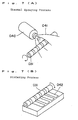
- the above-described cell tube 010 has so far been laborious to produce, because the fuel electrode, electrolyte, and air electrode are sequentially formed as films on the surface of the substrate tube by means of a thermal spray gun 040. Moreover, there has been a raw material loss 041 during film formation owing to the spraying of raw materials from the thermal spray gun 040, and the production cost has been high. Thus, a low cost for mass production has been desired.
- the airtight film 035 obtained by the conventional thermal spraying process comprises coarse particles, and has surface roughness of about 10 to 15 ⁇ m, thus ensuring satisfactory sealability with the adhesive.
- the airtight film obtained by the sintering process has very low surface roughness of about 2 to 5 ⁇ m because of the sintering action. Consequently, adhesion to the adhesive is not satisfactory, and may result in a leak.
- the present invention aims to provide a sealing structure of a sinter type cell tube for a tubular type fuel cell, the sealing structure designed to increase the sealability of the cell tube, thereby enhancing the electrical characteristics of the fuel cell.
- a first aspect of the invention is a sealing structure of a cell tube for a fuel cell, the cell tube comprising a unit cell film prepared by forming a fuel electrode and an air electrode as films on a surface of a substrate tube for the fuel cell by a sintering process, with a solid electrolyte being interposed between the fuel electrode and the air electrode, wherein:
- adhesion to the adhesive can be enhanced to decrease a gas leak.
- formation of the cell tube by the sintering process results in a marked increase in the utilization factor of the raw materials, as compared with the thermal spraying process.
- the production facilities are simpler with the sintering process. Thus, the equipment cost and the production cost can be reduced markedly.
- the sealed portion of the cell tube may be composed of a conductive lead film formed on the surface of the substrate tube, and an airtight film with high airtight properties formed on a surface of the lead film;
- adhesion to the adhesive can be enhanced to decrease a gas leak.
- the adhesion enhancing film may have a rough surface with surface roughness of 10 ⁇ m or more.
- adhesion to the adhesive can be enhanced to decrease a gas leak.
- the adhesion enhancing film may have porosity of 5 to 30%.
- adhesion to the adhesive can be enhanced to decrease a gas leak.
- the adhesion enhancing film may comprise one of, or a mixture of, CaTiO 3 , MgAl 2 O 4 , calcia-stabilized zirconia (CSZ), and yttria-stabilized zirconia (YSZ).
- CSZ calcia-stabilized zirconia
- YSZ yttria-stabilized zirconia
- the adhesion enhancing film may have a film thickness of 20 to 30 ⁇ m.
- adhesion to the adhesive can be enhanced to decrease a gas leak.
- the airtight film may have porosity of 3% or less.
- the gas barrier properties of the film can be improved.
- adhesion to the adhesive can be enhanced to decrease a gas leak.
- the airtight film may have a film thickness of 60 to 100 ⁇ m.
- the gas barrier properties of the film can be improved further.
- adhesion to the adhesive can be enhanced to decrease a gas leak.
- a second aspect of the invention is a tubular type solid electrolyte fuel cell module which supplies an oxidant gas and a fuel gas to a cell tube comprising a unit cell film formed on an outer peripheral surface thereof in a cell chamber in an environment at an operating temperature, to react the oxidant gas and the fuel gas electrochemically, thereby obtaining a power, wherein:
- This module adopts a fuel cell system with markedly increased sealability.
- a third aspect of the invention is a method for producing a cell tube for a fuel cell, comprising:
- the adhesion enhancing film achieving a decrease in the gas leak can be formed.
- a fourth aspect of the invention is a method for producing a cell tube for a fuel cell, comprising:
- a fifth aspect of the invention is a method for producing a cell tube for a fuel cell, comprising:
- the unit cell film and the adhesion enhancing film can be formed simultaneously by sintering performed once. This is efficient.
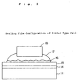
- FIG. 1 is a schematic view showing an example of a sealing structure of a cell tube according to an embodiment of the invention.
- FIG. 2 is a detail view of the sealing structure.
- FIGS. 1 and 2 show a cell tube 13 having unit cell films 12 on a surface of a substrate tube 11 for a fuel cell (hereinafter referred to as "a substrate tube"), each of the unit cell films 12 being constructed by forming a fuel electrode and an air electrode, with a solid electrolyte being interposed between the fuel electrode and the air electrode.
- An adhesion enhancing film having great surface roughness is provided on a sealed portion of the cell tube 13. As shown in FIG.
- the sealed portion of the cell tube is composed of a conductive lead film (e.g., Ni-ZrO 2 ) 14 formed on the surface of the substrate tube (e.g., 15%CaO-ZrO 2 ) 11, and an airtight film (e.g., 8%Y 2 O 3 -ZrO 2 ) 15 with high airtight properties formed on the surface of the lead film 14.
- a conductive lead film e.g., Ni-ZrO 2
- an airtight film e.g., 8%Y 2 O 3 -ZrO 2
- an adhesion enhancing film 16 is provided on the surface of the airtight film 15.
- the surface of the adhesion enhancing film 16 is coated with an inorganic adhesive 17, by which a sealing member 18 is adhered to the adhesion enhancing film 16.
- the adhesion enhancing film 16 preferably has a rough surface with surface roughness of 10 ⁇ m or more. If the surface roughness is less than 10 ⁇ m, the adhesion between the adhesion enhancing film 16 and the adhesive decreases, and may cause a gas leak.
- the upper limit of the surface roughness is not restricted, but is preferably less than 700 ⁇ m as will be shown in Examples to be offered later on.
- the porosity of the adhesion enhancing film 16 is preferably 5 to 30%. If the porosity is less than 5%, the adhesion decreases, and the leak increases. If the porosity exceeds 30%, on the other hand, the strength of the film decreases.
- a material having the following properties (1) to (3) is preferably selected:
- the sealed portion including the tube sheet is exposed to both of an oxidizing atmosphere and a reducing atmosphere as shown in FIG. 1, and thus needs to be prevented from deteriorating.
- the adhesion enhancing film needs to be prevented from reacting with the airtight film underneath and deteriorating.
- a material having the above properties includes, for example, one of CaTiO 3 , MgAl 2 O 4 , calcia-stabilized zirconia (CSZ), and yttria-stabilized zirconia (YSZ), or a mixture of them.
- CSZ calcia-stabilized zirconia
- YSZ yttria-stabilized zirconia
- a material usable in the invention is not restricted to these examples, as long as it has the above-mentioned properties.
- the thickness of the adhesion enhancing film 16 may be such a thickness as will permit satisfactory coating of the adhesive.
- the preferred thickness is 20 to 30 ⁇ m.
- the porosity of the airtight film 15 is set at 3% or less in order to prevent an escape of gas and prevent oxidation of the lead film 14 underneath. Since the porosity of the airtight film 15 is 3% or less, its film thickness can be made 60 to 100 ⁇ m. That is, an airtight film formed by the conventional thermal spraying process has high porosity (5 to 10%), thus requiring a film thickness of about 100 to 150 ⁇ m. On the other hand, an airtight film formed by the sintering process is dense, and thus its film thickness can be decreased to about two-thirds of the film thickness of the conventional airtight film.
- the material for the airtight film 15 may be any material which forms a dense film having low porosity. For example, Al 2 O 3 and yttria-stabilized zirconia (YSZ) can be used.
- the thickness of the airtight film 15 may be 60 to 100 ⁇ m, and the thickness of the adhesion enhancing film 16 may be 20 to 30 ⁇ m.
- the resulting composite film has a total film thickness smaller than the thickness of the airtight film formed by the conventional thermal spraying process.
- the sintering process since the sintering process is employed, there can be provided a sealing structure decreased in production cost and raw materials cost, having satisfactory gas barrier properties, and ensuring high adhesion to the adhesive.
- an air electrode is formed as a film by the sintering process.
- an adhesion enhancing film is formed by the sintering process.
- the sintering temperature of the air electrode at the second stage is higher than the temperature at the first stage.
- a cell tube having the above-described sealing structure is built into a tubular type solid electrolyte fuel cell module as illustrated in FIG. 3. By so doing, a fuel leak is markedly decreased, so that satisfactory power generation by the fuel cell can be performed for a long term.
- the use of the sintering process markedly increases the utilization factor of the raw materials, as compared with the thermal spraying process.
- the sintering process involves simpler production facilities.
- the equipment cost and the production cost can be reduced markedly.
- the fuel cell module using the cell tube produced by the sintering process adopts a fuel cell system with markedly increased sealability.
- composition, porosity, and surface roughness of the adhesion enhancing film of the sealing structure shown in FIG. 2 were set as in Table 1. Under these conditions, the fuel leak (%) was measured.
- the ratio between CaTiO 3 and MgAl 2 O 4 as the materials for the film was set at 1:1, while the porosity and the surface roughness were variously varied as shown in Table 1. Under these conditions, the fuel leak (%) was measured.
- the ratio between CaTiO 3 and MgAl 2 O 4 as the materials for the film was changed to be 3:7 and 7:3. Under these conditions, the fuel leak (%) was measured.
- the ratio between CaTiO 3 and 15mol%CaO-ZrO 2 as the materials for the film was changed to be 2:8 and 3:7. Under these conditions, the fuel leak (%) was measured.
- Table 1 showed that the fuel leak was very small in Examples 1 to 10 using the parameters within the ranges of the present invention.
- the film porosity was 3% and 40% as in Comparative Examples 1 and 2, by contrast, the fuel leak was as great as 20% and 15%, respectively.
- the surface roughness was 5 ⁇ m and 700 ⁇ m, the fuel leak was also as high as 18% and 13%, respectively.
Landscapes
- Life Sciences & Earth Sciences (AREA)
- Engineering & Computer Science (AREA)
- Manufacturing & Machinery (AREA)
- Sustainable Development (AREA)
- Sustainable Energy (AREA)
- Chemical & Material Sciences (AREA)
- Chemical Kinetics & Catalysis (AREA)
- Electrochemistry (AREA)
- General Chemical & Material Sciences (AREA)
- Fuel Cell (AREA)
Abstract
Description

Claims (12)
- A sealing structure of a cell tube for a fuel cell, the cell tube comprising a unit cell film prepared by forming a fuel electrode and an air electrode as films on a surface of a substrate tube for the fuel cell by a sintering process, with a solid electrolyte being interposed between the fuel electrode and the air electrode, wherein:an adhesion enhancing film with great surface roughness is provided on a sealed portion of the cell tube.
- A sealing structure of a cell tube for a fuel cell as claimed in claim 1, wherein:the sealed portion of the cell tube is composed of a conductive lead film formed on the surface of the substrate tube, and an airtight film with high airtight properties formed on a surface of the lead film;the adhesion enhancing film is provided on a surface of the airtight film; anda sealing member is adhered to a surface of the adhesion enhancing film via an adhesive coated on the surface of the adhesion enhancing film.
- A sealing structure of a cell tube for a fuel cell as claimed in claim 1, wherein:the adhesion enhancing film has a rough surface with surface roughness of 10 µm or more.
- A sealing structure of a cell tube for a fuel cell as claimed in claim 1, wherein:the adhesion enhancing film has porosity of 5 to 30%.
- A sealing structure of a cell tube for a fuel cell as claimed in claim 1, wherein:the adhesion enhancing film comprises one of, or a mixture of, CaTiO3, MgAl2O4, calcia-stabilized zirconia (CSZ), and yttria-stabilized zirconia (YSZ).
- A sealing structure of a cell tube for a fuel cell as claimed in claim 1, wherein:the adhesion enhancing film has a film thickness of 20 to 30 µm.
- A sealing structure of a cell tube for a fuel cell as claimed in claim 2, wherein:the airtight film has porosity of 3% or less.
- A sealing structure of a cell tube for a fuel cell as claimed in claim 7, wherein:the airtight film has a film thickness of 60 to 100 µm.
- A tubular type solid electrolyte fuel cell module which supplies an oxidant gas and a fuel gas to a cell tube comprising a unit cell film formed on an outer peripheral surface thereof in a cell chamber in an environment at an operating temperature, to react the oxidant gas and the fuel gas electrochemically, thereby obtaining a power, wherein:a sealing structure of a cell tube for a fuel cell as claimed in any one of claims 1 to 8 is used.
- A method for producing a cell tube for a fuel cell, comprising:forming an adhesion enhancing film by a sintering process simultaneously with forming a fuel electrode and an electrolyte as films on a substrate tube by a sintering process; andthen forming an air electrode as a film by a sintering process.
- A method for producing a cell tube for a fuel cell, comprising:forming a fuel electrode and an electrolyte as films on a substrate tube by a sintering process; andthen forming an adhesion enhancing film by a sintering process simultaneously with forming an air electrode as a film by a sintering process.
- A method for producing a cell tube for a fuel cell, comprising:forming an adhesion enhancing film by a sintering process simultaneously with forming a fuel electrode, an electrolyte, and an air electrode as films on a substrate tube by a sintering process.
Applications Claiming Priority (2)
| Application Number | Priority Date | Filing Date | Title |
|---|---|---|---|
| JP23532999A JP3495654B2 (en) | 1999-08-23 | 1999-08-23 | Cell tube seal structure |
| JP23532999 | 1999-08-23 |
Publications (3)
| Publication Number | Publication Date |
|---|---|
| EP1079453A2 true EP1079453A2 (en) | 2001-02-28 |
| EP1079453A3 EP1079453A3 (en) | 2005-04-06 |
| EP1079453B1 EP1079453B1 (en) | 2007-06-13 |
Family
ID=16984505
Family Applications (1)
| Application Number | Title | Priority Date | Filing Date |
|---|---|---|---|
| EP00117954A Expired - Lifetime EP1079453B1 (en) | 1999-08-23 | 2000-08-21 | Sealing structure of cell tube for a tubular type fuel cell |
Country Status (4)
| Country | Link |
|---|---|
| US (1) | US6562505B1 (en) |
| EP (1) | EP1079453B1 (en) |
| JP (1) | JP3495654B2 (en) |
| DE (1) | DE60035152T2 (en) |
Cited By (2)
| Publication number | Priority date | Publication date | Assignee | Title |
|---|---|---|---|---|
| WO2013020997A1 (en) | 2011-08-09 | 2013-02-14 | Robert Bosch Gmbh | Fuel cell, fuel cell assembly, and method for producing a fuel cell |
| GB2497843A (en) * | 2011-11-30 | 2013-06-26 | Bosch Gmbh Robert | Fixing of fuel cell to a support |
Families Citing this family (18)
| Publication number | Priority date | Publication date | Assignee | Title |
|---|---|---|---|---|
| JP4562951B2 (en) * | 2001-06-01 | 2010-10-13 | 三菱重工業株式会社 | SUBSTRATE TUBE FOR FUEL CELL, SUBSTRATE TUBE MATERIAL FOR FUEL CELL, AND METHOD FOR PRODUCING FUEL CELL CELL |
| JP2003045455A (en) * | 2001-07-26 | 2003-02-14 | Hitachi Ltd | High temperature solid oxide fuel cell |
| JP5001495B2 (en) * | 2001-09-27 | 2012-08-15 | 三菱重工業株式会社 | Fuel cell system and fuel cell operating method |
| JP4790439B2 (en) * | 2006-02-09 | 2011-10-12 | 富士通株式会社 | Electrodes, electronic components and substrates |
| JP5173458B2 (en) * | 2008-01-31 | 2013-04-03 | 三菱重工業株式会社 | Fuel cell cell tube seal structure and fuel cell module |
| JP5311931B2 (en) * | 2008-08-28 | 2013-10-09 | 京セラ株式会社 | Fuel cell stack and fuel cell module using the same |
| JP5461238B2 (en) * | 2010-02-26 | 2014-04-02 | 三菱重工業株式会社 | Solid oxide fuel cell |
| JP5449120B2 (en) * | 2010-12-17 | 2014-03-19 | 三菱重工業株式会社 | Method for forming seal component and method for manufacturing solid oxide fuel cell module |
| DE102011081540A1 (en) * | 2011-08-25 | 2013-02-28 | Robert Bosch Gmbh | Fuel cell for production of energy, has functional body i.e. one-sided closed tube, including two electrical interconnected segment strands aligned in axial direction with respect to axis of functional body |
| JP5931420B2 (en) * | 2011-11-30 | 2016-06-08 | 三菱日立パワーシステムズ株式会社 | Solid oxide fuel cell, solid oxide fuel cell cartridge, solid oxide fuel cell module, and method for producing solid oxide fuel cell |
| DE102012221449A1 (en) | 2011-11-30 | 2013-06-06 | Robert Bosch Gmbh | High temperature fuel cell system for e.g. combined heat and power plant, has source mat arranged between base portion of fuel cell e.g. high temperature fuel cell, and edge sections of carrier element |
| DE102012219104A1 (en) | 2012-10-19 | 2014-05-08 | Robert Bosch Gmbh | Electrochemical cell with tubular carrier grid |
| DE102013212417A1 (en) | 2013-06-27 | 2014-12-31 | Robert Bosch Gmbh | MIM High-temperature cells connection |
| JP6072104B2 (en) * | 2015-02-06 | 2017-02-01 | 三菱重工業株式会社 | Cell stack A fuel cell module having this and a cell stack manufacturing method |
| JP6608084B1 (en) * | 2018-12-27 | 2019-11-20 | 日本碍子株式会社 | Electrochemical cell stack |
| JP6608085B1 (en) * | 2018-12-27 | 2019-11-20 | 日本碍子株式会社 | Electrochemical cell stack |
| JP6633236B1 (en) | 2019-02-26 | 2020-01-22 | 三菱日立パワーシステムズ株式会社 | Fuel cell, fuel cell module, power generation system, high-temperature steam electrolysis cell, and methods for producing them |
| JP7064077B1 (en) * | 2021-02-22 | 2022-05-10 | 三菱重工業株式会社 | A method for manufacturing a sealing material for an electrochemical reaction cell, an electrochemical reaction cell cartridge, and a sealing material for an electrochemical reaction cell. |
Family Cites Families (6)
| Publication number | Priority date | Publication date | Assignee | Title |
|---|---|---|---|---|
| JPH0414766A (en) * | 1990-05-07 | 1992-01-20 | Mitsubishi Heavy Ind Ltd | Solid electrolyte fuel cell |
| US5342703A (en) * | 1991-07-19 | 1994-08-30 | Ngk Insulators, Ltd. | Solid electrolyte type fuel cell and method for producing the same |
| JPH05234607A (en) * | 1992-02-20 | 1993-09-10 | Murata Mfg Co Ltd | Solid electrolyte type fuel cell |
| JPH0633282A (en) * | 1992-07-15 | 1994-02-08 | Mitsubishi Heavy Ind Ltd | Solid electrolyte electrolysis cell |
| US5336570A (en) * | 1992-08-21 | 1994-08-09 | Dodge Jr Cleveland E | Hydrogen powered electricity generating planar member |
| JPH08185882A (en) * | 1994-12-28 | 1996-07-16 | Mitsubishi Heavy Ind Ltd | Method for manufacturing solid oxide fuel cell |
-
1999
- 1999-08-23 JP JP23532999A patent/JP3495654B2/en not_active Expired - Lifetime
-
2000
- 2000-08-15 US US09/637,704 patent/US6562505B1/en not_active Expired - Lifetime
- 2000-08-21 EP EP00117954A patent/EP1079453B1/en not_active Expired - Lifetime
- 2000-08-21 DE DE60035152T patent/DE60035152T2/en not_active Expired - Lifetime
Cited By (3)
| Publication number | Priority date | Publication date | Assignee | Title |
|---|---|---|---|---|
| WO2013020997A1 (en) | 2011-08-09 | 2013-02-14 | Robert Bosch Gmbh | Fuel cell, fuel cell assembly, and method for producing a fuel cell |
| GB2497843A (en) * | 2011-11-30 | 2013-06-26 | Bosch Gmbh Robert | Fixing of fuel cell to a support |
| GB2497843B (en) * | 2011-11-30 | 2018-05-09 | Bosch Gmbh Robert | Fuel cell system |
Also Published As
| Publication number | Publication date |
|---|---|
| EP1079453B1 (en) | 2007-06-13 |
| DE60035152T2 (en) | 2007-10-11 |
| DE60035152D1 (en) | 2007-07-26 |
| JP2001060462A (en) | 2001-03-06 |
| JP3495654B2 (en) | 2004-02-09 |
| US6562505B1 (en) | 2003-05-13 |
| EP1079453A3 (en) | 2005-04-06 |
Similar Documents
| Publication | Publication Date | Title |
|---|---|---|
| EP1079453B1 (en) | Sealing structure of cell tube for a tubular type fuel cell | |
| US7118777B2 (en) | Structures and fabrication techniques for solid state electrochemical devices | |
| US7901837B2 (en) | Structures for dense, crack free thin films | |
| CN102067370B (en) | Integrated seal for high-temperature electrochemical device | |
| EP0497542B1 (en) | Method for producing lanthanum chromite film and method for producing interconnector for solid electrolyte type fuel cells | |
| US6921557B2 (en) | Process for making dense thin films | |
| EP0552055B1 (en) | A process for producing solid oxide fuel cells | |
| CN1653638A (en) | Electrochemical cell stack assembly | |
| JP2008525967A (en) | High specific power solid oxide fuel cell stack | |
| US20070072070A1 (en) | Substrates for deposited electrochemical cell structures and methods of making the same | |
| JP2011519114A (en) | Ceramic interconnects for fuel cell stacks | |
| US6534211B1 (en) | Fuel cell having an air electrode with decreased shrinkage and increased conductivity | |
| US8211587B2 (en) | Plasma sprayed ceramic-metal fuel electrode | |
| JPH08236138A (en) | Solid oxide fuel cell and method for manufacturing the same | |
| JP3339998B2 (en) | Cylindrical fuel cell | |
| Tucker et al. | Metal Supported SOFCs | |
| JPH05174846A (en) | Solid oxide fuel cell | |
| JP4721487B2 (en) | Solid electrolyte fuel cell and fuel cell | |
| JPH0574468A (en) | Solid electrolyte fuel cell | |
| JPH0869803A (en) | Solid oxide fuel cell and method for manufacturing the same |
Legal Events
| Date | Code | Title | Description |
|---|---|---|---|
| PUAI | Public reference made under article 153(3) epc to a published international application that has entered the european phase |
Free format text: ORIGINAL CODE: 0009012 |
|
| 17P | Request for examination filed |
Effective date: 20000913 |
|
| AK | Designated contracting states |
Kind code of ref document: A2 Designated state(s): AT BE CH CY DE DK ES FI FR GB GR IE IT LI LU MC NL PT SE |
|
| AX | Request for extension of the european patent |
Free format text: AL;LT;LV;MK;RO;SI |
|
| PUAL | Search report despatched |
Free format text: ORIGINAL CODE: 0009013 |
|
| AK | Designated contracting states |
Kind code of ref document: A3 Designated state(s): AT BE CH CY DE DK ES FI FR GB GR IE IT LI LU MC NL PT SE |
|
| AX | Request for extension of the european patent |
Extension state: AL LT LV MK RO SI |
|
| AKX | Designation fees paid |
Designated state(s): DE NL |
|
| GRAP | Despatch of communication of intention to grant a patent |
Free format text: ORIGINAL CODE: EPIDOSNIGR1 |
|
| GRAS | Grant fee paid |
Free format text: ORIGINAL CODE: EPIDOSNIGR3 |
|
| GRAA | (expected) grant |
Free format text: ORIGINAL CODE: 0009210 |
|
| AK | Designated contracting states |
Kind code of ref document: B1 Designated state(s): DE NL |
|
| REF | Corresponds to: |
Ref document number: 60035152 Country of ref document: DE Date of ref document: 20070726 Kind code of ref document: P |
|
| NLV1 | Nl: lapsed or annulled due to failure to fulfill the requirements of art. 29p and 29m of the patents act | ||
| PG25 | Lapsed in a contracting state [announced via postgrant information from national office to epo] |
Ref country code: NL Free format text: LAPSE BECAUSE OF FAILURE TO SUBMIT A TRANSLATION OF THE DESCRIPTION OR TO PAY THE FEE WITHIN THE PRESCRIBED TIME-LIMIT Effective date: 20070613 |
|
| PLBE | No opposition filed within time limit |
Free format text: ORIGINAL CODE: 0009261 |
|
| STAA | Information on the status of an ep patent application or granted ep patent |
Free format text: STATUS: NO OPPOSITION FILED WITHIN TIME LIMIT |
|
| 26N | No opposition filed |
Effective date: 20080314 |
|
| REG | Reference to a national code |
Ref country code: DE Ref legal event code: R082 Ref document number: 60035152 Country of ref document: DE Representative=s name: ADVOTEC. PATENT- UND RECHTSANWAELTE, DE Ref country code: DE Ref legal event code: R081 Ref document number: 60035152 Country of ref document: DE Owner name: MITSUBISHI HITACHI POWER SYSTEMS, LTD., YOKOHA, JP Free format text: FORMER OWNER: MITSUBISHI HEAVY INDUSTRIES, LTD., TOKYO, JP |
|
| PGFP | Annual fee paid to national office [announced via postgrant information from national office to epo] |
Ref country code: DE Payment date: 20190806 Year of fee payment: 20 |
|
| REG | Reference to a national code |
Ref country code: DE Ref legal event code: R071 Ref document number: 60035152 Country of ref document: DE |