EP1079408A2 - Supplemental trip unit for rotary circuit interrupters - Google Patents
Supplemental trip unit for rotary circuit interrupters Download PDFInfo
- Publication number
- EP1079408A2 EP1079408A2 EP00307196A EP00307196A EP1079408A2 EP 1079408 A2 EP1079408 A2 EP 1079408A2 EP 00307196 A EP00307196 A EP 00307196A EP 00307196 A EP00307196 A EP 00307196A EP 1079408 A2 EP1079408 A2 EP 1079408A2
- Authority
- EP
- European Patent Office
- Prior art keywords
- circuit breaker
- trip
- operating mechanism
- arm
- trip unit
- Prior art date
- Legal status (The legal status is an assumption and is not a legal conclusion. Google has not performed a legal analysis and makes no representation as to the accuracy of the status listed.)
- Granted
Links
Images


Classifications
-
- H—ELECTRICITY
- H01—ELECTRIC ELEMENTS
- H01H—ELECTRIC SWITCHES; RELAYS; SELECTORS; EMERGENCY PROTECTIVE DEVICES
- H01H71/00—Details of the protective switches or relays covered by groups H01H73/00 - H01H83/00
- H01H71/10—Operating or release mechanisms
- H01H71/12—Automatic release mechanisms with or without manual release
- H01H71/24—Electromagnetic mechanisms
- H01H71/2472—Electromagnetic mechanisms with rotatable armatures
-
- H—ELECTRICITY
- H01—ELECTRIC ELEMENTS
- H01H—ELECTRIC SWITCHES; RELAYS; SELECTORS; EMERGENCY PROTECTIVE DEVICES
- H01H1/00—Contacts
- H01H1/12—Contacts characterised by the manner in which co-operating contacts engage
- H01H1/14—Contacts characterised by the manner in which co-operating contacts engage by abutting
- H01H1/20—Bridging contacts
- H01H1/2041—Rotating bridge
- H01H1/2058—Rotating bridge being assembled in a cassette, which can be placed as a complete unit into a circuit breaker
-
- H—ELECTRICITY
- H01—ELECTRIC ELEMENTS
- H01H—ELECTRIC SWITCHES; RELAYS; SELECTORS; EMERGENCY PROTECTIVE DEVICES
- H01H71/00—Details of the protective switches or relays covered by groups H01H73/00 - H01H83/00
- H01H71/10—Operating or release mechanisms
- H01H71/12—Automatic release mechanisms with or without manual release
- H01H71/123—Automatic release mechanisms with or without manual release using a solid-state trip unit
- H01H2071/124—Automatic release mechanisms with or without manual release using a solid-state trip unit with a hybrid structure, the solid state trip device being combined with a thermal or a electromagnetic trip
-
- H—ELECTRICITY
- H01—ELECTRIC ELEMENTS
- H01H—ELECTRIC SWITCHES; RELAYS; SELECTORS; EMERGENCY PROTECTIVE DEVICES
- H01H71/00—Details of the protective switches or relays covered by groups H01H73/00 - H01H83/00
- H01H71/10—Operating or release mechanisms
- H01H71/12—Automatic release mechanisms with or without manual release
- H01H71/24—Electromagnetic mechanisms
- H01H71/2454—Electromagnetic mechanisms characterised by the magnetic circuit or active magnetic elements
Definitions
- This invention relates to rotary circuit breakers, and, more particularly to a Supplemental Trip Unit for Rotary Circuit Interrupters.
- a supplemental magnetic trip units is arranged on the load strap of an industrial-rated circuit breaker to interrupt circuit current upon occurrence of a short circuit fault.
- the trip unit employs a U-shaped magnet and a hinged armature that articulates the circuit breaker operating mechanism latch to allow the circuit breaker contacts to become separated upon the emergence of the powerful circuit breaker operating mechanism springs.
- a return spring mounted between the trip slide and the circuit breaker operating mechanism sideframe allows the armature to return automatically to a home position.
- thermo magnetic trip unit As described, for example in U.S Patent No. 3,464,040 entitled Compact Circuit Breaker Construction.
- a bimetal element is connected with the associated electric circuit for long term overcurrent detection and interrupting the circuit when the overcurrent persists for a predetermined period of time. The time for the heat to become dissipated from the bimetal provides the time factor in the predetermined current/time value.
- a magnetic element in the form of a U-shaped magnet is employed for short time overcurrent detection and interrupting the circuit when the overcurrent persists for a shorter predetermined period of time.
- the magnet partially surrounds the current-carrying bimetal and electromagnetically interacts with a pivotal armature member to interrupt circuit current within a shorter period of time based on the exponential increase in magnetic attraction between the magnet and the armature as the armature begins to move toward the magnet.
- the electronic trip unit providing the long time and short time overcurrent determination from data stored within electronic memory.
- a circuit breaker rotary contact assembly is generally shown at 10 and is similar to that described within the U.S. Patent Application Serial No. (Docket No. 41PR7613/7619) entitled Rotary Contact Assembly for High-Ampere Rated Circuit Breakers, filed concurrently herewith.
- Opposing line and load straps 11, 12 are adapted for connection with an associated electrical distribution system and a protected electric circuit, respectively.
- Fixed contacts 24, 26 connect with the line and load straps while the moveable contacts 23, 25 are attached to ends of moveable contact arms 21, 22 for making movable connection with the associated fixed contacts to complete the circuit connection with the line and load straps 11, 12.
- the movable contact arms 21, 22 are of unitary structure and rotate within a rotor and contact arm assembly 15 about a contact arm pivot 27 when rotated upon response to the circuit breaker operating mechanism (not shown) by connection via pins 18 and a pair of opposing levers 16, 17.
- the arcs generated when contacts 23, 24 and 25, 26 are separated upon overload circuit current conditions are cooled and quenched within arc chambers 13, 14 to interrupt current through the protected circuit.
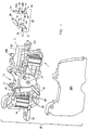
- a supplemental magnetic trip unit 28 is attached to the load end of the circuit breaker 10 by positioning a U-shaped magnet 29 on a top part 11B of the load strap 11 with a sidearm 31 containing an armature slot 32 extending about a sidearm 33.
- Plastic cassette sidepieces 36A, 36B insulate the supplemental magnetic trip unit 28 shown within the sidepieces 36A and B, with sidepiece 36A shown unattached.
- An armature 30 is positioned onto the magnet by insertion of a pivot arm 34, shaped on one end of the armature within the armature slot such that an actuator arm 35, shaped on the opposite end of the armature, extends above the sidearm 33.
- a trip slide unit 40 in the form of a shaped plate 43, containing slotted openings 42A and B is positioned next to the magnet/armature assembly 29, 30 by locating a bouoin arm 44 containing a retainer pin 48 under the magnet/armature assembly and arranging a top arm 45 under the actuator arm 35.
- a trip tab 41 extending from the top of a shaped plate 43 becomes positioned above a circuit breaker operating assembly latch 39, on an operating mechanism sideframe 38, as best seen by now referring to Figure 2.
- the circuit breaker operating mechanism contained within the operating mechanism sideframe 38, shown in Figure 2 is described on U.S. Patent No. 5,797,483 entitled Operating Mechanism Linkage Assembly for High Ampere-Rated Circuit Breakers.
- the magnet/armature assembly 29,30 of the supplemental magnetic trip unit 28 is shown arranged around the on the top part 11B of the load strap 11 ( Figure 1) within the cassette 36A and B and with the armature actuator arm 35 over the top arm 45 of the trip slide assembly 40.
- the supplemental magnetic trip unit 28 is now shown within the rotary contact assembly 10 at the load end of the circuit breaker operating mechanism sideframe 38 of Figure 3 containing the circuit breaker operating mechanism described within the above-mentioned U.S. Patent No. 5,797,483.
- the circuit breaker operating handle 9 is shown extending through the operating handle slot 8 formed within the operating handle cover 7 extending over the supplemental magnetic trip unit 28.
- the magnet/armature assembly 29, 30 surrounds the top part 11B of the load strap 11 with the bottom part 11A arranged for connection with an electric distribution circuit.
- the actuator arm 35 is superjacent a top arm 45 of the trip slide unit 40, with a return spring 49 extending between pin 48 on the bottom arm 44 of the shaped plate 43 and a pin 50 on the operating mechanism sideframe 38.
- Additional operating mechanism sideframe pins 46, 47 serve to guide translation of the shaped plate 43 by means of the elongated slots 42A and B.
- An auxiliary magnetic trip unit has herein been described in the form of a simple magnet and armature arranged around the circuit breaker load strap for articulation of the circuit breaker operating mechanism independent of the circuit breaker electronic trip unit by interaction of a trip slide upon occurrence of a short circuit overcurrent condition.
Landscapes
- Physics & Mathematics (AREA)
- Electromagnetism (AREA)
- Breakers (AREA)
Abstract
Description
Claims (9)
- A magnetic trip unit for a circuit breaker load strap comprising:a U-shaped magnet (29) having a pair of first and second upstanding sidearms (31, 33), one of said first sidearms having a magnet slot (32) at one end thereof;an armature (30) having a pivot arm (34) at one end thereof and an actuator arm (35) at an opposite end thereof, said pivot arm being partially captured within said magnet slot (32); anda trip slide plate (43) having a trip tab (41) at a top thereof and a pair of first and second arms (44, 45) extending from one side, said first arm (44) being positioned under said armature (30) and said second arm (45) being positioned under said actuator arm (35), whereby said armature (30) and said actuator arm (35) become attracted to said second arm (45) when said magnet (24) and said armature (30) encompass a part of said load strap (11) upon transfer of current of a predetermined value through said load strap (11).
- The magnetic trip unit of claim 1 further including:a pair of first and second elongated slots (42A, 42B) formed through said trip slide plate (43), said first slot (42A) being arranged above said second slot (42B) for capturing first and second pins (46, 47) on a circuit breaker operating mechanism sideframe (38).
- The magnetic trip unit of claim 2 further including:a trip slide plate spring retainer pin (48) on said trip plate second arm (44).
- The magnetic trip unit of claim 1 wherein said trip tab (41) interacts with a circuit breaker operating mechanism latch (39) for articulating a circuit breaker operating mechanism upon transfer of current of a predetermined value through said load strap (11).
- The magnetic trip unit of claim 4 including:a return spring (49) connecting between said trip slide plate spring retainer pin (48) and a circuit breaker operating mechanism trip retainer pin (50) for returning said trip slide plate (43) to a home position after completion of articulation of a circuit breaker operating mechanism.
- The magnetic trip unit of claim 5 including:a non-metallic cassette, whereby said armature (30), magnet (29) and trip slide plate (43) are arranged within said cassette.
- The magnetic trip unit of claim 6 including:arc gas release slots formed on said cassette.
- The circuit breaker of claim 5 where:said trip slide plate (43) is moveably-attached to said operating mechanism sideplate (38).
- A circuit breaker having first and second pairs of separable contacts (23,24,25,26) arranged on opposite ends of a circuit breaker contact arm (21) within a circuit breaker operating mechanism sideframe (38), a load strap (11) connecting with said contacts (24,26) which are separated upon occurrence of predetermined overcurrent conditions through said contacts, said circuit breaker comprising a magnetic trip unit for the load strap in accordance with any one of claims 1 to 8.
Applications Claiming Priority (2)
| Application Number | Priority Date | Filing Date | Title |
|---|---|---|---|
| US09/384,495 US6175288B1 (en) | 1999-08-27 | 1999-08-27 | Supplemental trip unit for rotary circuit interrupters |
| US384495 | 1999-08-27 |
Publications (3)
| Publication Number | Publication Date |
|---|---|
| EP1079408A2 true EP1079408A2 (en) | 2001-02-28 |
| EP1079408A3 EP1079408A3 (en) | 2003-03-26 |
| EP1079408B1 EP1079408B1 (en) | 2007-01-03 |
Family
ID=23517527
Family Applications (1)
| Application Number | Title | Priority Date | Filing Date |
|---|---|---|---|
| EP00307196A Expired - Lifetime EP1079408B1 (en) | 1999-08-27 | 2000-08-22 | Supplemental trip unit for rotary circuit interrupters |
Country Status (4)
| Country | Link |
|---|---|
| US (1) | US6175288B1 (en) |
| EP (1) | EP1079408B1 (en) |
| DE (1) | DE60032683T2 (en) |
| PL (1) | PL196612B1 (en) |
Cited By (2)
| Publication number | Priority date | Publication date | Assignee | Title |
|---|---|---|---|---|
| CN100466137C (en) * | 2006-10-13 | 2009-03-04 | Tcl低压电器(无锡)有限公司 | Electromagnetic residual current action protector and its protecting method |
| WO2023205007A1 (en) * | 2022-04-20 | 2023-10-26 | Sensata Technologies Inc. | Electromechanical rotary latch for use in current interruption devices |
Families Citing this family (18)
| Publication number | Priority date | Publication date | Assignee | Title |
|---|---|---|---|---|
| US6629044B1 (en) | 2000-03-17 | 2003-09-30 | General Electric Company | Electrical distribution analysis method and apparatus |
| US6882258B2 (en) | 2001-02-27 | 2005-04-19 | General Electric Company | Mechanical bell alarm assembly for a circuit breaker |
| US6903635B2 (en) * | 2003-05-13 | 2005-06-07 | General Electric Company | Circuit breaker interface mechanism for auxiliary switch accessory |
| US6778048B1 (en) | 2003-05-13 | 2004-08-17 | General Electric Company | Circuit breaker interface mechanism for bell alarm switch |
| US6985059B2 (en) * | 2003-09-10 | 2006-01-10 | General Electric Company | Circuit breaker handle block |
| US6930577B2 (en) * | 2003-09-15 | 2005-08-16 | General Electric Company | Circuit breaker lug cover and gasket |
| US8093965B2 (en) * | 2008-12-03 | 2012-01-10 | Schneider Electric USA, Inc. | Add-on trip module for multi-pole circuit breaker |
| US8093964B2 (en) * | 2008-12-29 | 2012-01-10 | Schneider Electric USA, Inc. | Add-on trip module for multi-pole circuit breaker |
| US8350168B2 (en) | 2010-06-30 | 2013-01-08 | Schneider Electric USA, Inc. | Quad break modular circuit breaker interrupter |
| EP2826050B1 (en) * | 2012-03-12 | 2017-04-26 | Siemens Aktiengesellschaft | Circuit breaker trip blocking apparatus, systems and methods of operation |
| FR3007573B1 (en) | 2013-06-20 | 2015-07-17 | Schneider Electric Ind Sas | TRIGGER AND METHOD FOR MANUFACTURING SUCH TRIGGER |
| US9324528B1 (en) * | 2014-11-17 | 2016-04-26 | General Electric Company | Magnetic trip mechanism for circuit breaker |
| DE102017100251B4 (en) | 2017-01-09 | 2023-12-14 | Hanon Systems | Arrangement with a device for receiving and supporting busbars |
| CN106653508B (en) * | 2017-01-19 | 2018-08-21 | 上海电器股份有限公司人民电器厂 | Electromagnetic short current protective device for breaker |
| JP7035879B2 (en) * | 2018-07-24 | 2022-03-15 | 株式会社Soken | Contact devices and electromagnetic relays |
| US11289294B2 (en) * | 2019-07-10 | 2022-03-29 | Eaton Intelligent Power Limited | Rotary switch and circuit interrupter including the same |
| US11764022B2 (en) * | 2021-04-27 | 2023-09-19 | Carling Technologies, Inc. | Slim circuit breaker |
| CN120690643A (en) * | 2024-03-22 | 2025-09-23 | 施耐德电气工业公司 | A circuit breaker |
Family Cites Families (213)
| Publication number | Priority date | Publication date | Assignee | Title |
|---|---|---|---|---|
| US2340682A (en) | 1942-05-06 | 1944-02-01 | Gen Electric | Electric contact element |
| US2719203A (en) | 1952-05-02 | 1955-09-27 | Westinghouse Electric Corp | Circuit breakers |
| US2937254A (en) | 1957-02-05 | 1960-05-17 | Gen Electric | Panelboard unit |
| US3162739A (en) | 1962-06-25 | 1964-12-22 | Gen Electric | Electric circuit breaker with improved trip means |
| US3158717A (en) | 1962-07-18 | 1964-11-24 | Gen Electric | Electric circuit breaker including stop means for limiting movement of a toggle linkage |
| US3197582A (en) | 1962-07-30 | 1965-07-27 | Fed Pacific Electric Co | Enclosed circuit interrupter |
| US3201539A (en) * | 1963-01-23 | 1965-08-17 | Ite Circuit Breaker Ltd | Single turn trip coil having novel core and armature configurations |
| DE1227978B (en) | 1963-10-04 | 1966-11-03 | Licentia Gmbh | Electrical switchgear, in particular contactor |
| US3307002A (en) | 1965-02-04 | 1967-02-28 | Texas Instruments Inc | Multipole circuit breaker |
| FR1585120A (en) | 1967-07-24 | 1970-01-09 | ||
| US3464040A (en) | 1967-09-21 | 1969-08-26 | Gen Electric | Compact circuit breaker construction |
| CH481479A (en) * | 1967-10-11 | 1969-11-15 | Maier & Cie C | Magnetic release for circuit breaker |
| US3548358A (en) * | 1969-05-19 | 1970-12-15 | Gen Electric | Electric circuit breaker with bimetallic strip protective means |
| US3631369A (en) | 1970-04-27 | 1971-12-28 | Ite Imperial Corp | Blowoff means for circuit breaker latch |
| US3803455A (en) | 1973-01-02 | 1974-04-09 | Gen Electric | Electric circuit breaker static trip unit with thermal override |
| FR2241868B1 (en) | 1973-08-20 | 1976-06-18 | Merlin Gerin | |
| US3883781A (en) | 1973-09-06 | 1975-05-13 | Westinghouse Electric Corp | Remote controlled circuit interrupter |
| FR2360171A1 (en) | 1976-07-30 | 1978-02-24 | Unelec | CIRCUIT BREAKER CONTROL MECHANISM |
| FR2361737A1 (en) | 1976-08-09 | 1978-03-10 | Unelec | CIRCUIT BREAKER WITH LOCKING DEVICE FOR THE CONTROL HANDLE IN THE EVENT OF WELDING OF THE CONTACTS |
| US4158119A (en) | 1977-07-20 | 1979-06-12 | Gould Inc. | Means for breaking welds formed between circuit breaker contacts |
| US4144513A (en) | 1977-08-18 | 1979-03-13 | Gould Inc. | Anti-rebound latch for current limiting switches |
| FR2410353A1 (en) | 1977-11-28 | 1979-06-22 | Merlin Gerin | Polarised relay for differential circuit breaker - has magnetic yoke having two L=shaped legs, one carrying de-energising coil and other completing loop with permanent magnet |
| US4166988A (en) | 1978-04-19 | 1979-09-04 | General Electric Company | Compact three-pole circuit breaker |
| FR2429487A1 (en) | 1978-06-23 | 1980-01-18 | Merlin Gerin | CIRCUIT BREAKER WITH REMOVABLE TRIGGER BLOCK |
| US4259651A (en) | 1978-10-16 | 1981-03-31 | Westinghouse Electric Corp. | Current limiting circuit interrupter with improved operating mechanism |
| US4220934A (en) | 1978-10-16 | 1980-09-02 | Westinghouse Electric Corp. | Current limiting circuit breaker with integral magnetic drive device housing and contact arm stop |
| FR2452175A1 (en) | 1979-03-23 | 1980-10-17 | Alsthom Unelec Sa | ELECTRICAL AIR CUT-OFF APPARATUS PROVIDED WITH A SHORT-CIRCUIT INDICATOR DEVICE |
| US4263492A (en) | 1979-09-21 | 1981-04-21 | Westinghouse Electric Corp. | Circuit breaker with anti-bounce mechanism |
| US4297663A (en) | 1979-10-26 | 1981-10-27 | General Electric Company | Circuit breaker accessories packaged in a standardized molded case |
| FR2478368A1 (en) | 1980-03-12 | 1981-09-18 | Merlin Gerin | MANEUVER MECHANISM FOR TETRAPOLAR CIRCUIT BREAKER |
| JPS613106Y2 (en) | 1980-04-10 | 1986-01-31 | ||
| US4301342A (en) | 1980-06-23 | 1981-11-17 | General Electric Company | Circuit breaker condition indicator apparatus |
| DE3033213C2 (en) | 1980-08-29 | 1982-10-21 | Siemens AG, 1000 Berlin und 8000 München | Low voltage circuit breaker with a locking lever |
| DE8023509U1 (en) | 1980-08-29 | 1980-11-27 | Siemens Ag, 1000 Berlin Und 8000 Muenchen | Low voltage circuit breaker for locking lever |
| DE3034790A1 (en) | 1980-09-15 | 1982-03-25 | Siemens AG, 1000 Berlin und 8000 München | CIRCUIT BREAKER |
| US4541032A (en) | 1980-10-21 | 1985-09-10 | B/K Patent Development Company, Inc. | Modular electrical shunts for integrated circuit applications |
| JPS57102281U (en) | 1980-12-16 | 1982-06-23 | ||
| DE3047360C2 (en) | 1980-12-16 | 1987-08-20 | Karl Pfisterer Elektrotechnische Spezialartikel Gmbh & Co Kg, 7000 Stuttgart | Switching strip |
| DE3110960A1 (en) | 1981-03-20 | 1982-09-30 | Basf Ag, 6700 Ludwigshafen | ELECTROPHOTOGRAPHIC RECORDING MATERIAL |
| US4360852A (en) | 1981-04-01 | 1982-11-23 | Allis-Chalmers Corporation | Overcurrent and overtemperature protective circuit for power transistor system |
| FR2505553A1 (en) | 1981-05-07 | 1982-11-12 | Merlin Gerin | MULTIPOLAR CIRCUIT BREAKER WITH INTERCHANGEABLE MAGNETOTHERMIC TRIGGER |
| FR2506066A1 (en) | 1981-05-18 | 1982-11-19 | Merlin Gerin | MANEUVERING MECHANISM OF A LOW VOLTAGE MULTIPOLAR ELECTRIC CIRCUIT BREAKER |
| FR2512582A1 (en) | 1981-09-10 | 1983-03-11 | Merlin Gerin | Tamperproof differential relay - uses screw-in cover to clip together two modules of earth leakage relay |
| FR2514195A1 (en) | 1981-10-05 | 1983-04-08 | Merlin Gerin | MULTIPOLAR CIRCUIT BREAKER WITH REMOVABLE TRIGGER BLOCK |
| FR2516305A1 (en) * | 1981-11-06 | 1983-05-13 | Merlin Gerin | CONNECTION BREAKER WITH POWER CONTROL SUBSCRIBED BY A PILOT MODULE |
| US4658322A (en) | 1982-04-29 | 1987-04-14 | The United States Of America As Represented By The Secretary Of The Navy | Arcing fault detector |
| US4470027A (en) | 1982-07-16 | 1984-09-04 | Eaton Corporation | Molded case circuit breaker with improved high fault current interruption capability |
| IT8223118V0 (en) | 1982-10-07 | 1982-10-07 | Sace Spa | ELECTRIC SWITCH WITH STOPPING THE CONTROL LEVER STROKE IN CASE OF WELDING THE CONTACTS. |
| US4492941A (en) | 1983-02-18 | 1985-01-08 | Heinemann Electric Company | Circuit breaker comprising parallel connected sections |
| US4488133A (en) | 1983-03-28 | 1984-12-11 | Siemens-Allis, Inc. | Contact assembly including spring loaded cam follower overcenter means |
| FR2547122B1 (en) | 1983-06-03 | 1985-07-05 | Merlin Gerin | SELECTIVE ELECTRONIC TRIGGER ASSOCIATED WITH A LIMITING CIRCUIT BREAKER |
| JPS6068524A (en) | 1983-09-21 | 1985-04-19 | 三菱電機株式会社 | Circuit breaker |
| FR2553929B1 (en) | 1983-10-21 | 1986-08-01 | Merlin Gerin | CONTROL MECHANISM OF A LOW VOLTAGE MULTIPOLAR CIRCUIT BREAKER |
| FR2553943B1 (en) | 1983-10-24 | 1986-04-11 | Merlin Gerin | RESIDUAL DIFFERENTIAL DEVICE PROVIDED WITH A DEVICE FOR MONITORING THE ELECTRONIC POWER SOURCE |
| DE3347120A1 (en) | 1983-12-22 | 1985-07-11 | Siemens AG, 1000 Berlin und 8000 München | ELECTRO-DYNAMIC OPENING CONTACT SYSTEM |
| IT1173269B (en) | 1984-02-15 | 1987-06-18 | Cge Comp Gen Elettromecc | COMBINATION OF COUPLING CONNECTION AND RELEASE DEVICE TO AVOID THE CLOSING OF THE CONTACTS OF AN AUTOMATIC SWITCH AFTER AN OPENING DUE TO SHORT CIRCUIT |
| US4550360A (en) | 1984-05-21 | 1985-10-29 | General Electric Company | Circuit breaker static trip unit having automatic circuit trimming |
| US4672501A (en) | 1984-06-29 | 1987-06-09 | General Electric Company | Circuit breaker and protective relay unit |
| IT1175633B (en) | 1984-08-14 | 1987-07-15 | Cge Spa | Contact arrangement for current limiting circuit breaker |
| DE3431288A1 (en) | 1984-08-23 | 1986-03-06 | Siemens AG, 1000 Berlin und 8000 München | CONTACT ARRANGEMENT FOR LOW VOLTAGE CIRCUIT BREAKERS WITH A TWO-ARM CONTACT LEVER |
| US4612430A (en) | 1984-12-21 | 1986-09-16 | Square D Company | Anti-rebound latch |
| FR2578090B1 (en) | 1985-02-25 | 1989-12-01 | Merlin Gerin | CIRCUIT BREAKER WITH DIGITAL STATIC TRIGGER WITH REVERSE TIME TRIGGERING FUNCTION |
| FR2578113B1 (en) | 1985-02-25 | 1988-04-15 | Merlin Gerin | DIGITAL STATIC TRIGGER WITH OPTIONAL FUNCTIONS FOR AN ELECTRIC CIRCUIT BREAKER |
| FR2578112B1 (en) | 1985-02-25 | 1988-03-18 | Merlin Gerin | CIRCUIT BREAKER WITH STATIC TRIGGER WITH DIGITAL PROCESSING CHAIN SHUNTE BY AN ANALOGUE PROCESSING CHAIN |
| FR2578092B1 (en) | 1985-02-25 | 1987-03-06 | Merlin Gerin | CIRCUIT BREAKER WITH STATIC TRIGGER WITH SAMPLING AND LOCK AT THE LAST SIGNAL CRETE |
| FR2578091B1 (en) | 1985-02-25 | 1988-08-05 | Merlin Gerin | CIRCUIT BREAKER WITH DIGITAL STATIC TRIGGER PROVIDED WITH A CALIBRATION CIRCUIT |
| FR2578093B1 (en) | 1985-02-27 | 1987-03-06 | Merlin Gerin | UNIPOLAR AND NEUTRAL DIFFERENTIAL CIRCUIT BREAKER |
| US4642431A (en) | 1985-07-18 | 1987-02-10 | Westinghouse Electric Corp. | Molded case circuit breaker with a movable electrical contact positioned by a camming spring loaded clip |
| FR2589627B1 (en) | 1985-10-31 | 1988-08-26 | Merlin Gerin | CONTROL MECHANISM FOR LOW VOLTAGE ELECTRIC CIRCUIT BREAKER |
| EP0225207B1 (en) | 1985-10-31 | 1991-05-15 | Merlin Gerin | Cinematic transmission chain between the control mechanism and the poles of an electric circuit breaker with a moulded insulating casing |
| DE3688838T2 (en) | 1986-01-10 | 1994-03-03 | Merlin Gerin | Static release with test circuit for electrical circuit breakers. |
| FR2592998B1 (en) | 1986-01-10 | 1988-03-18 | Merlin Gerin | TEST CIRCUIT FOR AN ELECTRONIC TRIGGER OF A DIFFERENTIAL CIRCUIT BREAKER. |
| ES2020284B3 (en) | 1986-02-28 | 1991-08-01 | Merlin Gerin | CURRENT CUTTING DEVICE WITH STATIC SWITCH AND PROTECTION CIRCUIT BREAKER. |
| FR2596576B1 (en) | 1986-03-26 | 1988-05-27 | Merlin Gerin | SELF-BLOWING ELECTRIC CIRCUIT BREAKER WITH IMPROVED DIELECTRIC HOLD |
| FR2598266B1 (en) | 1986-04-30 | 1994-02-18 | Merlin Et Gerin | INSTANT STATIC TRIGGER FOR A LIMITING CIRCUIT BREAKER |
| FR2602610B1 (en) | 1986-08-08 | 1994-05-20 | Merlin Et Gerin | STATIC TRIGGER OF AN ELECTRIC CIRCUIT BREAKER WITH CONTACT WEAR INDICATOR |
| FR2604294B1 (en) | 1986-09-23 | 1994-05-20 | Merlin Et Gerin | MULTIPOLAR DIFFERENTIAL CIRCUIT BREAKER WITH MODULAR ASSEMBLY |
| FR2604295B1 (en) | 1986-09-23 | 1988-12-02 | Merlin Gerin | ELECTRICAL DIFFERENTIAL PROTECTION DEVICE WITH TEST CIRCUIT |
| US4675481A (en) | 1986-10-09 | 1987-06-23 | General Electric Company | Compact electric safety switch |
| US4733211A (en) | 1987-01-13 | 1988-03-22 | General Electric Company | Molded case circuit breaker crossbar assembly |
| FR2612347B1 (en) | 1987-03-09 | 1989-05-26 | Merlin Gerin | STATIC TRIGGER COMPRISING A HOMOPOLAR CURRENT DETECTION CIRCUIT |
| GB8705885D0 (en) | 1987-03-12 | 1987-04-15 | Y S Securities Ltd | Electrical switchgear |
| FR2615323B1 (en) | 1987-05-11 | 1989-06-30 | Merlin Gerin | MODULAR CIRCUIT BREAKER WITH AUXILIARY TRIGGER BLOCK ASSOCIATED WITH A MULTIPOLAR CIRCUIT BREAKER |
| FR2615322B1 (en) | 1987-05-11 | 1989-06-30 | Merlin Gerin | TRIP BAR OF A MULTIPOLAR CIRCUIT BREAKER ASSOCIATED WITH AN AUXILIARY TRIGGER BLOCK |
| FR2616583B1 (en) | 1987-06-09 | 1995-01-06 | Merlin Gerin | CONTROL MECHANISM OF A MINIATURE ELECTRIC CIRCUIT BREAKER |
| GB8713791D0 (en) | 1987-06-12 | 1987-07-15 | Bicc Plc | Electric circuit breaking apparatus |
| FR2616957A1 (en) | 1987-06-18 | 1988-12-23 | Merlin Gerin | HIGH PRESSURE ARC EXTINGUISHING CHAMBER |
| FR2617633B1 (en) | 1987-07-02 | 1989-11-17 | Merlin Gerin | CIRCUIT BREAKER WITH ROTATING ARC AND EXPANSION |
| FR2621170A1 (en) | 1987-09-25 | 1989-03-31 | Merlin Gerin | BREAKER-LIMIT |
| ATE115768T1 (en) | 1987-10-01 | 1994-12-15 | Cge Spa | MANUALLY AND ELECTROMAGNETICALLY ACTUATED CONTACT ASSEMBLY FOR CURRENT-LIMITING SWITCHES. |
| FR2621748B1 (en) | 1987-10-09 | 1996-07-05 | Merlin Gerin | STATIC TRIGGER OF A MOLDED CASE CIRCUIT BREAKER |
| FR2622347B1 (en) | 1987-10-26 | 1995-04-14 | Merlin Gerin | CUTTING DEVICE FOR A MULTIPOLAR CIRCUIT BREAKER WITH DOUBLE ROTARY CONTACT |
| FR2622737B1 (en) | 1987-11-04 | 1995-04-14 | Merlin Gerin | SELF-EXPANSIONAL ELECTRIC CIRCUIT BREAKER WITH VARIABLE EXTINCTION CHAMBER VOLUME |
| FR2624649B1 (en) | 1987-12-10 | 1990-04-06 | Merlin Gerin | HIGH CALIBER MULTIPOLAR CIRCUIT BREAKER CONSISTING OF TWO ADJUSTED BOXES |
| FR2624666B1 (en) | 1987-12-10 | 1990-04-06 | Merlin Gerin | |
| FR2624650B1 (en) | 1987-12-10 | 1990-04-06 | Merlin Gerin | MULTIPOLAR CIRCUIT BREAKER WITH HIGH CALIBER MOLDED HOUSING |
| US4831221A (en) | 1987-12-16 | 1989-05-16 | General Electric Company | Molded case circuit breaker auxiliary switch unit |
| DE3802184A1 (en) | 1988-01-26 | 1989-08-03 | Licentia Gmbh | LOW VOLTAGE SWITCH WITH LOCKING LOBS |
| FR2626724B1 (en) | 1988-01-28 | 1993-02-12 | Merlin Gerin | STATIC TRIGGER COMPRISING AN INSTANTANEOUS TRIGGER CIRCUIT INDEPENDENT OF THE SUPPLY VOLTAGE |
| FR2626713B1 (en) | 1988-01-28 | 1990-06-01 | Merlin Gerin | ELECTROMAGNETIC TRIGGER WITH TRIGGER THRESHOLD ADJUSTMENT |
| FR2628262B1 (en) | 1988-03-04 | 1995-05-12 | Merlin Gerin | CONTROL MECHANISM OF A TRIGGERING AUXILIARY BLOCK FOR MODULAR CIRCUIT BREAKER |
| FR2630256B1 (en) | 1988-04-14 | 1995-06-23 | Merlin Gerin | HIGH SENSITIVITY ELECTROMAGNETIC TRIGGER |
| DE8816667U1 (en) | 1988-04-26 | 1990-02-22 | Paul Forkardt GmbH & Co KG, 4000 Düsseldorf | Device for clamping a power-operated clamping device on a machine tool spindle |
| FR2631485B1 (en) | 1988-05-13 | 1995-06-02 | Merlin Gerin | MINIATURE CIRCUIT BREAKER CONTROL MECHANISM WITH CONTACT WELDING INDICATOR |
| FR2632771B1 (en) | 1988-06-10 | 1990-08-31 | Merlin Gerin | LOW VOLTAGE LIMITER CIRCUIT BREAKER WITH WATERPROOF CUTTING CHAMBER |
| IT213976Z2 (en) | 1988-06-23 | 1990-03-05 | Cge Spa | STRUCTURE OF ELECTRIC CONTACTS IN WHICH THE AXIAL DRIVE FORCE IS ONLY A SMALL FRACTION OF THE FORCE EXERCISED ON THE CONTACTS. |
| US4870531A (en) | 1988-08-15 | 1989-09-26 | General Electric Company | Circuit breaker with removable display and keypad |
| FR2638909B1 (en) | 1988-11-04 | 1995-03-31 | Merlin Gerin | DIFFERENTIAL TRIGGER WITH TEST CIRCUIT AND SELF-PROTECTED OPENING REMOTE CONTROL |
| FR2639148B1 (en) | 1988-11-16 | 1991-08-02 | Merlin Gerin | MAGNETIC TRIGGER WITH WIDE TRIGGER THRESHOLD ADJUSTMENT RANGE |
| FR2639760B1 (en) | 1988-11-28 | 1996-02-09 | Merlin Gerin | MODULAR UR CIRCUIT BREAKER EQUIPPED WITH AN INDEPENDENT OR AUTOMATIC RESET TRIGGERING AUXILIARY BLOCK |
| US4902864A (en) * | 1988-12-09 | 1990-02-20 | General Electric Company | Versatile electric disconnect switch |
| FR2640422B1 (en) | 1988-12-14 | 1996-04-05 | Merlin Gerin | MODULAR ASSEMBLY OF A MULTIPOLAR DIFFERENTIAL CIRCUIT BREAKER |
| DE3843277A1 (en) | 1988-12-22 | 1990-06-28 | Bosch Gmbh Robert | Power output stage for electromagnetic loads |
| FR2641898B1 (en) | 1989-01-17 | 1991-03-15 | Merlin Gerin | SELF-BLOWING ELECTRIC CIRCUIT BREAKER |
| US4884164A (en) | 1989-02-01 | 1989-11-28 | General Electric Company | Molded case electronic circuit interrupter |
| EP0385886B1 (en) | 1989-02-27 | 1994-11-09 | Merlin Gerin | Circuit breaker with a rotating arc and with a centrifugal effect of the extinguishing gas |
| FR2644624B1 (en) | 1989-03-17 | 1996-03-22 | Merlin Gerin | ELECTRICAL CIRCUIT BREAKER WITH SELF-EXPANSION AND INSULATING GAS |
| US4951019A (en) | 1989-03-30 | 1990-08-21 | Westinghouse Electric Corp. | Electrical circuit breaker operating handle block |
| US5004878A (en) | 1989-03-30 | 1991-04-02 | General Electric Company | Molded case circuit breaker movable contact arm arrangement |
| US5200724A (en) | 1989-03-30 | 1993-04-06 | Westinghouse Electric Corp. | Electrical circuit breaker operating handle block |
| FR2646282B1 (en) | 1989-04-20 | 1996-03-22 | Merlin Gerin | MANUAL TEST AUXILIARY SWITCH FOR MODULAR CIRCUIT BREAKER |
| GB2233155A (en) | 1989-04-27 | 1991-01-02 | Delta Circuits Protection | Electric circuit breaker |
| SE461557B (en) | 1989-04-28 | 1990-02-26 | Asea Brown Boveri | CONTACT DEVICE FOR ELECTRICAL CONNECTORS |
| FR2646738B1 (en) | 1989-05-03 | 1991-07-05 | Merlin Gerin | STATIC TRIGGER FOR A THREE-PHASE NETWORK PROTECTION CIRCUIT BREAKER FOR DETECTING THE TYPE OF FAULT |
| IT1230203B (en) | 1989-05-25 | 1991-10-18 | Bassani Spa | AUTOMATIC SWITCH FOR MAGNETOTHERMAL PROTECTION WITH HIGH INTERRUPTION POWER. |
| FR2648952B1 (en) | 1989-06-26 | 1991-09-13 | Merlin Gerin | LIMITING CIRCUIT BREAKER HAVING AN ELECTROMAGNETIC EFFECT CONTACT DELAY RETARDER |
| FR2649259B1 (en) | 1989-07-03 | 1991-09-13 | Merlin Gerin | STATIC TRIGGER COMPRISING AN EARTH PROTECTION DESENSITIZATION SYSTEM |
| US4943888A (en) | 1989-07-10 | 1990-07-24 | General Electric Company | Electronic circuit breaker using digital circuitry having instantaneous trip capability |
| FR2650434B1 (en) | 1989-07-26 | 1995-11-24 | Merlin Gerin | LOW VOLTAGE CIRCUIT BREAKER WITH MULTIPLE CONTACTS AND HIGH CURRENTS |
| DE8909831U1 (en) | 1989-08-16 | 1990-12-20 | Siemens AG, 80333 München | Auxiliary switch attachment block |
| FR2651919B1 (en) | 1989-09-13 | 1995-12-15 | Merlin Gerin | CIRCUIT BREAKER COMPRISING AN ELECTRONIC TRIGGER. |
| FR2651915B1 (en) | 1989-09-13 | 1991-11-08 | Merlin Gerin | ULTRA-FAST STATIC CIRCUIT BREAKER WITH GALVANIC ISOLATION. |
| FR2655766B1 (en) | 1989-12-11 | 1993-09-03 | Merlin Gerin | MEDIUM VOLTAGE HYBRID CIRCUIT BREAKER. |
| FR2659177B1 (en) | 1990-03-01 | 1992-09-04 | Merlin Gerin | CURRENT SENSOR FOR AN ELECTRONIC TRIGGER OF AN ELECTRIC CIRCUIT BREAKER. |
| FR2660794B1 (en) | 1990-04-09 | 1996-07-26 | Merlin Gerin | CONTROL MECHANISM OF AN ELECTRIC CIRCUIT BREAKER. |
| FR2661776B1 (en) | 1990-05-04 | 1996-05-10 | Merlin Gerin | INSTANT TRIGGER OF A CIRCUIT BREAKER. |
| IT219700Z2 (en) | 1990-05-29 | 1993-04-26 | Cge Spa | CLAMPING FIXING DEVICE WITH SNAP LOCK FOR CONTROL AND / OR SIGNALING UNIT |
| FR2663175A1 (en) | 1990-06-12 | 1991-12-13 | Merlin Gerin | STATIC SWITCH. |
| FR2663457B1 (en) | 1990-06-14 | 1996-06-07 | Merlin Gerin | ELECTRICAL CIRCUIT BREAKER WITH SELF-EXPANSION AND ARC ROTATION. |
| FR2663780B1 (en) | 1990-06-26 | 1992-09-11 | Merlin Gerin | HIGH VOLTAGE CIRCUIT BREAKER WITH GAS INSULATION AND PNEUMATIC CONTROL MECHANISM. |
| FR2665571B1 (en) | 1990-08-01 | 1992-10-16 | Merlin Gerin | ELECTRIC CIRCUIT BREAKER WITH ROTATING ARC AND SELF - EXPANSION. |
| US5120921A (en) | 1990-09-27 | 1992-06-09 | Siemens Energy & Automation, Inc. | Circuit breaker including improved handle indication of contact position |
| FR2671228B1 (en) | 1990-12-26 | 1996-07-26 | Merlin Gerin | CIRCUIT BREAKER COMPRISING AN INTERFACE CARD WITH A TRIGGER. |
| US5262744A (en) | 1991-01-22 | 1993-11-16 | General Electric Company | Molded case circuit breaker multi-pole crossbar assembly |
| US5140115A (en) | 1991-02-25 | 1992-08-18 | General Electric Company | Circuit breaker contacts condition indicator |
| US5184717A (en) | 1991-05-29 | 1993-02-09 | Westinghouse Electric Corp. | Circuit breaker with welded contacts |
| FR2677168B1 (en) | 1991-06-03 | 1994-06-17 | Merlin Gerin | MEDIUM VOLTAGE CIRCUIT BREAKER WITH REDUCED CONTROL ENERGY. |
| FR2679039B1 (en) | 1991-07-09 | 1993-11-26 | Merlin Gerin | ELECTRICAL ENERGY DISTRIBUTION DEVICE WITH INSULATION CONTROL. |
| FR2682529B1 (en) | 1991-10-10 | 1993-11-26 | Merlin Gerin | CIRCUIT BREAKER WITH SELECTIVE LOCKING. |
| FR2682531B1 (en) | 1991-10-15 | 1993-11-26 | Merlin Gerin | MULTIPOLAR CIRCUIT BREAKER WITH SINGLE POLE BLOCKS. |
| FR2682530B1 (en) | 1991-10-15 | 1993-11-26 | Merlin Gerin | RANGE OF LOW VOLTAGE CIRCUIT BREAKERS WITH MOLDED HOUSING. |
| FR2682807B1 (en) | 1991-10-17 | 1997-01-24 | Merlin Gerin | ELECTRIC CIRCUIT BREAKER WITH TWO VACUUM CARTRIDGES IN SERIES. |
| FR2682808B1 (en) | 1991-10-17 | 1997-01-24 | Merlin Gerin | HYBRID CIRCUIT BREAKER WITH AXIAL BLOWING COIL. |
| US5260533A (en) | 1991-10-18 | 1993-11-09 | Westinghouse Electric Corp. | Molded case current limiting circuit breaker |
| US5341191A (en) | 1991-10-18 | 1994-08-23 | Eaton Corporation | Molded case current limiting circuit breaker |
| US5581219A (en) | 1991-10-24 | 1996-12-03 | Fuji Electric Co., Ltd. | Circuit breaker |
| FR2683089B1 (en) | 1991-10-29 | 1993-12-31 | Merlin Gerin | OPERATING MECHANISM FOR TETRAPOLAR CIRCUIT BREAKER. |
| FR2683675B1 (en) | 1991-11-13 | 1993-12-31 | Merlin Gerin | METHOD AND DEVICE FOR ADJUSTING A TECHNICAL TRIGGER WITH BILAME. |
| FR2683940B1 (en) | 1991-11-20 | 1993-12-31 | Gec Alsthom Sa | MEDIUM VOLTAGE CIRCUIT BREAKER FOR INDOOR OR OUTDOOR USE. |
| FR2683938B1 (en) | 1991-11-20 | 1993-12-31 | Gec Alsthom Sa | CIRCUIT BREAKER WITH SULFUR HEXAFLUORIDE AND APPLICATIONS TO CELLS AND PREFABRICATED STATIONS AND SUBSTATIONS. |
| US5172087A (en) | 1992-01-31 | 1992-12-15 | General Electric Company | Handle connector for multi-pole circuit breaker |
| FR2687250A1 (en) | 1992-02-07 | 1993-08-13 | Merlin Gerin | MULTIPLE CONTACTING CUTTING DEVICE. |
| FR2687249B1 (en) | 1992-02-07 | 1994-04-01 | Merlin Gerin | CONTROL MECHANISM OF A MOLDED BOX CIRCUIT BREAKER. |
| FR2688625B1 (en) | 1992-03-13 | 1997-05-09 | Merlin Gerin | CONTACT OF A MOLDED BOX CIRCUIT BREAKER |
| FR2688626B1 (en) | 1992-03-13 | 1994-05-06 | Merlin Gerin | CIRCUIT BREAKER WITH MOLDED BOX WITH BRIDGE OF BRAKE CONTACTS AT THE END OF PULSE STROKE. |
| DE9203984U1 (en) * | 1992-03-25 | 1993-07-22 | Moeller GmbH, 53115 Bonn | Magnet armature for a tripping device of a switching device |
| FR2690563B1 (en) | 1992-04-23 | 1997-05-09 | Merlin Gerin | PLUG-IN CIRCUIT BREAKER WITH MOLDED HOUSING. |
| FR2690560B1 (en) | 1992-04-23 | 1997-05-09 | Merlin Gerin | DEVICE FOR MECHANICAL INTERLOCKING OF TWO MOLDED BOX CIRCUIT BREAKERS. |
| US5198956A (en) | 1992-06-19 | 1993-03-30 | Square D Company | Overtemperature sensing and signaling circuit |
| FR2693027B1 (en) | 1992-06-30 | 1997-04-04 | Merlin Gerin | SELF-EXPANSION SWITCH OR CIRCUIT BREAKER. |
| US5552755A (en) | 1992-09-11 | 1996-09-03 | Eaton Corporation | Circuit breaker with auxiliary switch actuated by cascaded actuating members |
| KR940007922A (en) | 1992-09-28 | 1994-04-28 | 기타오카 다카시 | Circuit breaker |
| FR2696275B1 (en) | 1992-09-28 | 1994-10-28 | Merlin Gerin | Molded case circuit breaker with interchangeable trip units. |
| FR2696276B1 (en) | 1992-09-29 | 1994-12-02 | Merlin Gerin | Molded case circuit breaker with auxiliary contacts. |
| FR2696866B1 (en) | 1992-10-13 | 1994-12-02 | Merlin Gerin | Three-position switch actuation mechanism. |
| FR2697669B1 (en) | 1992-10-29 | 1995-01-06 | Merlin Gerin | Auxiliary unit drawout circuit breaker. |
| FR2697670B1 (en) | 1992-11-04 | 1994-12-02 | Merlin Gerin | Relay constituting a mechanical actuator to trip a circuit breaker or a differential switch. |
| US5296664A (en) | 1992-11-16 | 1994-03-22 | Westinghouse Electric Corp. | Circuit breaker with positive off protection |
| FR2699324A1 (en) | 1992-12-11 | 1994-06-17 | Gen Electric | Auxiliary compact switch for circuit breaker - has casing placed inside circuit breaker box and housing lever actuated by button of microswitch and driven too its original position by spring |
| DE4334577C1 (en) | 1993-10-11 | 1995-03-30 | Kloeckner Moeller Gmbh | Contact system for a current limiting unit |
| FR2701159B1 (en) | 1993-02-03 | 1995-03-31 | Merlin Gerin | Mechanical and electrical locking device for a remote control unit for modular circuit breaker. |
| ES2122201T3 (en) | 1993-02-16 | 1998-12-16 | Schneider Electric Sa | ROTARY CONTROL DEVICE OF A CIRCUIT BREAKER. |
| FR2701617B1 (en) | 1993-02-16 | 1995-04-14 | Merlin Gerin | Circuit breaker with remote control and sectioning function. |
| FR2701596B1 (en) | 1993-02-16 | 1995-04-14 | Merlin Gerin | Remote control circuit breaker with reset cam. |
| US5319167A (en) | 1993-03-08 | 1994-06-07 | Eaton Corporation | Electrical contactor employing a rotary disc |
| EP0616347B1 (en) | 1993-03-17 | 1998-03-11 | Ellenberger & Poensgen GmbH | Multipole circuit breaker |
| EP0617449B1 (en) | 1993-03-25 | 1997-10-22 | Schneider Electric Sa | Switching apparatus |
| FR2703507B1 (en) | 1993-04-01 | 1995-06-02 | Merlin Gerin | Circuit breaker with a removable calibration device. |
| US5479143A (en) | 1993-04-07 | 1995-12-26 | Merlin Gerin | Multipole circuit breaker with modular assembly |
| FR2703824B1 (en) | 1993-04-07 | 1995-05-12 | Merlin Gerin | Multipolar limiter circuit breaker with electrodynamic repulsion. |
| FR2703823B1 (en) | 1993-04-08 | 1995-05-12 | Merlin Gerin | Magneto-thermal trip module. |
| FR2704091B1 (en) | 1993-04-16 | 1995-06-02 | Merlin Gerin | Device for adjusting the tripping threshold of a multipole circuit breaker. |
| FR2704090B1 (en) | 1993-04-16 | 1995-06-23 | Merlin Gerin | AUXILIARY TRIGGER FOR CIRCUIT BREAKER. |
| FR2704354B1 (en) | 1993-04-20 | 1995-06-23 | Merlin Gerin | CONTROL MECHANISM OF A MODULAR ELECTRIC CIRCUIT BREAKER. |
| DE9308495U1 (en) | 1993-06-07 | 1994-10-20 | Weber AG, Emmenbrücke | Single or multi-pole NH fuse |
| FR2707792B1 (en) | 1993-07-02 | 1995-09-01 | Telemecanique | Control and / or signaling unit with terminals. |
| US5361052A (en) | 1993-07-02 | 1994-11-01 | General Electric Company | Industrial-rated circuit breaker having universal application |
| GB9313928D0 (en) | 1993-07-06 | 1993-08-18 | Fenner Co Ltd J H | Improvements in and relating to electromechanical relays |
| DE4337344B4 (en) | 1993-11-02 | 2005-08-25 | Moeller Gmbh | Current limiting contact system for circuit breakers |
| FR2714771B1 (en) | 1994-01-06 | 1996-02-02 | Merlin Gerin | Differential protection device for a power transformer. |
| FR2715517B1 (en) | 1994-01-26 | 1996-03-22 | Merlin Gerin | Differential trip unit. |
| DE9401785U1 (en) | 1994-02-03 | 1995-07-20 | Klöckner-Moeller GmbH, 53115 Bonn | Key switch with a locking mechanism |
| US5485343A (en) | 1994-02-22 | 1996-01-16 | General Electric Company | Digital circuit interrupter with battery back-up facility |
| US5424701A (en) | 1994-02-25 | 1995-06-13 | General Electric | Operating mechanism for high ampere-rated circuit breakers |
| DE4408234C1 (en) | 1994-03-11 | 1995-06-14 | Kloeckner Moeller Gmbh | Housing with accessories for power switch |
| USD367265S (en) | 1994-07-15 | 1996-02-20 | Mitsubishi Denki Kabushiki Kaisha | Circuit breaker for distribution |
| IT1274993B (en) | 1994-09-01 | 1997-07-29 | Abb Elettrocondutture Spa | BASIC ELECTRONIC CIRCUIT FOR DIFFERENTIAL TYPE SWITCHES DEPENDENT ON THE MAINS VOLTAGE |
| US5585609A (en) | 1994-09-28 | 1996-12-17 | Siemens Energy & Automation, Inc. | Circuit breaker with movable main contact multi-force-level biasing element |
| US5519561A (en) | 1994-11-08 | 1996-05-21 | Eaton Corporation | Circuit breaker using bimetal of thermal-magnetic trip to sense current |
| US5534835A (en) | 1995-03-30 | 1996-07-09 | Siemens Energy & Automation, Inc. | Circuit breaker with molded cam surfaces |
| US5608367A (en) | 1995-11-30 | 1997-03-04 | Eaton Corporation | Molded case circuit breaker with interchangeable trip unit having bimetal assembly which registers with permanent heater transformer airgap |
| US5797483A (en) | 1997-02-06 | 1998-08-25 | General Electric Company | Operating mechanism linkage assembly for high ampere-rated circuit breakers |
| IT1292453B1 (en) | 1997-07-02 | 1999-02-08 | Aeg Niederspannungstech Gmbh | ROTATING GROUP OF CONTACTS FOR HIGH FLOW SWITCHES |
-
1999
- 1999-08-27 US US09/384,495 patent/US6175288B1/en not_active Expired - Lifetime
-
2000
- 2000-08-22 DE DE60032683T patent/DE60032683T2/en not_active Expired - Fee Related
- 2000-08-22 EP EP00307196A patent/EP1079408B1/en not_active Expired - Lifetime
- 2000-08-25 PL PL342177A patent/PL196612B1/en not_active IP Right Cessation
Cited By (3)
| Publication number | Priority date | Publication date | Assignee | Title |
|---|---|---|---|---|
| CN100466137C (en) * | 2006-10-13 | 2009-03-04 | Tcl低压电器(无锡)有限公司 | Electromagnetic residual current action protector and its protecting method |
| WO2023205007A1 (en) * | 2022-04-20 | 2023-10-26 | Sensata Technologies Inc. | Electromechanical rotary latch for use in current interruption devices |
| US12555732B2 (en) | 2022-04-20 | 2026-02-17 | Sensata Technologies, Inc. | Electromechanical rotary latch for use in current interruption devices |
Also Published As
| Publication number | Publication date |
|---|---|
| EP1079408B1 (en) | 2007-01-03 |
| PL196612B1 (en) | 2008-01-31 |
| US6175288B1 (en) | 2001-01-16 |
| DE60032683D1 (en) | 2007-02-15 |
| DE60032683T2 (en) | 2007-10-31 |
| PL342177A1 (en) | 2001-03-12 |
| EP1079408A3 (en) | 2003-03-26 |
Similar Documents
| Publication | Publication Date | Title |
|---|---|---|
| EP1079408B1 (en) | Supplemental trip unit for rotary circuit interrupters | |
| US4489295A (en) | Circuit interrupter with improved electro-mechanical undervoltage release mechanism | |
| US5260533A (en) | Molded case current limiting circuit breaker | |
| CA2097597C (en) | Current limiting circuit breaker | |
| EP1968093B1 (en) | Electrical switching apparatus, and conductor assembly and shunt assembly therefor | |
| JP2623082B2 (en) | Circuit breaker | |
| KR920006061B1 (en) | Solenoid Moveable Actuator of Circuit Breaker | |
| US4656446A (en) | Current limiting circuit breaker with series double break contact system per pole | |
| US5223681A (en) | Current limiting circuit breaker with over-molded magnet and metal plates | |
| JPS62165831A (en) | Compatible operating mechanism for molded case breaker | |
| US6750743B1 (en) | Integrated thermal and magnetic trip unit | |
| CA2411723C (en) | Circuit interrupter employing a mechanism to open a power circuit in response to a resistor body burning open | |
| US5416291A (en) | Current limiting circuit breaker operating mechanism including linkage | |
| US6614334B1 (en) | Circuit breaker including two circuit breaker mechanisms and an operating handle | |
| AU2004201267B2 (en) | Remotely controllable circuit breaker including bypass magnet circuit | |
| AU777311B2 (en) | Circuit breaker with bypass conductor commutating current out of the bimetal during short circuit interruption and method of commutating current out of bimetal | |
| KR930007121B1 (en) | Electrical circuit breaker | |
| US3796980A (en) | Disposable circuit breaker | |
| JPH03134931A (en) | Circuit breaker | |
| EP0993011A2 (en) | Circuit breaker having improved arc extinguishing device | |
| EP0276074A2 (en) | Circuit breaker with magnetic shunt hold back circuits | |
| US4635011A (en) | Circuit breaker with arm latch for high interrupting capacity | |
| JPS60160534A (en) | Circuit breaker | |
| PH26111A (en) | Electrical switching device with cover interlock | |
| US5430422A (en) | Circuit breaker with anti-shock-off blocking mechanism |
Legal Events
| Date | Code | Title | Description |
|---|---|---|---|
| PUAI | Public reference made under article 153(3) epc to a published international application that has entered the european phase |
Free format text: ORIGINAL CODE: 0009012 |
|
| AK | Designated contracting states |
Kind code of ref document: A2 Designated state(s): AT BE CH CY DE DK ES FI FR GB GR IE IT LI LU MC NL PT SE |
|
| AX | Request for extension of the european patent |
Free format text: AL;LT;LV;MK;RO;SI |
|
| PUAL | Search report despatched |
Free format text: ORIGINAL CODE: 0009013 |
|
| AK | Designated contracting states |
Kind code of ref document: A3 Designated state(s): AT BE CH CY DE DK ES FI FR GB GR IE IT LI LU MC NL PT SE |
|
| AX | Request for extension of the european patent |
Extension state: AL LT LV MK RO SI |
|
| 17P | Request for examination filed |
Effective date: 20030926 |
|
| AKX | Designation fees paid |
Designated state(s): DE FR IT |
|
| GRAP | Despatch of communication of intention to grant a patent |
Free format text: ORIGINAL CODE: EPIDOSNIGR1 |
|
| GRAS | Grant fee paid |
Free format text: ORIGINAL CODE: EPIDOSNIGR3 |
|
| GRAA | (expected) grant |
Free format text: ORIGINAL CODE: 0009210 |
|
| AK | Designated contracting states |
Kind code of ref document: B1 Designated state(s): DE FR IT |
|
| REF | Corresponds to: |
Ref document number: 60032683 Country of ref document: DE Date of ref document: 20070215 Kind code of ref document: P |
|
| ET | Fr: translation filed | ||
| PLBE | No opposition filed within time limit |
Free format text: ORIGINAL CODE: 0009261 |
|
| STAA | Information on the status of an ep patent application or granted ep patent |
Free format text: STATUS: NO OPPOSITION FILED WITHIN TIME LIMIT |
|
| 26N | No opposition filed |
Effective date: 20071005 |
|
| PGFP | Annual fee paid to national office [announced via postgrant information from national office to epo] |
Ref country code: FR Payment date: 20080818 Year of fee payment: 9 |
|
| PGFP | Annual fee paid to national office [announced via postgrant information from national office to epo] |
Ref country code: DE Payment date: 20080930 Year of fee payment: 9 |
|
| REG | Reference to a national code |
Ref country code: FR Ref legal event code: ST Effective date: 20100430 |
|
| PG25 | Lapsed in a contracting state [announced via postgrant information from national office to epo] |
Ref country code: FR Free format text: LAPSE BECAUSE OF NON-PAYMENT OF DUE FEES Effective date: 20090831 Ref country code: DE Free format text: LAPSE BECAUSE OF NON-PAYMENT OF DUE FEES Effective date: 20100302 |
|
| PG25 | Lapsed in a contracting state [announced via postgrant information from national office to epo] |
Ref country code: IT Free format text: LAPSE BECAUSE OF NON-PAYMENT OF DUE FEES Effective date: 20070831 |