EP1078612A1 - Künstliches Kniegelenk - Google Patents
Künstliches Kniegelenk Download PDFInfo
- Publication number
- EP1078612A1 EP1078612A1 EP00810598A EP00810598A EP1078612A1 EP 1078612 A1 EP1078612 A1 EP 1078612A1 EP 00810598 A EP00810598 A EP 00810598A EP 00810598 A EP00810598 A EP 00810598A EP 1078612 A1 EP1078612 A1 EP 1078612A1
- Authority
- EP
- European Patent Office
- Prior art keywords
- guide surfaces
- handlebar
- curvature
- meniscus
- meniscus part
- Prior art date
- Legal status (The legal status is an assumption and is not a legal conclusion. Google has not performed a legal analysis and makes no representation as to the accuracy of the status listed.)
- Granted
Links
- 230000005499 meniscus Effects 0.000 claims abstract description 69
- 210000002303 tibia Anatomy 0.000 claims abstract description 15
- 210000000629 knee joint Anatomy 0.000 claims abstract description 14
- 229920003023 plastic Polymers 0.000 claims description 3
- 239000004033 plastic Substances 0.000 claims description 3
- 238000004519 manufacturing process Methods 0.000 description 5
- 239000004698 Polyethylene Substances 0.000 description 4
- -1 polyethylene Polymers 0.000 description 4
- 229920000573 polyethylene Polymers 0.000 description 4
- 238000006243 chemical reaction Methods 0.000 description 3
- 239000002184 metal Substances 0.000 description 3
- 241001295925 Gegenes Species 0.000 description 2
- 238000006073 displacement reaction Methods 0.000 description 2
- 210000003127 knee Anatomy 0.000 description 2
- 239000000463 material Substances 0.000 description 2
- 241000282414 Homo sapiens Species 0.000 description 1
- 238000005299 abrasion Methods 0.000 description 1
- 230000005540 biological transmission Effects 0.000 description 1
- 230000015572 biosynthetic process Effects 0.000 description 1
- 230000001419 dependent effect Effects 0.000 description 1
- 238000011161 development Methods 0.000 description 1
- 230000018109 developmental process Effects 0.000 description 1
- 230000002349 favourable effect Effects 0.000 description 1
- 210000003041 ligament Anatomy 0.000 description 1
- 230000014759 maintenance of location Effects 0.000 description 1
- 210000003205 muscle Anatomy 0.000 description 1
- 230000007935 neutral effect Effects 0.000 description 1
- 239000002245 particle Substances 0.000 description 1
- 210000001519 tissue Anatomy 0.000 description 1
Images
Classifications
-
- A—HUMAN NECESSITIES
- A61—MEDICAL OR VETERINARY SCIENCE; HYGIENE
- A61F—FILTERS IMPLANTABLE INTO BLOOD VESSELS; PROSTHESES; DEVICES PROVIDING PATENCY TO, OR PREVENTING COLLAPSING OF, TUBULAR STRUCTURES OF THE BODY, e.g. STENTS; ORTHOPAEDIC, NURSING OR CONTRACEPTIVE DEVICES; FOMENTATION; TREATMENT OR PROTECTION OF EYES OR EARS; BANDAGES, DRESSINGS OR ABSORBENT PADS; FIRST-AID KITS
- A61F2/00—Filters implantable into blood vessels; Prostheses, i.e. artificial substitutes or replacements for parts of the body; Appliances for connecting them with the body; Devices providing patency to, or preventing collapsing of, tubular structures of the body, e.g. stents
- A61F2/02—Prostheses implantable into the body
- A61F2/30—Joints
- A61F2/38—Joints for elbows or knees
- A61F2/3868—Joints for elbows or knees with sliding tibial bearing
-
- A—HUMAN NECESSITIES
- A61—MEDICAL OR VETERINARY SCIENCE; HYGIENE
- A61F—FILTERS IMPLANTABLE INTO BLOOD VESSELS; PROSTHESES; DEVICES PROVIDING PATENCY TO, OR PREVENTING COLLAPSING OF, TUBULAR STRUCTURES OF THE BODY, e.g. STENTS; ORTHOPAEDIC, NURSING OR CONTRACEPTIVE DEVICES; FOMENTATION; TREATMENT OR PROTECTION OF EYES OR EARS; BANDAGES, DRESSINGS OR ABSORBENT PADS; FIRST-AID KITS
- A61F2/00—Filters implantable into blood vessels; Prostheses, i.e. artificial substitutes or replacements for parts of the body; Appliances for connecting them with the body; Devices providing patency to, or preventing collapsing of, tubular structures of the body, e.g. stents
- A61F2/02—Prostheses implantable into the body
- A61F2/30—Joints
- A61F2002/30001—Additional features of subject-matter classified in A61F2/28, A61F2/30 and subgroups thereof
- A61F2002/30316—The prosthesis having different structural features at different locations within the same prosthesis; Connections between prosthetic parts; Special structural features of bone or joint prostheses not otherwise provided for
- A61F2002/30329—Connections or couplings between prosthetic parts, e.g. between modular parts; Connecting elements
- A61F2002/30331—Connections or couplings between prosthetic parts, e.g. between modular parts; Connecting elements made by longitudinally pushing a protrusion into a complementarily-shaped recess, e.g. held by friction fit
- A61F2002/30362—Connections or couplings between prosthetic parts, e.g. between modular parts; Connecting elements made by longitudinally pushing a protrusion into a complementarily-shaped recess, e.g. held by friction fit with possibility of relative movement between the protrusion and the recess
- A61F2002/30364—Rotation about the common longitudinal axis
- A61F2002/30365—Rotation about the common longitudinal axis with additional means for limiting said rotation
-
- A—HUMAN NECESSITIES
- A61—MEDICAL OR VETERINARY SCIENCE; HYGIENE
- A61F—FILTERS IMPLANTABLE INTO BLOOD VESSELS; PROSTHESES; DEVICES PROVIDING PATENCY TO, OR PREVENTING COLLAPSING OF, TUBULAR STRUCTURES OF THE BODY, e.g. STENTS; ORTHOPAEDIC, NURSING OR CONTRACEPTIVE DEVICES; FOMENTATION; TREATMENT OR PROTECTION OF EYES OR EARS; BANDAGES, DRESSINGS OR ABSORBENT PADS; FIRST-AID KITS
- A61F2/00—Filters implantable into blood vessels; Prostheses, i.e. artificial substitutes or replacements for parts of the body; Appliances for connecting them with the body; Devices providing patency to, or preventing collapsing of, tubular structures of the body, e.g. stents
- A61F2/02—Prostheses implantable into the body
- A61F2/30—Joints
- A61F2002/30001—Additional features of subject-matter classified in A61F2/28, A61F2/30 and subgroups thereof
- A61F2002/30316—The prosthesis having different structural features at different locations within the same prosthesis; Connections between prosthetic parts; Special structural features of bone or joint prostheses not otherwise provided for
- A61F2002/30535—Special structural features of bone or joint prostheses not otherwise provided for
- A61F2002/30604—Special structural features of bone or joint prostheses not otherwise provided for modular
- A61F2002/30616—Sets comprising a plurality of prosthetic parts of different sizes or orientations
-
- A—HUMAN NECESSITIES
- A61—MEDICAL OR VETERINARY SCIENCE; HYGIENE
- A61F—FILTERS IMPLANTABLE INTO BLOOD VESSELS; PROSTHESES; DEVICES PROVIDING PATENCY TO, OR PREVENTING COLLAPSING OF, TUBULAR STRUCTURES OF THE BODY, e.g. STENTS; ORTHOPAEDIC, NURSING OR CONTRACEPTIVE DEVICES; FOMENTATION; TREATMENT OR PROTECTION OF EYES OR EARS; BANDAGES, DRESSINGS OR ABSORBENT PADS; FIRST-AID KITS
- A61F2/00—Filters implantable into blood vessels; Prostheses, i.e. artificial substitutes or replacements for parts of the body; Appliances for connecting them with the body; Devices providing patency to, or preventing collapsing of, tubular structures of the body, e.g. stents
- A61F2/02—Prostheses implantable into the body
- A61F2/30—Joints
- A61F2/3094—Designing or manufacturing processes
- A61F2/30942—Designing or manufacturing processes for designing or making customized prostheses, e.g. using templates, CT or NMR scans, finite-element analysis or CAD-CAM techniques
- A61F2002/30943—Designing or manufacturing processes for designing or making customized prostheses, e.g. using templates, CT or NMR scans, finite-element analysis or CAD-CAM techniques using mathematical models
-
- A—HUMAN NECESSITIES
- A61—MEDICAL OR VETERINARY SCIENCE; HYGIENE
- A61F—FILTERS IMPLANTABLE INTO BLOOD VESSELS; PROSTHESES; DEVICES PROVIDING PATENCY TO, OR PREVENTING COLLAPSING OF, TUBULAR STRUCTURES OF THE BODY, e.g. STENTS; ORTHOPAEDIC, NURSING OR CONTRACEPTIVE DEVICES; FOMENTATION; TREATMENT OR PROTECTION OF EYES OR EARS; BANDAGES, DRESSINGS OR ABSORBENT PADS; FIRST-AID KITS
- A61F2220/00—Fixations or connections for prostheses classified in groups A61F2/00 - A61F2/26 or A61F2/82 or A61F9/00 or A61F11/00 or subgroups thereof
- A61F2220/0025—Connections or couplings between prosthetic parts, e.g. between modular parts; Connecting elements
- A61F2220/0033—Connections or couplings between prosthetic parts, e.g. between modular parts; Connecting elements made by longitudinally pushing a protrusion into a complementary-shaped recess, e.g. held by friction fit
-
- A—HUMAN NECESSITIES
- A61—MEDICAL OR VETERINARY SCIENCE; HYGIENE
- A61F—FILTERS IMPLANTABLE INTO BLOOD VESSELS; PROSTHESES; DEVICES PROVIDING PATENCY TO, OR PREVENTING COLLAPSING OF, TUBULAR STRUCTURES OF THE BODY, e.g. STENTS; ORTHOPAEDIC, NURSING OR CONTRACEPTIVE DEVICES; FOMENTATION; TREATMENT OR PROTECTION OF EYES OR EARS; BANDAGES, DRESSINGS OR ABSORBENT PADS; FIRST-AID KITS
- A61F2310/00—Prostheses classified in A61F2/28 or A61F2/30 - A61F2/44 being constructed from or coated with a particular material
- A61F2310/00005—The prosthesis being constructed from a particular material
- A61F2310/00011—Metals or alloys
Definitions
- the invention relates to an artificial knee joint with a Meniscus part, which is slidably mounted on a tibia platform, and with a handlebar mounted rotatable relative to the tibia platform, which in a Guidance of the meniscus part engages, the handlebar and the meniscus part have lateral guide surfaces for guiding the meniscus part.
- a meniscus part is stored on a tibial platform and is guided by a rotatable handlebar. This creates a straight line Longitudinal guidance through parallel guide surfaces of the handlebar and meniscus part, which can overlay the rotation of the handlebar. It is common for yourself contacting guide surfaces in different materials such as Example of producing polyethylene and metal to create low-cost sliding pairings to manufacture. With plastics such as polyethylene you have to make sure that the specific compressive forces do not become too great for cold flow and abrasion to prevent.
- the object of the invention is to show guide systems of the handlebar and meniscus in which excessive surface pressures under lateral forces are avoided.
- This object is achieved according to claim 1 in that the lateral guide surfaces of the handlebar and the associated guide surfaces of the meniscus part have different radii of curvature R 1 , R 2 which are greater than 10 cm, the sum of the reciprocal 1 / R 1 + 1 / R 2 is less than 0.2 cm -1 .
- Advantageous further developments of the invention result from the dependent claims 2 to 10.
- An advantage of the invention is that the pivot point M for the handlebar relatively far against posterior in the direction of the most natural Joint cruciate ligaments can be placed without this impermissible stress peaks occur with lateral forces.
- contact points A, B between the handlebar and the meniscus part in Guide direction is affected by radii of curvature greater than 10 cm, all possible combinations of curvature result in a more favorable value as a constellation such as that shown in FIG. 1 as prior art is shown.
- the largest possible radii of curvature at the contact points are an advantage. Practical limits are set, however, in that the contact points must lie in the area of the overlapping guide surfaces. The greater the radii of curvature, the greater the influence of the manufacturing tolerances and the play between the handlebar and the meniscus on the fact that contact points A, B are still within the overlapping guide surfaces with predetermined radii of curvature.
- the solutions in which the guide surfaces can be produced easily and within narrow tolerances are advantageous, since the play depends on the accuracy with which the guide surfaces of the meniscus are at a predetermined distance from one another and the guide surfaces of the handlebar are at a predetermined distance Distance from each other.
- the smaller of the radii of curvature R 1 , R 2 can assume amounts greater than 20 cm and the sum of the reciprocal values of the radii of curvature 1 / R 1 + 1 / R 2 can be less than 0.1 cm -1 .
- the smaller of the radii of curvature R 1 , R 2 can assume amounts greater than 30 cm and the sum of the reciprocal values of the radii of curvature 1 / R 1 + 1 / R 2 can be less than 0.067 cm -1 .
- flat guide surfaces are assigned infinitely large radii of curvature.
- a technically simple embodiment results with a Meniscus part, the guide surfaces of which are straight and parallel to each other run and a handlebar with convex guide surfaces. Instead of straight the guide surfaces of the meniscus part can also be slightly concave with a much larger radius of curvature than that of the handlebar.
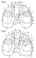
- FIG. 1 A handlebar 7 with straight parallel guide surfaces 9a, 10a is mounted with a pin 13 on a tibia platform 2 and rotatable about a pivot point M.
- the condyles 5, 6, which can only be seen in section, are mounted in bearing shells 3, 4 of the meniscus part and experience a lateral force P in a line of action a, which they transmit to the meniscus part 1, which in turn transmits this lateral force to the handlebar 7.
- the position of the meniscus part 1 shown in FIG. 1 corresponds to the foremost anterior position on the tibia platform.
- the overlapping area of the guide surfaces 9a, 9b and the guide surfaces 10a, 10b is displaced anteriorly by a distance b from the pivot point M of the pin 13 and a moment P 'b is generated which determines the reaction force K 1 at point B.
- the greatest lateral forces occur in the approximately extended position of the knee joint, so that large lateral forces and small radii of curvature at the contact points A and B coincide in this position.
- the handlebar 7 In the following exemplary embodiments according to the invention, the same information signs as in FIG. 1 are used. They differ with regard to their geometry by the design of the side guides 9a, 9b and 10a, 10b.
- the meniscus part 1 is shown in its anterior position.
- the distance b from the start of the guide surfaces 9b, 10b to the pivot point M of the handlebar 7 is 0.542 cm.
- the shortest distance between the guide surfaces 9b, 10b of the meniscus part is 1.35 cm.
- the side guides 9b, 10b of the meniscus part 1 are convexly curved and have a radius of curvature R 2 .
- the side guides 9a, 10a of the handlebar 7 are slightly concave and have a radius of curvature R 1 which is substantially larger than the radius of curvature R 2 .
- the overall play is so large that there is no jamming during the displacement of the meniscus part against posterior. The larger the radius of curvature R 1 , the lower the risk of jamming.
- the guide 8 is designed as a groove in the following cases. In principle, it could also be designed as an elongated hole.
- the play between the handlebar and the guide together with the size of the radii of curvature R 1 , R 2 and the position of the center points relative to R 1 and R 2 in the longitudinal direction of the associated guide surfaces, determines the location of the contact points A and B within the overlap of the guide surfaces 9a, 9b and 10a, 10b.
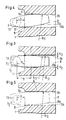
- FIGS. 3 and 5 show a further arrangement with a link 7 2 with convex guide surfaces and with a meniscus part 1 with straight, parallel guide surfaces 9b, 10b.
- the handlebars have a length of 2.75 cm and a maximum width of 1.33 cm.
- a correction possibility to reduce the inclination of the handlebar from the original 3 ° and to bring the contact points into the overlap of the guides is to reduce the play ⁇ .
- Another possibility of correction is to increase the radius of curvature R 11 .
- FIG. 5 shows the arrangement with the handlebar 72, the guide surfaces 9a, 10a of which are provided with a radius of curvature R 12 which, with an otherwise identical arrangement, leads to a contact point B within the overlap of the guide surfaces 10a, 10b.
- R 12 32.0 cm
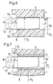
- the guide surfaces 9b, 10b of the meniscus part are no longer parallel and straight in comparison to FIG. 5, but are curved very little concavely.
- the center points of the radii of curvature R 1 of the meniscus part lie transversely to the guide surfaces 9b, 10b on their center line in the transverse direction.
- the handlebar is inclined in the anterior position of the meniscus part by 1.8 ° and contact points A, B are created within the overlap of the guide surfaces 9a, 9b and 10a, 10b.
- a guide groove 8 in one Keeping plastic such as polyethylene small can be an advantage be to produce this groove in an insert 14 made of metal and this to anchor in the meniscus part 1, as shown in FIG. Has such a groove the advantage that they do not change the distance between their guide surfaces 9b, 10b Sources still changed significantly due to temperature fluctuations.
- Another aspect is the multiple use of a handlebar 7 2 , as shown in FIG. 5, for meniscus parts 1 of different sizes and for tibia platforms 2 of different sizes, in order to be able to use a handlebar for different knee sizes.
- a handlebar 7 2 as shown in FIG. 5, for meniscus parts 1 of different sizes and for tibia platforms 2 of different sizes, in order to be able to use a handlebar for different knee sizes.
- it is advantageous for parts management for example with a "unitary link" with convex guide surfaces 9a, 10a and with straight parallel guide surfaces 9b, 10b of the meniscus part 1, to also cover the cases in which no canting occurs.
Landscapes
- Health & Medical Sciences (AREA)
- Orthopedic Medicine & Surgery (AREA)
- Physical Education & Sports Medicine (AREA)
- Cardiology (AREA)
- Oral & Maxillofacial Surgery (AREA)
- Transplantation (AREA)
- Engineering & Computer Science (AREA)
- Biomedical Technology (AREA)
- Heart & Thoracic Surgery (AREA)
- Vascular Medicine (AREA)
- Life Sciences & Earth Sciences (AREA)
- Animal Behavior & Ethology (AREA)
- General Health & Medical Sciences (AREA)
- Public Health (AREA)
- Veterinary Medicine (AREA)
- Prostheses (AREA)
Abstract
Description
- Fig. 1:
- schematisch aus dem Stand der Technik eine Draufsicht auf eine Tibiapolattform mit Lenker und Meniskus.
- Fig.2
- schematisch eine Draufsicht auf eine erfindungsgemässe Anordnung mit konvexen Führungsflächen am Lenker und mit konkaven Führungsflächen am Meniskusteil.
- Fig.3
- schematisch eine Draufsicht auf eine Anordnung mit zwei konvexen Lenkern, die unterschiedlich grosse Krümmungsradien aufweisen, wobei das Meniskusteil sich in der vorderen, d.h. anterioren Stellung befindet und ein gleiches Spiel /2 zwischen den Führungsflächen besteht.
- Fig.4
- schematisch die Anordnung von Fig.3 mit dem kleineren Krümmungsradius R11 der konvexen Führungsflächen des Lenkers.
- Fig.5
- schematisch die Anordnung von Fig.3 mit dem grösseren Krümmungsradius R12 der konvexen Führungsflächen des Lenkers.
- Fig.6
- schematisch eine Anordnung mit konvexen Führungsflächen des Lenkers und mit konkaven Führungsflächen des Meniskusteils, und
- Fig.7
- schematisch eine Anordnung mit konvexen Führungsflächen des Lenkers und mit konvexen Führungsflächen des Meniskusteils.
Claims (10)
- Künstliches Kniegelenk mit einem Meniskusteil (1), welches auf einer Tibiaplattform (2) verschiebbar gelagert ist, und mit einem relativ zur Tibiaplattform (2) drehbar gelagerten Lenker (7), der in eine Führung (8) des Meniskusteils eingreift, wobei der Lenker und das Meniskusteil (1) seitliche Führungsflächen (9a, 10a; 9b, 10b) zur Führung des Meniskusteils (1) aufweisen,
dadurch gekennzeichnet, dass die seitlichen Führungsflächen (9a, 10a) des Lenkers (7) und die zugehörigen Führungsflächen (9b, 10b) des Meniskusteils (1) unterschiedliche Krümmungsradien (R1; R2) aufweisen, die grösser als 10 cm sind, wobei die Summe der Reziproke der Krümmungsradien 1 / R1 + 1 / R2 kleiner als 0,2 cm-1 ist. - Künstliches Kniegelenk nach Anspruch 1, dadurch gekennzeichnet, dass die Krümmungsradien (R1, R2) grösser als 20 cm sind, wobei die Summe der Reziproke der Krümmungsradien 1 / R1 + 1 / R2 kleiner als 0,1 cm-1 ist.
- Künstliches Kniegelenk nach Anspruch 1 oder 2, dadurch gekennzeichnet, dass die Krümmungsradien (R1, R2) grösser als 30 cm sind, wobei die Summe der Reziproke der Krümmungsradien 1 / R1 + 1 / R2 kleiner als 0,067 cm-1 ist.
- Künstliches Kniegelenk nach einem der Ansprüche 1 bis 3, dadurch gekennzeichnet, dass die Führungsflächen (9a, 10a) des Lenkers (7) konvex und die Führungsflächen (9b, 10b) des Meniskus konkav oder geradlinig sind.
- Künstliches Kniegelenk nach einem der Ansprüche 1 bis 3, dadurch gekennzeichnet, dass die Führungsflächen (9b, 10b) des Meniskus konvex und die Führungsflächen des Lenkers konkav oder geradlinig sind.
- Künstliches Kniegelenk nach einem der Ansprüche 1 bis 5, dadurch gekennzeichnet, dass die Führungsflächen (9a, 10a) des Lenkers (7) metallisch und die Führungsflächen (9b, 10b) des Meniskus aus Kunststoff sind.
- Künstliches Kniegelenk nach einem der Ansprüche 1 bis 5, dadurch gekennzeichnet, dass die Führungsflächen (9a, 9b; 10a, 10b) von Lenker und Meniskus metallisch sind.
- Künstliches Kniegelenk nach einem der Ansprüche 1 bis 7, dadurch gekennzeichnet, dass der Drehpunkt M des Lenkers (7) in Längsrichtung von der Mitte des Lenkers betrachtet gegen posterior verschoben ist.
- Künstliches Kniegelenk nach einem der Ansprüche 1 bis 8, dadurch gekennzeichnet, dass verschieden grosse Meniski, die sich auch durch die Länge ihrer Führungsflächen (9b, 10b) unterscheiden, mit dem gleichen Lenker (7) kombinierbar sind.
- Künstliches Kniegelenk nach einem der Ansprüche 1 bis 9, dadurch gekennzeichnet, dass der Lenker einen Drehzapfen (13) aufweist, welcher in der Tibiaplattform gelagert ist.
Priority Applications (1)
| Application Number | Priority Date | Filing Date | Title |
|---|---|---|---|
| EP20000810598 EP1078612B1 (de) | 1999-08-10 | 2000-07-10 | Künstliches Kniegelenk |
Applications Claiming Priority (3)
| Application Number | Priority Date | Filing Date | Title |
|---|---|---|---|
| EP99810719 | 1999-08-10 | ||
| EP99810719 | 1999-08-10 | ||
| EP20000810598 EP1078612B1 (de) | 1999-08-10 | 2000-07-10 | Künstliches Kniegelenk |
Publications (2)
| Publication Number | Publication Date |
|---|---|
| EP1078612A1 true EP1078612A1 (de) | 2001-02-28 |
| EP1078612B1 EP1078612B1 (de) | 2008-05-28 |
Family
ID=26073944
Family Applications (1)
| Application Number | Title | Priority Date | Filing Date |
|---|---|---|---|
| EP20000810598 Expired - Lifetime EP1078612B1 (de) | 1999-08-10 | 2000-07-10 | Künstliches Kniegelenk |
Country Status (1)
| Country | Link |
|---|---|
| EP (1) | EP1078612B1 (de) |
Citations (1)
| Publication number | Priority date | Publication date | Assignee | Title |
|---|---|---|---|---|
| EP0529408A1 (de) | 1991-08-24 | 1993-03-03 | Aesculap Ag | Kniegelenkendoprothese |
-
2000
- 2000-07-10 EP EP20000810598 patent/EP1078612B1/de not_active Expired - Lifetime
Patent Citations (1)
| Publication number | Priority date | Publication date | Assignee | Title |
|---|---|---|---|---|
| EP0529408A1 (de) | 1991-08-24 | 1993-03-03 | Aesculap Ag | Kniegelenkendoprothese |
Also Published As
| Publication number | Publication date |
|---|---|
| EP1078612B1 (de) | 2008-05-28 |
Similar Documents
| Publication | Publication Date | Title |
|---|---|---|
| EP0406606B1 (de) | Kniegelenk-Endoprothese | |
| EP0488378B1 (de) | Kniegelenkendoprothese | |
| EP1321114B1 (de) | Schultergelenkprothese | |
| DE2744710C2 (de) | ||
| EP0728061B1 (de) | Schere, insbesondere friseurschere | |
| EP0672397B1 (de) | Tibiaplateau für eine künstliches Kniegelenk | |
| EP0724868B1 (de) | Gelenkprothese, insbesondere Kniegelenkprothese | |
| EP3837094B1 (de) | Vorrichtung zum unterstützen wenigstens eines armes eines benutzers | |
| EP2438889B1 (de) | Kniegelenkprothese | |
| EP0547476B1 (de) | Kniegelenkendoprothese | |
| EP1245204A2 (de) | Knieprothese | |
| CH686611A5 (de) | Kunstliches Kniegelenk. | |
| DE2005537B2 (de) | Gelenkprothese | |
| WO1997000053A1 (de) | Künstliches gelenk, insbesondere endoprothese zum ersatz natürlicher gelenke | |
| EP1524954B1 (de) | Knieprothese | |
| EP2259754B1 (de) | Knieendoprothese | |
| DE3039992A1 (de) | Endoprothetische knochengelenkvorrichtung insbesondere fuer das kniegelenk | |
| CH639735A5 (de) | Mechanischer kraftverstaerker. | |
| EP1849439A2 (de) | Knieprothesengelenk | |
| DE2221950A1 (de) | Kunstgliedkonstruktion | |
| EP0151724B1 (de) | Tibiateil für eine Kniegelenkprothese | |
| CH617584A5 (de) | ||
| DE3022668C2 (de) | Kniegelenkschlittenendoprothese | |
| EP1078612A1 (de) | Künstliches Kniegelenk | |
| DE3633098A1 (de) | Verbindungsvorrichtung zwischen einem stiefel und einem langlaufski |
Legal Events
| Date | Code | Title | Description |
|---|---|---|---|
| PUAI | Public reference made under article 153(3) epc to a published international application that has entered the european phase |
Free format text: ORIGINAL CODE: 0009012 |
|
| AK | Designated contracting states |
Kind code of ref document: A1 Designated state(s): AT BE CH CY DE DK ES FI FR GB GR IE IT LI LU MC NL PT SE |
|
| AX | Request for extension of the european patent |
Free format text: AL;LT;LV;MK;RO;SI |
|
| 17P | Request for examination filed |
Effective date: 20010731 |
|
| AKX | Designation fees paid |
Free format text: AT BE CH CY DE DK ES FI FR GB GR IE IT LI LU MC NL PT SE |
|
| RAP1 | Party data changed (applicant data changed or rights of an application transferred) |
Owner name: ZIMMER GMBH |
|
| RTI1 | Title (correction) |
Free format text: KNEE PROSTHESIS |
|
| GRAP | Despatch of communication of intention to grant a patent |
Free format text: ORIGINAL CODE: EPIDOSNIGR1 |
|
| GRAS | Grant fee paid |
Free format text: ORIGINAL CODE: EPIDOSNIGR3 |
|
| GRAA | (expected) grant |
Free format text: ORIGINAL CODE: 0009210 |
|
| AK | Designated contracting states |
Kind code of ref document: B1 Designated state(s): AT BE CH CY DE DK ES FI FR GB GR IE IT LI LU MC NL PT SE |
|
| REG | Reference to a national code |
Ref country code: GB Ref legal event code: FG4D Free format text: NOT ENGLISH |
|
| REG | Reference to a national code |
Ref country code: CH Ref legal event code: EP |
|
| REF | Corresponds to: |
Ref document number: 50015178 Country of ref document: DE Date of ref document: 20080710 Kind code of ref document: P |
|
| GRAC | Information related to communication of intention to grant a patent modified |
Free format text: ORIGINAL CODE: EPIDOSCIGR1 |
|
| REG | Reference to a national code |
Ref country code: IE Ref legal event code: FG4D Free format text: LANGUAGE OF EP DOCUMENT: GERMAN |
|
| PG25 | Lapsed in a contracting state [announced via postgrant information from national office to epo] |
Ref country code: FI Free format text: LAPSE BECAUSE OF FAILURE TO SUBMIT A TRANSLATION OF THE DESCRIPTION OR TO PAY THE FEE WITHIN THE PRESCRIBED TIME-LIMIT Effective date: 20080528 Ref country code: ES Free format text: LAPSE BECAUSE OF FAILURE TO SUBMIT A TRANSLATION OF THE DESCRIPTION OR TO PAY THE FEE WITHIN THE PRESCRIBED TIME-LIMIT Effective date: 20080908 |
|
| PG25 | Lapsed in a contracting state [announced via postgrant information from national office to epo] |
Ref country code: NL Free format text: LAPSE BECAUSE OF FAILURE TO SUBMIT A TRANSLATION OF THE DESCRIPTION OR TO PAY THE FEE WITHIN THE PRESCRIBED TIME-LIMIT Effective date: 20080528 |
|
| NLV1 | Nl: lapsed or annulled due to failure to fulfill the requirements of art. 29p and 29m of the patents act | ||
| REG | Reference to a national code |
Ref country code: IE Ref legal event code: FD4D |
|
| PG25 | Lapsed in a contracting state [announced via postgrant information from national office to epo] |
Ref country code: IE Free format text: LAPSE BECAUSE OF FAILURE TO SUBMIT A TRANSLATION OF THE DESCRIPTION OR TO PAY THE FEE WITHIN THE PRESCRIBED TIME-LIMIT Effective date: 20080528 Ref country code: DK Free format text: LAPSE BECAUSE OF FAILURE TO SUBMIT A TRANSLATION OF THE DESCRIPTION OR TO PAY THE FEE WITHIN THE PRESCRIBED TIME-LIMIT Effective date: 20080528 Ref country code: PT Free format text: LAPSE BECAUSE OF FAILURE TO SUBMIT A TRANSLATION OF THE DESCRIPTION OR TO PAY THE FEE WITHIN THE PRESCRIBED TIME-LIMIT Effective date: 20081028 Ref country code: SE Free format text: LAPSE BECAUSE OF FAILURE TO SUBMIT A TRANSLATION OF THE DESCRIPTION OR TO PAY THE FEE WITHIN THE PRESCRIBED TIME-LIMIT Effective date: 20080828 |
|
| PG25 | Lapsed in a contracting state [announced via postgrant information from national office to epo] |
Ref country code: MC Free format text: LAPSE BECAUSE OF NON-PAYMENT OF DUE FEES Effective date: 20080731 |
|
| PLBE | No opposition filed within time limit |
Free format text: ORIGINAL CODE: 0009261 |
|
| STAA | Information on the status of an ep patent application or granted ep patent |
Free format text: STATUS: NO OPPOSITION FILED WITHIN TIME LIMIT |
|
| 26N | No opposition filed |
Effective date: 20090303 |
|
| PG25 | Lapsed in a contracting state [announced via postgrant information from national office to epo] |
Ref country code: AT Free format text: LAPSE BECAUSE OF NON-PAYMENT OF DUE FEES Effective date: 20080710 |
|
| PG25 | Lapsed in a contracting state [announced via postgrant information from national office to epo] |
Ref country code: LU Free format text: LAPSE BECAUSE OF NON-PAYMENT OF DUE FEES Effective date: 20080710 |
|
| PG25 | Lapsed in a contracting state [announced via postgrant information from national office to epo] |
Ref country code: BE Free format text: LAPSE BECAUSE OF NON-PAYMENT OF DUE FEES Effective date: 20080731 Ref country code: CY Free format text: LAPSE BECAUSE OF FAILURE TO SUBMIT A TRANSLATION OF THE DESCRIPTION OR TO PAY THE FEE WITHIN THE PRESCRIBED TIME-LIMIT Effective date: 20080528 |
|
| PG25 | Lapsed in a contracting state [announced via postgrant information from national office to epo] |
Ref country code: GR Free format text: LAPSE BECAUSE OF FAILURE TO SUBMIT A TRANSLATION OF THE DESCRIPTION OR TO PAY THE FEE WITHIN THE PRESCRIBED TIME-LIMIT Effective date: 20080829 |
|
| PGFP | Annual fee paid to national office [announced via postgrant information from national office to epo] |
Ref country code: DE Payment date: 20130722 Year of fee payment: 14 |
|
| REG | Reference to a national code |
Ref country code: CH Ref legal event code: NV Representative=s name: DR. GRAF AND PARTNER AG INTELLECTUAL PROPERTY, CH |
|
| REG | Reference to a national code |
Ref country code: DE Ref legal event code: R119 Ref document number: 50015178 Country of ref document: DE |
|
| PG25 | Lapsed in a contracting state [announced via postgrant information from national office to epo] |
Ref country code: DE Free format text: LAPSE BECAUSE OF NON-PAYMENT OF DUE FEES Effective date: 20150203 |
|
| REG | Reference to a national code |
Ref country code: DE Ref legal event code: R119 Ref document number: 50015178 Country of ref document: DE Effective date: 20150203 |
|
| REG | Reference to a national code |
Ref country code: FR Ref legal event code: PLFP Year of fee payment: 17 |
|
| REG | Reference to a national code |
Ref country code: FR Ref legal event code: PLFP Year of fee payment: 18 |
|
| REG | Reference to a national code |
Ref country code: FR Ref legal event code: PLFP Year of fee payment: 19 |
|
| PGFP | Annual fee paid to national office [announced via postgrant information from national office to epo] |
Ref country code: IT Payment date: 20190620 Year of fee payment: 20 |
|
| PGFP | Annual fee paid to national office [announced via postgrant information from national office to epo] |
Ref country code: FR Payment date: 20190625 Year of fee payment: 20 |
|
| PGFP | Annual fee paid to national office [announced via postgrant information from national office to epo] |
Ref country code: CH Payment date: 20190624 Year of fee payment: 20 |
|
| PGFP | Annual fee paid to national office [announced via postgrant information from national office to epo] |
Ref country code: GB Payment date: 20190613 Year of fee payment: 20 |
|
| REG | Reference to a national code |
Ref country code: CH Ref legal event code: PL |
|
| REG | Reference to a national code |
Ref country code: GB Ref legal event code: PE20 Expiry date: 20200709 |
|
| PG25 | Lapsed in a contracting state [announced via postgrant information from national office to epo] |
Ref country code: GB Free format text: LAPSE BECAUSE OF EXPIRATION OF PROTECTION Effective date: 20200709 |