EP1078583A1 - Perfectionnement pour etui tournant - Google Patents
Perfectionnement pour etui tournant Download PDFInfo
- Publication number
- EP1078583A1 EP1078583A1 EP00410100A EP00410100A EP1078583A1 EP 1078583 A1 EP1078583 A1 EP 1078583A1 EP 00410100 A EP00410100 A EP 00410100A EP 00410100 A EP00410100 A EP 00410100A EP 1078583 A1 EP1078583 A1 EP 1078583A1
- Authority
- EP
- European Patent Office
- Prior art keywords
- rotating case
- cover
- case
- pivoting
- male
- Prior art date
- Legal status (The legal status is an assumption and is not a legal conclusion. Google has not performed a legal analysis and makes no representation as to the accuracy of the status listed.)
- Granted
Links
- 230000002093 peripheral effect Effects 0.000 claims description 14
- 230000000295 complement effect Effects 0.000 claims description 10
- 239000011324 bead Substances 0.000 claims description 8
- 239000002537 cosmetic Substances 0.000 claims description 6
- 230000000717 retained effect Effects 0.000 abstract 1
- 230000007246 mechanism Effects 0.000 description 3
- 238000010276 construction Methods 0.000 description 2
- 238000000926 separation method Methods 0.000 description 2
- 240000007594 Oryza sativa Species 0.000 description 1
- 235000007164 Oryza sativa Nutrition 0.000 description 1
- 102000015933 Rim-like Human genes 0.000 description 1
- 108050004199 Rim-like Proteins 0.000 description 1
- 230000000903 blocking effect Effects 0.000 description 1
- 235000013339 cereals Nutrition 0.000 description 1
- 239000006071 cream Substances 0.000 description 1
- 230000005489 elastic deformation Effects 0.000 description 1
- 238000000605 extraction Methods 0.000 description 1
- 238000002347 injection Methods 0.000 description 1
- 239000007924 injection Substances 0.000 description 1
- 210000002445 nipple Anatomy 0.000 description 1
- 230000003071 parasitic effect Effects 0.000 description 1
- 230000001681 protective effect Effects 0.000 description 1
- 235000009566 rice Nutrition 0.000 description 1
Images



Classifications
-
- A—HUMAN NECESSITIES
- A45—HAND OR TRAVELLING ARTICLES
- A45D—HAIRDRESSING OR SHAVING EQUIPMENT; EQUIPMENT FOR COSMETICS OR COSMETIC TREATMENTS, e.g. FOR MANICURING OR PEDICURING
- A45D40/00—Casings or accessories specially adapted for storing or handling solid or pasty toiletry or cosmetic substances, e.g. shaving soaps or lipsticks
- A45D40/12—Casings with provision for preventing undesired movement of the stick
Definitions
- the present invention relates to an improvement intended for rotary cases of the type used to contain products cosmetics such as lipstick or various lip creams. he relates more particularly to the construction of the fixing means between the case body and the closing cover.
- the present invention aims to solve the disadvantages mentioned above using simple, reliable and inexpensive means. Its purpose is to allow obtaining a rotating case whose product extraction mechanism cannot be accidentally activated or inadvertently when the case is closed, thus protecting the product from any untimely exit, preventing it from being damaged by the cover closing.
- the revolving case in particular for the cosmetic product of the invention, it is of the type comprising a base on which a pivoting body is pivotally mounted whose rotational movement relative to the base causes a cursor in longitudinal translation, said case also comprising a cover closure intended to be secured to the pivoting body by means of additional fixing, and is characterized in that the means of additional fixing allow the hood and the body pivoting along the longitudinal axis of the case, preventing translation between the two parts, and leave the cover free to rotate by relative to the body pivoting about this longitudinal axis.
- the fixing means complementary are constituted by a male fixing element located on the closing cover and a female fixing element arranged on the body swivel.
- the cover of closure includes in its enclosure an internal wall portion which extends down below its upper wall and which carries the element male fastening.
- the female fastening element consists by a peripheral rim located at the upper end of the wall peripheral forming the pivoting body and extending towards the interior of said body.
- the male element is formed by an annular bead.
- the male element is formed by clipping pins.
- the means additional fasteners consist of a fastening element female located on the closing cover and a male fastening element located on the pivoting body.
- the female element is constituted by an annular groove located at the lower end of the cover on the internal face of its peripheral wall and in that the male element is constituted by an annular bead arranged on the external face of the peripheral wall forming the body swivel.
- the rotating case of the invention is characterized in that the pivoting body and the cover of closure are made of plastic and in that the means of complementary fixing of the male element and the female element cooperate by clipping.
- this is characterized in that the closing cover comprises in its encloses an inner wall portion which at least partially carries the additional fixing means.
- FIGS 1a to 7 illustrate the preferred embodiment of the case turning point and execution variants thereof.
- Figure 1a shows in longitudinal section the body of the case. the case rotating in the unfolded position.
- Figure 1b shows in a view similar to Figure 1a, the body in the folded position.
- Figure 2 illustrates in longitudinal section the closure cover of the rotating case.
- Figure 3 illustrates in a view similar to Figure 2 a first variant of the closure cover.
- Figure 4 shows in longitudinal section the first mode of realization of the case rotating in the closed position.
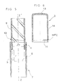
- Figure 5 illustrates in a view similar to Figure 1b a second embodiment of the case body.
- Figure 6 illustrates in longitudinal section the closure cover of the second embodiment of the rotating case.
- Figure 7 shows in a view similar to Figure 4 the second embodiment of the case rotating in the closed position.
- the rotating case bearing the general reference (1) is of the type constituted by a case body (2) which includes the mechanism itself and the product like for example lipstick, and by a closure cover (3) intended to be fixed to the case body (2).
- the body case (2) comprises a base (6) and a pivoting body (4) capable of pivot relative to the base to cause in a manner known per se, the longitudinal translational movement of a cursor (5) which carries the cosmetic product.
- the base (6) and the slider (5) form a single piece, however it could be otherwise and the cursor could be got independently of the base in a manner known per se.
- the closure cover (3) is intended to be secured to the case body (2) and more particularly to the pivoting body (4) thanks to complementary fixing means (MFC) arranged on the hood and on the pivoting body.
- MFC complementary fixing means
- additional fixing means (MFC) allow the closure cover (3) to be secured to the pivoting body (4) so as to allow the cover to rotate freely by relation to the pivoting body while preventing longitudinal translation between these two rooms.
- the fixing takes place directly between the cover and the pivoting body to make them integral without requiring of additional parts, the fixing means (MFC) being carried by said pivoting body and said cover.
- MFC fixing means
- the complementary fixing means are obtained by clipping between a male element (10) and a female element (11), the cooperation prevents longitudinal translation along the longitudinal axis (ZZ ') but leaves free rotation around this longitudinal axis to allow the closing cover (3) to rotate freely without causing the pivoting body (4) in rotation relative to the base (6).
- the cover (3) has the male fixing element (10), it is located on the external face (16) of an internal wall extension (12) which projects downwards (BA) in the enclosure of the cover from the upper wall (13) of said cover.
- the internal extension (12) is advantageously formed by a portion of cylindrical wall whose external diameter (D1) corresponds to the clearance of clipping ready to the internal diameter (D2) of the pivoting body (4).
- the element fixing male (10) is constituted by a peripheral annular bead arranged substantially at the end of the internal wall extension (12) as shown in Figure 2, it is intended to clip on the female element (11) arranged on the internal face of the pivoting body (4) and advantageously formed by an upper peripheral rim like the shows figure 1b and figure 4.
- the element female is therefore produced by a peripheral rim (11) located at the end upper of the cylindrical wall (9) forming the pivoting body (4) and extending radically inward of it.
- the male element (10) may have a different configuration and be formed by clip nipples also called grains of rice by example, which extend around the periphery of the wall extension internal (12).
- the male fastening element could be arranged on the inner face of the pivoting body while the female element would arranged on the internal extension of the hood without leaving the protective fields of the invention.
- the clipping is carried out advantageously thanks to the elastic deformation of the internal wall (12) of the cover (3) and / or to that from the end of the peripheral wall (9) of the pivoting body (4).
- these parts are made of plastic and can be made by injection for example.
- the internal wall of the closure cover could carry the female element and the bore of the body pivoting the male element without however, depart from the scope of the invention.
- the internal wall of the door closing cover at least in part the complementary fixing means (MFC), say either the male element or the female element.
- MFC complementary fixing means
- the internal wall (12) has a cylindrical shape completes and extends from the top wall of the hood.
- this wall could for example be formed of several portions of cylindrical walls or even have a different shape, it could also extend from the wall cylindrical external device of the hood and no longer from its wall higher without departing from the scope of the invention.
- the male and female fixing elements (10, 11) are arranged respectively on the external face of the wall (9) of the pivoting body (4) and on the internal face of the peripheral wall (14) of the cover (3).
- the element male is formed by an annular bead (10) located on the external face of the pivoting body (4) in the lower part thereof while the element corresponding female (11) is formed by an annular groove located in the inner face of the peripheral wall (14) of the cover (3) near the lower end of said cover.
- the groove (11) and the bead (10) have similar transverse profiles, they allow during their cooperation the rotation between the cover (3) and the pivoting body (4) which carries them while preventing their separation by longitudinal translation. This separation obtained by forcing the unlocking of these means of fixing in a manner known per se.
- the rotating case is consisting of three parts, namely a cover (3) a pivoting body (4) and a carrier assembly (20) formed by the base (6), the slider (5) and elements hinge (7) blocking the cursor in rotation relative to the base to allow its longitudinal movement in a manner known per se during the respective rotation between the pivoting body (4) and the base (6).
- the additional fixing means described in the invention could be used for cases where the assembly carrier is made in several pieces.
Landscapes
- Closures For Containers (AREA)
Abstract
Description
Claims (10)
- Etui tournant (1) notamment pour produit cosmétique du type comportant une embase (6) sur laquelle est montée pivotant un corps pivotant (4) dont le mouvement de rotation par rapport à l'embase entraíne un curseur (5) en translation longitudinale ,ledit étui comportant également un capot de fermeture (3) destiné à être solidarisé au corps pivotant (4) grâce à des moyens de fixation complémentaires (MFC) caractérisé en ce que les moyens de fixation complémentaires (MFC) permettent de rendre solidaire le capot (3) et le corps pivotant (4) selon l'axe longitudinal (ZZ') de l'étui, empêchant la translation respective entre les deux pièces, et laissent le capot (3) libre en rotation par rapport au corps pivotant (4) autour de cet axe longitudinal (ZZ').
- Etui tournant (1) selon la revendication 1 caractérisé en ce que les moyens de fixation complémentaires (MFC) sont constitués par un élément de fixation mâle (10) situé sur le capot de fermeture (3) et un élément de fixation femelle (11) disposé sur le corps pivotant (4).
- Etui tournant (1) selon la revendication 2 caractérisé en ce que le capot de fermeture (3) comprend dans son enceinte une portion de paroi interne (12) qui s'étend vers le bas (BA) à l'aplomb de sa paroi supérieure (13) et qui porte l'élément de fixation mâle (10).
- Etui tournant (1) selon la revendication 2 ou 3 caractérisé en ce que l'élément de fixation femelle (10) est constitué par un rebord périphérique (11) situé à l'extrémité supérieure de la paroi périphérique (9) formant le corps pivotant (4) et s'étendant vers l'intérieur dudit corps.
- Etui tournant (1) selon l'une quelconque des revendication 2 à 4 caractérisé en ce que l'élément mâle (10) est formé par un bourrelet annulaire.
- Etui tournant (1) selon l'une quelconque des revendication 2 à 4 caractérisé en ce que l'élément mâle (10) est formé par des tétons de clipsage.
- Etui tournant (1) selon la revendication 1 caractérisé en ce que les moyens de fixation complémentaires sont constitués par un élément de fixation femelle (11) situé sur le capot de fermeture (3) et un élément de fixation mâle (10) situé sur le corps pivotant (4).
- Etui tournant (1) selon la revendication 7 caractérisé en ce que l'élément femelle est constitué par une gorge annulaire (11) située à l'extrémité inférieure du capot (3) sur la face interne de sa paroi périphérique (14) et en ce que l'élément mâle (10) est constitué par un bourrelet annulaire disposé sur la face externe de la paroi périphérique (9) formant le corps pivotant (4).
- Etui tournant (1) selon l'une quelconque des revendication 2 à 8 caractérisé en ce que le corps pivotant (4) et le capot de fermeture (3) sont réalisés en matière plastique et en ce que les moyens de fixation complémentaires (MFC) de l'élément mâle (10) et de l'élément femelle (11) coopèrent par clipsage.
- Etui tournant (1) selon l'une quelconque des revendication précédentes caractérisé en ce que le capot de fermeture (3) comprend dans son enceinte une portion de paroi interne (12) qui porte au moins en partie les moyens de fixation complémentaires (MFC).
Applications Claiming Priority (2)
| Application Number | Priority Date | Filing Date | Title |
|---|---|---|---|
| FR9910822A FR2797754B1 (fr) | 1999-08-23 | 1999-08-23 | Perfectionnement pour etui tournant |
| FR9910822 | 1999-08-23 |
Publications (2)
| Publication Number | Publication Date |
|---|---|
| EP1078583A1 true EP1078583A1 (fr) | 2001-02-28 |
| EP1078583B1 EP1078583B1 (fr) | 2004-12-22 |
Family
ID=9549363
Family Applications (1)
| Application Number | Title | Priority Date | Filing Date |
|---|---|---|---|
| EP00410100A Expired - Lifetime EP1078583B1 (fr) | 1999-08-23 | 2000-08-21 | Perfectionnement pour etui tournant |
Country Status (5)
| Country | Link |
|---|---|
| US (1) | US6513536B1 (fr) |
| EP (1) | EP1078583B1 (fr) |
| DE (1) | DE60016852T2 (fr) |
| ES (1) | ES2235807T3 (fr) |
| FR (1) | FR2797754B1 (fr) |
Families Citing this family (3)
| Publication number | Priority date | Publication date | Assignee | Title |
|---|---|---|---|---|
| EP1269883B1 (fr) * | 2000-04-04 | 2005-08-03 | Shiro Takeda | Ensemble de maquillage et etui de stockage de produits cosmetiques |
| US7476048B2 (en) | 2006-09-07 | 2009-01-13 | L'oreal | Cap seal for a product dispensing applicator |
| IT202000005209A1 (it) * | 2020-03-11 | 2021-09-11 | Lumson Spa | Macchinetta di stick per labbra |
Citations (6)
| Publication number | Priority date | Publication date | Assignee | Title |
|---|---|---|---|---|
| US2309000A (en) * | 1940-11-26 | 1943-01-19 | Morrison Simon | Rotary lipstick holder |
| FR929031A (fr) * | 1946-06-14 | 1947-12-15 | Max Factor Hollywood Et France | Perfectionnements aux étuis pour rouge à lèvres |
| US2523457A (en) * | 1947-08-20 | 1950-09-26 | William G Thompson | Lipstick holder |
| FR985750A (fr) * | 1949-05-06 | 1951-07-23 | étui porte-fard | |
| FR1336295A (fr) * | 1962-07-19 | 1963-08-30 | Cartouche-recharge de rouge à lèvres ou produits analogues | |
| EP0865743A2 (fr) * | 1997-02-03 | 1998-09-23 | Techpack Espana S.L. | Récipient mécanique pour produits en forme de bâton |
Family Cites Families (3)
| Publication number | Priority date | Publication date | Assignee | Title |
|---|---|---|---|---|
| US2521140A (en) * | 1945-10-26 | 1950-09-05 | Bridgeport Metal Goods Mfg Co | Cosmetic holder |
| US3416868A (en) * | 1966-04-20 | 1968-12-17 | Int Silver Co | Lipstick or the like container |
| US6035866A (en) * | 1998-09-03 | 2000-03-14 | Eyelematic Manufacturing Co., Inc. | Pomade stick applicator with resilient sealing features |
-
1999
- 1999-08-23 FR FR9910822A patent/FR2797754B1/fr not_active Expired - Fee Related
-
2000
- 2000-08-21 EP EP00410100A patent/EP1078583B1/fr not_active Expired - Lifetime
- 2000-08-21 ES ES00410100T patent/ES2235807T3/es not_active Expired - Lifetime
- 2000-08-21 DE DE60016852T patent/DE60016852T2/de not_active Expired - Lifetime
- 2000-08-22 US US09/642,777 patent/US6513536B1/en not_active Expired - Fee Related
Patent Citations (6)
| Publication number | Priority date | Publication date | Assignee | Title |
|---|---|---|---|---|
| US2309000A (en) * | 1940-11-26 | 1943-01-19 | Morrison Simon | Rotary lipstick holder |
| FR929031A (fr) * | 1946-06-14 | 1947-12-15 | Max Factor Hollywood Et France | Perfectionnements aux étuis pour rouge à lèvres |
| US2523457A (en) * | 1947-08-20 | 1950-09-26 | William G Thompson | Lipstick holder |
| FR985750A (fr) * | 1949-05-06 | 1951-07-23 | étui porte-fard | |
| FR1336295A (fr) * | 1962-07-19 | 1963-08-30 | Cartouche-recharge de rouge à lèvres ou produits analogues | |
| EP0865743A2 (fr) * | 1997-02-03 | 1998-09-23 | Techpack Espana S.L. | Récipient mécanique pour produits en forme de bâton |
Also Published As
| Publication number | Publication date |
|---|---|
| DE60016852T2 (de) | 2005-12-08 |
| ES2235807T3 (es) | 2005-07-16 |
| FR2797754A1 (fr) | 2001-03-02 |
| DE60016852D1 (de) | 2005-01-27 |
| EP1078583B1 (fr) | 2004-12-22 |
| FR2797754B1 (fr) | 2001-12-21 |
| US6513536B1 (en) | 2003-02-04 |
Similar Documents
| Publication | Publication Date | Title |
|---|---|---|
| EP4003866B1 (fr) | Bouchon à ouverture sécurisée | |
| EP2298117B1 (fr) | Dispositif de conditionnement et de distribution d'un stick de produit, notamment d'un produit cosmétique | |
| FR2689485A1 (fr) | Dispositif de conditionnement, notamment pour produits cosmétiques. | |
| EP1458946B1 (fr) | Etui pour menottes | |
| FR2928629A1 (fr) | Dispositif de protection d'un recipient de produit, notamment d'un produit cosmetique. | |
| EP0633197A1 (fr) | Ensemble d'un récipient et d'un bouchage se verrouillant ensemble par rotation relative et son utilisation | |
| FR3100435A1 (fr) | Réceptacle d’un produit cosmétique et recharge pour un tel réceptacle | |
| WO2014170605A1 (fr) | Dispositif pour maintenir une portière d'un véhicule automobile dans une position entrebâillée | |
| EP4005430B1 (fr) | Mécanisme pour produit cosmétique, notamment un raisin de rouge à lèvres, et un réceptacle comportant un tel mécanisme | |
| WO2005088410A2 (fr) | Dispositif protege-couronne pour montre-bracelet | |
| EP1078583B1 (fr) | Perfectionnement pour etui tournant | |
| FR2604151A1 (fr) | Dispositif de bouchage du type a encliquettement et devissage | |
| FR2719558A1 (fr) | Cape inviolable destinée à la fermeture de récipients. | |
| EP0897679A1 (fr) | Boítier à charniere débrayable et à lèvre autojointante | |
| FR2955054A1 (fr) | Ensemble d'habillage de vehicule automobile muni d'une trappe d'occultation. | |
| EP1498993B1 (fr) | Accessoire pour goulotte à verrouillage automatique | |
| EP1014827B1 (fr) | Perfectionnement pour mecanisme d'etui tournant | |
| FR2789053A1 (fr) | Bouchon universel pour la fermeture de bouteilles deja debouchees, en particulier pour les bouteilles de vin ou de mousseux | |
| FR2989399A1 (fr) | Bras pour le deploiement et le repli d'un element souple de couverture et ensemble du type comprenant au moins un bras du genre precite et un dispositif d'eclairage | |
| FR3013524A1 (fr) | Fourreau a embout rotatif pour faisceau electrique apte a etre monte entre le chassis et un ouvrant d'un vehicule automobile | |
| CH682040A5 (en) | Bracelet for watch including small medicament container - has container incorporated in bracelet with clasp having appearance similar to that of other bracelet links | |
| EP1157937B1 (fr) | Dispositif d'obturation pour récipient de produits liquides | |
| FR2769005A1 (fr) | Capsule service pour recipient distributeur | |
| EP1897462A1 (fr) | Ensemble comprenant un boîtier cosmétique et un applicateur | |
| EP0948915A1 (fr) | Boíter pour produit, notamment sous forme d'un stick |
Legal Events
| Date | Code | Title | Description |
|---|---|---|---|
| PUAI | Public reference made under article 153(3) epc to a published international application that has entered the european phase |
Free format text: ORIGINAL CODE: 0009012 |
|
| AK | Designated contracting states |
Kind code of ref document: A1 Designated state(s): BE DE ES FR GB IT |
|
| AX | Request for extension of the european patent |
Free format text: AL;LT;LV;MK;RO;SI |
|
| 17P | Request for examination filed |
Effective date: 20010629 |
|
| AKX | Designation fees paid |
Free format text: BE DE ES FR GB IT |
|
| 17Q | First examination report despatched |
Effective date: 20020503 |
|
| APBZ | Receipt of observations in appeal recorded |
Free format text: ORIGINAL CODE: EPIDOSNOBA4E |
|
| APBH | Information on receipt of observation in appeal deleted |
Free format text: ORIGINAL CODE: EPIDOSDOBA4E |
|
| APBX | Invitation to file observations in appeal sent |
Free format text: ORIGINAL CODE: EPIDOSNOBA2E |
|
| APBZ | Receipt of observations in appeal recorded |
Free format text: ORIGINAL CODE: EPIDOSNOBA4E |
|
| APBT | Appeal procedure closed |
Free format text: ORIGINAL CODE: EPIDOSNNOA9E |
|
| GRAP | Despatch of communication of intention to grant a patent |
Free format text: ORIGINAL CODE: EPIDOSNIGR1 |
|
| GRAS | Grant fee paid |
Free format text: ORIGINAL CODE: EPIDOSNIGR3 |
|
| GRAA | (expected) grant |
Free format text: ORIGINAL CODE: 0009210 |
|
| AK | Designated contracting states |
Kind code of ref document: B1 Designated state(s): BE DE ES FR GB IT |
|
| REG | Reference to a national code |
Ref country code: GB Ref legal event code: FG4D Free format text: NOT ENGLISH |
|
| APAA | Appeal reference recorded |
Free format text: ORIGINAL CODE: EPIDOS REFN |
|
| REF | Corresponds to: |
Ref document number: 60016852 Country of ref document: DE Date of ref document: 20050127 Kind code of ref document: P |
|
| GBT | Gb: translation of ep patent filed (gb section 77(6)(a)/1977) |
Effective date: 20050405 |
|
| REG | Reference to a national code |
Ref country code: ES Ref legal event code: FG2A Ref document number: 2235807 Country of ref document: ES Kind code of ref document: T3 |
|
| APAH | Appeal reference modified |
Free format text: ORIGINAL CODE: EPIDOSCREFNO |
|
| PLBE | No opposition filed within time limit |
Free format text: ORIGINAL CODE: 0009261 |
|
| STAA | Information on the status of an ep patent application or granted ep patent |
Free format text: STATUS: NO OPPOSITION FILED WITHIN TIME LIMIT |
|
| 26N | No opposition filed |
Effective date: 20050923 |
|
| PGFP | Annual fee paid to national office [announced via postgrant information from national office to epo] |
Ref country code: BE Payment date: 20070821 Year of fee payment: 8 |
|
| PG25 | Lapsed in a contracting state [announced via postgrant information from national office to epo] |
Ref country code: BE Free format text: LAPSE BECAUSE OF NON-PAYMENT OF DUE FEES Effective date: 20080831 |
|
| PGFP | Annual fee paid to national office [announced via postgrant information from national office to epo] |
Ref country code: ES Payment date: 20100727 Year of fee payment: 11 |
|
| PGFP | Annual fee paid to national office [announced via postgrant information from national office to epo] |
Ref country code: DE Payment date: 20100824 Year of fee payment: 11 Ref country code: FR Payment date: 20100817 Year of fee payment: 11 |
|
| PGFP | Annual fee paid to national office [announced via postgrant information from national office to epo] |
Ref country code: GB Payment date: 20100804 Year of fee payment: 11 |
|
| PG25 | Lapsed in a contracting state [announced via postgrant information from national office to epo] |
Ref country code: IT Free format text: LAPSE BECAUSE OF NON-PAYMENT OF DUE FEES Effective date: 20090821 |
|
| PGFP | Annual fee paid to national office [announced via postgrant information from national office to epo] |
Ref country code: IT Payment date: 20100728 Year of fee payment: 11 |
|
| PGRI | Patent reinstated in contracting state [announced from national office to epo] |
Ref country code: IT Effective date: 20110616 |
|
| GBPC | Gb: european patent ceased through non-payment of renewal fee |
Effective date: 20110821 |
|
| REG | Reference to a national code |
Ref country code: FR Ref legal event code: ST Effective date: 20120430 |
|
| PG25 | Lapsed in a contracting state [announced via postgrant information from national office to epo] |
Ref country code: IT Free format text: LAPSE BECAUSE OF NON-PAYMENT OF DUE FEES Effective date: 20110821 |
|
| REG | Reference to a national code |
Ref country code: DE Ref legal event code: R119 Ref document number: 60016852 Country of ref document: DE Effective date: 20120301 |
|
| PG25 | Lapsed in a contracting state [announced via postgrant information from national office to epo] |
Ref country code: GB Free format text: LAPSE BECAUSE OF NON-PAYMENT OF DUE FEES Effective date: 20110821 Ref country code: FR Free format text: LAPSE BECAUSE OF NON-PAYMENT OF DUE FEES Effective date: 20110831 |
|
| REG | Reference to a national code |
Ref country code: ES Ref legal event code: FD2A Effective date: 20121207 |
|
| PG25 | Lapsed in a contracting state [announced via postgrant information from national office to epo] |
Ref country code: ES Free format text: LAPSE BECAUSE OF NON-PAYMENT OF DUE FEES Effective date: 20110822 |
|
| PG25 | Lapsed in a contracting state [announced via postgrant information from national office to epo] |
Ref country code: DE Free format text: LAPSE BECAUSE OF NON-PAYMENT OF DUE FEES Effective date: 20120301 |