EP1078560B1 - Card guide including air deflector means and air deflector means for a cooling card guide - Google Patents
Card guide including air deflector means and air deflector means for a cooling card guide Download PDFInfo
- Publication number
- EP1078560B1 EP1078560B1 EP99921555A EP99921555A EP1078560B1 EP 1078560 B1 EP1078560 B1 EP 1078560B1 EP 99921555 A EP99921555 A EP 99921555A EP 99921555 A EP99921555 A EP 99921555A EP 1078560 B1 EP1078560 B1 EP 1078560B1
- Authority
- EP
- European Patent Office
- Prior art keywords
- card
- air deflector
- card guide
- guide
- daughter
- Prior art date
- Legal status (The legal status is an assumption and is not a legal conclusion. Google has not performed a legal analysis and makes no representation as to the accuracy of the status listed.)
- Expired - Lifetime
Links
- 238000001816 cooling Methods 0.000 title abstract description 9
- 230000000712 assembly Effects 0.000 claims abstract description 12
- 238000000429 assembly Methods 0.000 claims abstract description 12
- 238000001125 extrusion Methods 0.000 claims description 16
- 238000000034 method Methods 0.000 claims description 13
- 230000007246 mechanism Effects 0.000 claims description 11
- 230000008878 coupling Effects 0.000 claims description 9
- 238000010168 coupling process Methods 0.000 claims description 9
- 238000005859 coupling reaction Methods 0.000 claims description 9
- 239000002131 composite material Substances 0.000 claims description 3
- 238000001746 injection moulding Methods 0.000 claims description 3
- 238000004519 manufacturing process Methods 0.000 claims description 3
- 239000000463 material Substances 0.000 claims description 3
- 239000007769 metal material Substances 0.000 claims description 3
- 239000004033 plastic Substances 0.000 claims description 3
- 238000005266 casting Methods 0.000 claims description 2
- 238000000465 moulding Methods 0.000 claims description 2
- 230000000116 mitigating effect Effects 0.000 abstract description 4
- 230000003068 static effect Effects 0.000 description 7
- 230000008901 benefit Effects 0.000 description 4
- 238000010276 construction Methods 0.000 description 3
- 238000007599 discharging Methods 0.000 description 3
- 230000001976 improved effect Effects 0.000 description 3
- 230000005465 channeling Effects 0.000 description 2
- 238000004891 communication Methods 0.000 description 2
- 230000006378 damage Effects 0.000 description 2
- 238000003780 insertion Methods 0.000 description 2
- 230000037431 insertion Effects 0.000 description 2
- 230000008093 supporting effect Effects 0.000 description 2
- 239000000853 adhesive Substances 0.000 description 1
- 230000001070 adhesive effect Effects 0.000 description 1
- 238000013459 approach Methods 0.000 description 1
- 238000010420 art technique Methods 0.000 description 1
- 239000004020 conductor Substances 0.000 description 1
- 238000009826 distribution Methods 0.000 description 1
- 230000001939 inductive effect Effects 0.000 description 1
- 238000005304 joining Methods 0.000 description 1
- 239000012811 non-conductive material Substances 0.000 description 1
- 238000003860 storage Methods 0.000 description 1
- 230000003685 thermal hair damage Effects 0.000 description 1
- 238000012546 transfer Methods 0.000 description 1
- 239000011800 void material Substances 0.000 description 1
Images


Classifications
-
- H—ELECTRICITY
- H05—ELECTRIC TECHNIQUES NOT OTHERWISE PROVIDED FOR
- H05K—PRINTED CIRCUITS; CASINGS OR CONSTRUCTIONAL DETAILS OF ELECTRIC APPARATUS; MANUFACTURE OF ASSEMBLAGES OF ELECTRICAL COMPONENTS
- H05K7/00—Constructional details common to different types of electric apparatus
- H05K7/14—Mounting supporting structure in casing or on frame or rack
- H05K7/1422—Printed circuit boards receptacles, e.g. stacked structures, electronic circuit modules or box like frames
- H05K7/1424—Card cages
- H05K7/1425—Card cages of standardised dimensions, e.g. 19"-subrack
-
- H—ELECTRICITY
- H05—ELECTRIC TECHNIQUES NOT OTHERWISE PROVIDED FOR
- H05K—PRINTED CIRCUITS; CASINGS OR CONSTRUCTIONAL DETAILS OF ELECTRIC APPARATUS; MANUFACTURE OF ASSEMBLAGES OF ELECTRICAL COMPONENTS
- H05K7/00—Constructional details common to different types of electric apparatus
- H05K7/14—Mounting supporting structure in casing or on frame or rack
- H05K7/1417—Mounting supporting structure in casing or on frame or rack having securing means for mounting boards, plates or wiring boards
- H05K7/1418—Card guides, e.g. grooves
-
- H—ELECTRICITY
- H05—ELECTRIC TECHNIQUES NOT OTHERWISE PROVIDED FOR
- H05K—PRINTED CIRCUITS; CASINGS OR CONSTRUCTIONAL DETAILS OF ELECTRIC APPARATUS; MANUFACTURE OF ASSEMBLAGES OF ELECTRICAL COMPONENTS
- H05K7/00—Constructional details common to different types of electric apparatus
- H05K7/20—Modifications to facilitate cooling, ventilating, or heating
- H05K7/20009—Modifications to facilitate cooling, ventilating, or heating using a gaseous coolant in electronic enclosures
Definitions
- Modern backplanes also referred to as motherboards, serve as a communication medium for the exchange of electronic signals between a plurality of daughter cards.
- Circuitry on each daughter card generates communication signals, which are distributed to connectors mounted along an edge of the daughter card.
- Daughter card connectors mate with a corresponding set of backplane connectors typically arranged in equidistant rows on the backplane for providing interconnect and distribution of signals therebetween.
- a chassis houses the backplane, daughter cards, and corresponding connectors.
- the chassis frame includes side panels and cross members, also referred to as extrusion rails.
- Card guides mounted on the extrusion rails run from the front to the rear of the chassis to guide the daughter cards into proper alignment with corresponding backplane connectors.
- Each daughter card position in the chassis is referred to as a card slot.
- the relative positioning of the card guides with respect to the mother board is critical, since the relative positioning determines how well the daughter card connectors align with the motherboard connectors during daughter card insertion. Consequently, motherboard alignment has traditionally required special tooling and procedures, and has been a tedious and time-consuming aspect of chassis assembly.
- daughter cards to be inserted into a motherboard chassis assembly may accumulate a significant static charge during storage and handling. This static charge must be discharged prior to electrically coupling the daughter card to the system via the motherboard connector, so as to prevent ESD damage to the system.
- the front panel assembly of a daughter card may include a number of cable connectors electrically coupled to external cables. Such cables and cable connectors may also provide a source of significant static charge which must be discharged to prevent ESD damage to the system.
- a popular means for inducing heat transfer is a cooling apparatus which forces a volume of cooled air through the chassis.
- the cooled air removes heat from the electrical components by means of thermal convection.
- the resulting warmed air is ventilated, or otherwise cooled and re-circulated.
- United States Patent Number 4,750,088, issued June 7, 1988 addresses this issue by providing a number of air deflectors having a wedge-shaped cross section.
- the deflectors are extruded members mounted across the top and bottom portions of the chassis, parallel to the extrusion rails, for directing cooling air into marginal areas of the daughter cards, proximal to the extrusion rails.
- this configuration complicates construction of the chassis by requiring additional hardware, which, in turn, lengthens the time and cost for production of the chassis assembly.
- the present invention relates to card guides, and more particularly to card guides which optimize the flow of forced cooling air, provide for self alignment to a host motherboard and provide for integrated ESD (Electrostatic Discharge) hazard mitigation.
- the present invention is directed to a card guide configured to maximize air flow across circuit boards mounted in a card cage in a manner which mitigates and/or eliminates regions of marginal air flow.
- circuitry can be populated on the daughter card in regions proximal to the extrusion rails, allowing for more efficient use of daughter card surface area.
- the present invention achieves this result in a manner which overcomes the limitations of the prior art. Specifically, air deflectors are incorporated into the body of the improved card guides, and the improved card guides are mounted to the chassis in a manner similar to the manner in which standard card guides are mounted. Unlike the prior art technique described above, additional hardware is not needed to redirect air flow about the extrusion rails and construction of the chassis is simplified.
- a card guide in accordance with the present invention is adapted for mounting to a circuit card chassis having extrusion rails or cross members.
- the card guide is further adapted for channeling a daughter card toward a motherboard assembly, so as to ensure proper registration of the daughter card connector with a motherboard connector.
- the card guide comprises an elongated body having a groove along its longitudinal axis for receiving the edge of a circuit card.
- the body is adapted for mounting to the extrusion rails.
- At least one air deflector is laterally coupled to the body, and extends in a direction substantially transverse to the longitudinal axis for redirecting incident air flow about the rail.
- the portion of the card guide having the groove along the longitudinal axis has a substantially "Y" shaped cross section to minimize the resistance presented by the card guide to incident air flow.
- the air deflector is integral with the card guide.
- the air deflector is preferably arcuate in cross section to optimize the efficiency of air flow. Fabrication of the card guide may be accomplished via injection molding techniques, or by other techniques known in the art.
- Standard mounts are preferably included at opposite ends of the card guide body for mounting the card guide to the extrusion support rails. Additional air deflectors, integral with the mounts, may also be included. Mounting features of the mounts may include a latching mechanism which extends transversely from the body of the card guide, and fixedly engages a corresponding aperture in the support rail.
- the body of the card guide includes an ESD clip having a base, a wiper blade and a barrel receptacle, all three of which are electrically conductive and electrically coupled to one another.
- the base of the ESD clip includes a terminal for electrically coupling to the extrusion support rail.
- the wiper blade extends through the body into the groove along the longitudinal axis. so as to facilitate electrical coupling to a conductive edge of the daughter card.
- the barrel receptacle is disposed adjacent to and coaxial with a guide aperture in the card guide body. When a daughter card is inserted into the chassis and mates with the motherboard, the barrel receptacle receives and electrically couples to an electrically conductive guide pin fixedly attached to a front panel of the daughter card.
- the body of the card guide includes an alignment pin, fixedly attached to an end of said body proximal to the motherboard assembly.
- the alignment pin extends from the body in a direction substantially parallel to the longitudinal axis, and is operative to engage a corresponding aperture in said motherboard, so as to substantially align the card guide to the motherboard.
- the present invention is directed to an air deflector assembly existing as a stand-alone unit, not associated with any card guide.
- Such an air deflector assembly may be used to redirect air flow at unused or "expansion" portions of the card cage.
- Standard mounts are preferably included at opposite ends of the air deflector assembly for mounting the assembly to the extrusion support rails in the same mounting facilities used by the card guides.
- the air deflector assembly includes an interconnection mechanism that allows multiple air deflector assemblies to be stacked; i.e., connected in series or tandem configuration such that air flow may be redirected about larger areas of the card cage than for a single card slot position.
- the present invention is directed to a card guide mount for mounting a card guide assembly to a support rail of a daughter card chassis.
- the card guide mount includes a mounting feature having a latching mechanism that is operative to fixedly engage a corresponding aperture in the support rail, an interconnection feature for fixedly engaging a card guide rail having a longitudinal axis. and at least one air deflector extending from the body, for redirecting incident air flow.
- the card guide rail includes an elongated body having a groove disposed substantially parallel to the longitudinal axis for receiving an edge of a daughter card.
- the air deflector may be substantially arcuate or wedged shaped in cross-section.
- the interconnection feature includes a tail piece extending from the card guide mount along an axis collinear with the guide rail longitudinal axis, and the tail piece fixedly engages a passage disposed within the guide rail along the longitudinal axis.
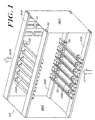
- FIG. 1 is a perspective view of a card cage 40 including card guides 20A, 20B configured with lateral air deflectors 26 in accordance with the present invention.
- the card cage 40 comprises a substantially rectangular frame including a pair of opposing side panels 36A. 36B held in spaced, parallel relationship and coupled by means of upper and lower cross members 30A, 30B.
- a plurality of upper and lower card guides 20A, 20B are captively held, in a manner standard in the art, between front and rear cross member support rails 30A, 30B as shown in FIG. 1.
- the card guides 20A, 20B include a longitudinal groove 22 adapted to receive and align an inserted daughter card with backplane connector rows 41 at the rear of the card cage 40.
- cooling air is pumped through the card cage 40 in the direction of arrow 42A.
- the cooling air 42A enters the lower portion of the card cage 40 between lower card guides 20B and about front and rear cross members 30B.
- the cooled air passes across the surface of the inserted daughter cards (not shown) and exits at the top portion of the card cage between upper card guides 20A and about front and rear upper cross members 30A in the direction of arrow 42B.
- the released air 42B warmed by heat energy extracted from the daughter card components, is re-circulated and cooled, or otherwise vented.
- the cross members 30A, 30B comprise extruded members, each member having a row of longitudinally-extending holes that are sized to receive screws 44 for mounting to side panels 36A, 36B.
- the cross members 30A, 30B include a series of evenly spaced apertures or sockets, in accordance with well-known configurations, adapted to captively secure card guides 20A, 20B and to ensure proper spacing and alignment of the card guides.
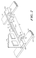
- FIG. 2 A close-up perspective illustration of a card guide 20 in accordance with a preferred embodiment of the present invention is illustrated in FIG. 2.
- the card guide 20 includes an elongated body 21 having a groove 22 along a longitudinal axis of the body 21.
- the groove 22 is adapted for receiving the edge of an inserted daughter card 32.
- Mounts 24A, 24B shown integral with the body 21 in this configuration, are included for mounting the card guide 20 to the cross members 30A, 30B.
- the mounts 24A and 24B may be modular, and therefore separable from the body 21.
- the card guide 20 further includes arcuate inner deflectors 26 and outer deflectors 28.
- Each pair of inner and outer deflectors 26, 28 respectively form a channel for redirecting incident air flow 42A, as shown in arrow 42B, toward regions of the daughter card which otherwise would be blocked by the air flow.
- the inner deflectors 26 extend laterally from the body 21, while the outer deflectors 28 are formed on the face of the mounts 24A, 24B as shown.
- the outer deflectors 28 may also extend laterally from the body 21.
- a number of deflectors 26, 28 may be positioned along the length of the body to redirect air flow, as needed.
- the card guide body 21 preferably has a substantially Y-shaped cross-sectional profile including a narrow head 25A and a wide base 25B. Such a profile provides minimal resistance to air flow and therefore allows for increased cooling of components.
- the advantages of the Y-shaped profile card guides are fully described in U.S. Patent Number 4,750,088.
- the card guide body 21 may also include a substantially "V" shaped or wedged shaped cross section, or other aerodynamic cross section known to those in the art.
- FIG. 3A is a front view of air flow across a daughter card 32 mounted in a chassis using card guides 20A, 20B in accordance with the prior art.
- Incident cooling air 42A flows about cross members 30A and 30B and past lower card guide 20B. This results in air turbulence which generates regions of marginal air flow 34, also referred to as "hot regions" proximal to the lower and upper cross members 30B, 30A.
- FIG. 3B is a front view of a configuration employing card guides 20A, 20B in accordance with the present invention.
- Incident air 42A is redirected by air deflectors 26, 28 into the regions 34 proximal to the cross members 30B, mitigating and/or eliminating turbulence proximal to the extrusion rails.
- the air deflectors 26, 28 promote air flow through regions 34 and mitigate turbulence. Components 53 populated in those regions 34 can therefore be properly cooled, allowing for efficient use of daughter card surface area.
- a card guide is provided which maximizes air flow across circuit boards mounted in a card cage in a manner which mitigates and/or eliminates regions of marginal air flow.
- Preferred card guide dimensions are defined in IEEE Mechanical Specification Draft 5.0 P1 101.10, based on a universal standard set forth for well known VME 64 Extension and Compact PCI configuration.
- the card guide of the present invention may comprise a guide of width 0.8 inches at its widest point, designed for a printed circuit card of 160 mm in length.
- the air deflector may be of a size ranging, for example, between 0.2 inches and 0.4 inches in width.
- the deflector preferably comprises a blade having inner and outer arcuate faces which preferably are parallel and of a radius between 0.35 and 0.5 inches.
- the arc is preferably 30 degrees to 90 degrees.
- the deflector may be configured in a wedge shape, as shown in U.S. Patent No. 4,750,088. Other deflector arrangements are applicable.
- the card guides are fabricated from a relatively rigid plastic material, although in other embodiments the card guides may be fabricated from metal or composite materials known to those in the art.
- the card guides are preferably fabricated via injection molding techniques known to those in the art, although other techniques such as alternative molding, casting, stamping and extrusion may also be utilized to fabricate the card guides.
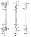
- FIGs. 4, 5, 6, 7, 8, and 9 provide various views of a preferred embodiment of the card guide 20.
- FIG. 4 illustrates a view of the face of the card guide 20 along which the longitudinal groove 22 is disposed, and thus is adjacent to the inserted daughter card.
- FIG. 5 illustrates a view of the card guide 20 consistent with rotating the card guide 20 shown in FIG. 4 180 degrees about an axis collinear with the longitudinal groove 22.
- the face of the card guide 20 shown in FIG. 4 is adjacent to the cross members 30A, 30B (see FIGs. 1-3, above).
- the view in FIG. 5 also illustrates the integral card guide mounting clips 62 which latch into the apertures of the cross members 30A and 30B.
- FIG. 4 illustrates a view of the face of the card guide 20 along which the longitudinal groove 22 is disposed, and thus is adjacent to the inserted daughter card.
- FIG. 5 illustrates a view of the card guide 20 consistent with rotating the card guide 20 shown in FIG. 4 180 degrees about an axis collinear with the
- FIG. 6 illustrates the face of the card guide 20 from which the air deflectors 26 perpendicularly extend. This view also illustrates an end view of the mounting clips 62.
- FIG. 7 illustrates a view of the card guide consistent with rotating the card guide as shown in FIG. 6 180 degrees about an axis collinear with the longitudinal groove 22.
- FIG. 8 illustrates an end view of the card guide 20. This view shows a round alignment aperture 104 and three square keying apertures 106. Key pins may be inserted into one or more of the three square keying apertures 106.
- the key pins are offset to one side, so that when they are inserted in a specific manner (as the offset can be in any of 4 positions), a particular card slot can be protected from the insertion of a module card into an incorrect slot.
- the round alignment aperture 104 has utility both as a socket for a fixedly attached alignment pin 120, and also as a receptacle for a guide pin mounted to a front panel of the daughter card; both uses are described in more detail hereinafter.
- the card guide 20 is symmetrical about a plane which perpendicularly intersects an axis which is collinear with the longitudinal groove 22, at a point which exactly bisects the length of the groove 22.
- FIG. 8 a view of the opposite end of the card guide 20 is a mirror image of the view shown in FIG. 8.
- FIG 9 illustrates an end of the card guide 20, tilted at an angle of approximately 45 degrees. This view shows the apertures 104 and 106 at the end of the card guide, along with a view of the cavity 102 within the mounts 24A and 24B.
- FIG. 10 shows a perspective view of an ESD clip 110.
- the ESD clip 110 provides means for dissipating static charge accumulated on a daughter card, prior to the daughter card engaging the motherboard.
- the end of the card guide 20 distal to the motherboard includes a cavity 102 which houses the ESD clip 100.
- One side of the cavity 102 (which corresponds to the outward, end face of the card guide) includes a round guide pin aperture 104 and three square keying pin apertures 106.
- the side of the cavity which is adjacent to the longitudinal groove 22 includes a square aperture 108 which extends through the card guide and into the longitudinal groove shown in FIG. 4.
- the ESD clip 110 includes three ESD components; a base 112, a wiper blade 114 and a barrel receptacle 116, all of which are electrically conductive and electrically coupled to one another.
- the base 112, wiper blade 114 and barrel receptacle 116 are fabricated from a single piece of conductive material, although other embodiments may include non-conductive materials which provide mechanical support for separate, electrically conductive ESD components.
- the base of the ESD clip is electrically coupled to the cross member 30, which provides a current sink for the electrostatic charge accumulated on the daughter card.
- the wiper blade 114 extends through the card guide 20 and into the longitudinal groove 22 (see FIG. 4) which guides the daughter card into the card cage. As the daughter card is inserted into the groove 22 of the card guide 20, a conductive strip located at the edge of the daughter card makes electrical contact with the wiper blade 114, so that a static charge built up on the daughter card may discharge from the conductive strip to the cross members 30 via the wiper blade 114 and base 112 of the ESD clip 110, as required by IEEE 1101.10.
- the barrel receptacle 116 is disposed about a receptacle axis 118.
- the barrel receptacle 116 is positioned adjacent to an alignment aperture 104 in the front card guide face (see FIG. 8), such that the receptacle axis 118 is collinear with the axis of the alignment aperture 104.
- the axis of the alignment hole 104 intersects the center of the alignment aperture 104 and is perpendicular to the radius of the alignment aperture 104.
- a front panel guide pin fixedly attached and electrically coupled to the daughter card front panel travels along a path which is approximately collinear with the receptacle axis 118.
- the front panel guide pin travels through the alignment hole and electrically couples to the barrel receptacle 116.
- FIG. 11 is a perspective view of an alignment pin 120 fixedly attached to a card guide 20, in accordance with the present invention.
- the alignment pin 120 is fixedly attached to an end of the card guide body proximal to the motherboard assembly, and extends from the body in a direction substantially parallel to the longitudinal axis of the card guide body.
- the alignment pin 120 is press-fit, in a manner known to those in the art, into the alignment aperture 104.
- the alignment pin 120 engages a corresponding aperture in said motherboard, so as to substantially align the card guide to the motherboard without having to resort to traditional time consuming alignment procedures.
- the connectors of daughter cards inserted into the chassis via the card guides will substantially align to the corresponding motherboard connectors.
- the embodiment of the invention described above includes individual, discrete card guides having integral air deflectors
- other embodiments may include two or more card guides joined by one or more elongated air deflectors having an arcuate cross section, forming an integral, multiple card guide unit 130 as shown in FIG. 12.
- the multiple card guides may be joined by other means, such as integral or discrete cross-members with the elongated air deflectors being merely attached to the multiple card guides, rather than structurally joining the card guides.
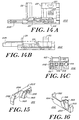
- a modular card guide 200 includes three distinct components; a first mounting bracket and deflector assembly 202, a second mounting bracket and deflector assembly 204, and a elongated guide rail 206.
- the features of the first and second mounting bracket and deflector assemblies 202 and 204 are substantially identical to the bracket/deflector features described in FIGs 4-9 for the single-component card guide 20.
- the card guide rail 206 preferably has a substantially Y-shaped cross-sectional profile including a narrow head 25A and a wide base 25B, as described herein for the card guide body 21.
- the length of the elongated guide rail 206 is not fixed, but rather is selected to suit a particular application.
- FIG. 13A illustrates an exploded perspective view of the components of a modular version of the card guide 200 and FIG. 13B illustrates a second perspective view of the mounting bracket and deflector assembly 202.
- one end of the card guide rail 206 attaches to the first mounting bracket and deflector assembly 202 and the opposite end of the card guide rail 206 attaches to the second mounting bracket and deflector assembly 204.
- a tail piece 208 is inserted into a channel 210 that exists within the guide rail 206.
- the rail 206 attaches to the mounting assemblies 202 and 204 by press fit, adhesive or by other methods known to those in the art. FIGs.
- FIG. 13A illustrates a front, side and end view, respectively, of the first mounting bracket and deflector assembly 202.
- the second bracket 204 is symmetrical with the first bracket 202, such that the first bracket 202 and the second bracket 204 are consistent with the two ends of the card guide 20 shown in FIG. 4,
- the embodiment of FIG. 13A offers the additional advantage of using the same two mounting brackets and deflector assemblies 202 and 204 to form a card guide of nearly any length by selecting an appropriate length for the elongated guide rail 206.
- an extension deflector assembly 302 may be used in an expansion slot of a card cage 40 (see FIG. 1) where no card guide is installed; i.e., at a portion of the card cage 40 where no daughter card circuit module is to be present.
- the void that results from the absence of a card guide may cause or contribute to undesirable air flow patterns within the card cage.
- the extension deflector assembly 302 includes a mounting base 325, at least one mounting clip 362, an inner deflector 326, an outer deflector 328, a latching mechanism 332 and a supporting sidewall 334.
- the supporting sidewall 334 supports and anchors the inner deflector 326 to the mounting base 325.
- the mounting clip 362 attaches to a cross member 30A or 30B in the same way as described herein for the various card guide embodiments.
- the extension deflector assembly 302 provides the same air channeling function that the card guide 20 described herein, such that a more predictable and desirable air flow pattern may be achieved.
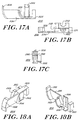
- FIG. 15 illustrates a first perspective view
- FIG. 16 illustrates a second perspective view of the extension deflector assembly 302.
- FIGs. 17A, 17B and 17C illustrate a front, side and end view, respectively, of the extension deflector assembly 302.
- FIG. 18A illustrates a first perspective view
- FIG. 18B illustrates a second perspective view of the a corresponding, symmetrical extension deflector assembly 304.
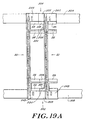
- the first extension assembly 302 may be used alone or in conjunction with second extension assembly 304, wherein the first assembly 302 is mounted to a cross member 30A (e.g., adjacent to mount 24B as shown in FIG. 19A) and the second assembly 304 is mounted to a cross member 30B (i.e., adjacent to mount 24A as shown in FIG. 19A).
- the latching mechanism 332 attaches (via press fit, "snap-locking," or other method known to those in the art) to a latching protrusion 60 on the mounting bracket 24A or 24B of the single piece card guide 20 (as shown in FIGs. 5 and 6) or on the modular mounting bracket and deflector assembly 202 or 204 (as shown in FIGs.
- extension deflector 302 or 304 may be used to secure to a card guide assembly.
- the extension deflector assembly 304 effectively extends the surfaces of the deflectors 26 and 28 of the card guide 20 so as to minimize air flow discontinuities.
- the extension deflector assemblies 302 and 304 are narrower than the card guide deflector assemblies. The utility of this relationship is that one or more extension deflector assemblies may be used to fill a gap between card guide positions that is not an integral number of card guide widths, ensuring a continuous deflector surface between card guide positions.
- a plurality of extension deflectors 302 may be combined to form a larger deflector assembly via press fitting, snap-locking, or other method known in the art) to one another rather than to card guides, as shown in FIG. 19B.
- the extension assemblies 302 and 304 may include a latching protrusion 60 (not shown on the illustrated embodiment) similar to the protrusions described herein for the card guide mounting components, or the latching mechanism 332 of an extension assembly 302 or 304 may attach to the mounting clip 362 of another extension assembly 302 or 304, respectively.
Landscapes
- Engineering & Computer Science (AREA)
- Microelectronics & Electronic Packaging (AREA)
- Physics & Mathematics (AREA)
- Thermal Sciences (AREA)
- Mounting Of Printed Circuit Boards And The Like (AREA)
- Cooling Or The Like Of Electrical Apparatus (AREA)
- Motor Or Generator Cooling System (AREA)
- Looms (AREA)
Applications Claiming Priority (5)
| Application Number | Priority Date | Filing Date | Title |
|---|---|---|---|
| US94179 | 1987-09-04 | ||
| US8562798P | 1998-05-15 | 1998-05-15 | |
| US09/094,179 US6381147B1 (en) | 1998-05-15 | 1998-06-09 | Card guide including air deflector means |
| PCT/US1999/009445 WO1999060834A1 (en) | 1998-05-15 | 1999-04-30 | Card guide including air deflector means and air deflector means for a cooling card guide |
| US85627P | 2008-08-01 |
Publications (2)
| Publication Number | Publication Date |
|---|---|
| EP1078560A1 EP1078560A1 (en) | 2001-02-28 |
| EP1078560B1 true EP1078560B1 (en) | 2003-07-02 |
Family
ID=26772922
Family Applications (1)
| Application Number | Title | Priority Date | Filing Date |
|---|---|---|---|
| EP99921555A Expired - Lifetime EP1078560B1 (en) | 1998-05-15 | 1999-04-30 | Card guide including air deflector means and air deflector means for a cooling card guide |
Country Status (6)
| Country | Link |
|---|---|
| EP (1) | EP1078560B1 (enExample) |
| JP (1) | JP4674314B2 (enExample) |
| AT (1) | ATE244499T1 (enExample) |
| AU (1) | AU3873999A (enExample) |
| CA (1) | CA2330640C (enExample) |
| DE (1) | DE69909289T2 (enExample) |
Families Citing this family (1)
| Publication number | Priority date | Publication date | Assignee | Title |
|---|---|---|---|---|
| US9485851B2 (en) * | 2014-03-14 | 2016-11-01 | Sandisk Technologies Llc | Thermal tube assembly structures |
-
1999
- 1999-04-30 CA CA002330640A patent/CA2330640C/en not_active Expired - Fee Related
- 1999-04-30 JP JP2000550314A patent/JP4674314B2/ja not_active Expired - Fee Related
- 1999-04-30 DE DE69909289T patent/DE69909289T2/de not_active Expired - Lifetime
- 1999-04-30 EP EP99921555A patent/EP1078560B1/en not_active Expired - Lifetime
- 1999-04-30 AU AU38739/99A patent/AU3873999A/en not_active Abandoned
- 1999-04-30 AT AT99921555T patent/ATE244499T1/de not_active IP Right Cessation
Also Published As
| Publication number | Publication date |
|---|---|
| AU3873999A (en) | 1999-12-06 |
| DE69909289T2 (de) | 2004-02-12 |
| JP2002516494A (ja) | 2002-06-04 |
| DE69909289D1 (de) | 2003-08-07 |
| CA2330640A1 (en) | 1999-11-25 |
| EP1078560A1 (en) | 2001-02-28 |
| ATE244499T1 (de) | 2003-07-15 |
| JP4674314B2 (ja) | 2011-04-20 |
| CA2330640C (en) | 2007-06-12 |
Similar Documents
| Publication | Publication Date | Title |
|---|---|---|
| US6381147B1 (en) | Card guide including air deflector means | |
| US6377470B1 (en) | Card guide including air deflector means and air deflector means for a cooling card guide | |
| US10257955B2 (en) | Cable backplane system having individually removable cable connector assemblies | |
| US6935868B1 (en) | Adjustable-width, dual-connector card module | |
| US6594148B1 (en) | Airflow system | |
| US9209539B2 (en) | Backplane or midplane communication system and connector | |
| CN104244661B (zh) | 用于电缆背板系统的间隔件 | |
| US6064575A (en) | Circuit module assembly | |
| US6166919A (en) | Casing mountable filler module | |
| US12158627B2 (en) | High speed network device with orthogonal pluggable optics modules | |
| US6646890B1 (en) | Mounting of mezzanine circuit boards to a base board | |
| US6230541B1 (en) | Cardcage for circuit cards | |
| US20080207029A1 (en) | Low profile high current power connector with cooling slots | |
| US20040037054A1 (en) | Card cage system | |
| US20090017681A1 (en) | Connector with uniformly arrange ground and signal tail portions | |
| JP2008501200A (ja) | モジュラブレードシャーシ用の再構成可能な気流ディレクタ | |
| US6582250B2 (en) | Connector module organizer | |
| US6396690B1 (en) | PCI card guide support bracket | |
| CN110419148A (zh) | 用于通信系统的电路卡组件 | |
| IE66396B1 (en) | Tiered socket assembly with integral ground shield | |
| US6411520B1 (en) | Modular equipment frame and modules | |
| CN104582361B (zh) | 具有安装块的电缆背板系统 | |
| ES2395037T3 (es) | Cuña de bloqueo para módulo de tarjeta de circuito electrónico | |
| US4501368A (en) | Substrate support module | |
| US6835070B1 (en) | Cooling arrangement for electronic systems |
Legal Events
| Date | Code | Title | Description |
|---|---|---|---|
| PUAI | Public reference made under article 153(3) epc to a published international application that has entered the european phase |
Free format text: ORIGINAL CODE: 0009012 |
|
| 17P | Request for examination filed |
Effective date: 20001124 |
|
| AK | Designated contracting states |
Kind code of ref document: A1 Designated state(s): AT BE CH CY DE DK ES FI FR GB GR IE IT LI LU MC NL PT SE |
|
| 17Q | First examination report despatched |
Effective date: 20020225 |
|
| GRAH | Despatch of communication of intention to grant a patent |
Free format text: ORIGINAL CODE: EPIDOS IGRA |
|
| GRAH | Despatch of communication of intention to grant a patent |
Free format text: ORIGINAL CODE: EPIDOS IGRA |
|
| GRAA | (expected) grant |
Free format text: ORIGINAL CODE: 0009210 |
|
| AK | Designated contracting states |
Designated state(s): AT BE CH CY DE DK ES FI FR GB GR IE IT LI LU MC NL PT SE |
|
| PG25 | Lapsed in a contracting state [announced via postgrant information from national office to epo] |
Ref country code: NL Free format text: LAPSE BECAUSE OF FAILURE TO SUBMIT A TRANSLATION OF THE DESCRIPTION OR TO PAY THE FEE WITHIN THE PRESCRIBED TIME-LIMIT Effective date: 20030702 Ref country code: IT Free format text: LAPSE BECAUSE OF FAILURE TO SUBMIT A TRANSLATION OF THE DESCRIPTION OR TO PAY THE FEE WITHIN THE PRESCRIBED TIME-LIMIT;WARNING: LAPSES OF ITALIAN PATENTS WITH EFFECTIVE DATE BEFORE 2007 MAY HAVE OCCURRED AT ANY TIME BEFORE 2007. THE CORRECT EFFECTIVE DATE MAY BE DIFFERENT FROM THE ONE RECORDED. Effective date: 20030702 Ref country code: FI Free format text: LAPSE BECAUSE OF FAILURE TO SUBMIT A TRANSLATION OF THE DESCRIPTION OR TO PAY THE FEE WITHIN THE PRESCRIBED TIME-LIMIT Effective date: 20030702 Ref country code: CY Free format text: LAPSE BECAUSE OF FAILURE TO SUBMIT A TRANSLATION OF THE DESCRIPTION OR TO PAY THE FEE WITHIN THE PRESCRIBED TIME-LIMIT Effective date: 20030702 Ref country code: BE Free format text: LAPSE BECAUSE OF FAILURE TO SUBMIT A TRANSLATION OF THE DESCRIPTION OR TO PAY THE FEE WITHIN THE PRESCRIBED TIME-LIMIT Effective date: 20030702 Ref country code: AT Free format text: LAPSE BECAUSE OF FAILURE TO SUBMIT A TRANSLATION OF THE DESCRIPTION OR TO PAY THE FEE WITHIN THE PRESCRIBED TIME-LIMIT Effective date: 20030702 |
|
| REG | Reference to a national code |
Ref country code: GB Ref legal event code: FG4D |
|
| REG | Reference to a national code |
Ref country code: CH Ref legal event code: EP |
|
| REG | Reference to a national code |
Ref country code: CH Ref legal event code: NV Representative=s name: PATENTANWAELTE SCHAAD, BALASS, MENZL & PARTNER AG |
|
| REG | Reference to a national code |
Ref country code: IE Ref legal event code: FG4D |
|
| REF | Corresponds to: |
Ref document number: 69909289 Country of ref document: DE Date of ref document: 20030807 Kind code of ref document: P |
|
| PG25 | Lapsed in a contracting state [announced via postgrant information from national office to epo] |
Ref country code: PT Free format text: LAPSE BECAUSE OF FAILURE TO SUBMIT A TRANSLATION OF THE DESCRIPTION OR TO PAY THE FEE WITHIN THE PRESCRIBED TIME-LIMIT Effective date: 20031002 Ref country code: GR Free format text: LAPSE BECAUSE OF FAILURE TO SUBMIT A TRANSLATION OF THE DESCRIPTION OR TO PAY THE FEE WITHIN THE PRESCRIBED TIME-LIMIT Effective date: 20031002 Ref country code: DK Free format text: LAPSE BECAUSE OF FAILURE TO SUBMIT A TRANSLATION OF THE DESCRIPTION OR TO PAY THE FEE WITHIN THE PRESCRIBED TIME-LIMIT Effective date: 20031002 |
|
| PG25 | Lapsed in a contracting state [announced via postgrant information from national office to epo] |
Ref country code: ES Free format text: LAPSE BECAUSE OF FAILURE TO SUBMIT A TRANSLATION OF THE DESCRIPTION OR TO PAY THE FEE WITHIN THE PRESCRIBED TIME-LIMIT Effective date: 20031013 |
|
| REG | Reference to a national code |
Ref country code: SE Ref legal event code: TRGR |
|
| NLV1 | Nl: lapsed or annulled due to failure to fulfill the requirements of art. 29p and 29m of the patents act | ||
| ET | Fr: translation filed | ||
| PG25 | Lapsed in a contracting state [announced via postgrant information from national office to epo] |
Ref country code: MC Free format text: LAPSE BECAUSE OF NON-PAYMENT OF DUE FEES Effective date: 20040430 Ref country code: LU Free format text: LAPSE BECAUSE OF NON-PAYMENT OF DUE FEES Effective date: 20040430 |
|
| PLBE | No opposition filed within time limit |
Free format text: ORIGINAL CODE: 0009261 |
|
| STAA | Information on the status of an ep patent application or granted ep patent |
Free format text: STATUS: NO OPPOSITION FILED WITHIN TIME LIMIT |
|
| 26N | No opposition filed |
Effective date: 20040405 |
|
| PGFP | Annual fee paid to national office [announced via postgrant information from national office to epo] |
Ref country code: IE Payment date: 20100325 Year of fee payment: 12 |
|
| PGFP | Annual fee paid to national office [announced via postgrant information from national office to epo] |
Ref country code: GB Payment date: 20100319 Year of fee payment: 12 |
|
| PGFP | Annual fee paid to national office [announced via postgrant information from national office to epo] |
Ref country code: FR Payment date: 20100415 Year of fee payment: 12 |
|
| PGFP | Annual fee paid to national office [announced via postgrant information from national office to epo] |
Ref country code: SE Payment date: 20100423 Year of fee payment: 12 |
|
| PGFP | Annual fee paid to national office [announced via postgrant information from national office to epo] |
Ref country code: CH Payment date: 20110405 Year of fee payment: 13 |
|
| REG | Reference to a national code |
Ref country code: CH Ref legal event code: PUE Owner name: CURTISS-WRIGHT CONTROLS, INC. Free format text: HYBRICON CORPORATION#12 WILLOW ROAD#AYER, MA 01432 (US) -TRANSFER TO- CURTISS-WRIGHT CONTROLS, INC.#15800 JOHN J. DELANEY DRIVE SUITE 200#CHARLOTTE, NC 28277 (US) |
|
| PGFP | Annual fee paid to national office [announced via postgrant information from national office to epo] |
Ref country code: DE Payment date: 20110629 Year of fee payment: 13 |
|
| GBPC | Gb: european patent ceased through non-payment of renewal fee |
Effective date: 20110430 |
|
| REG | Reference to a national code |
Ref country code: SE Ref legal event code: EUG |
|
| REG | Reference to a national code |
Ref country code: FR Ref legal event code: ST Effective date: 20111230 |
|
| PG25 | Lapsed in a contracting state [announced via postgrant information from national office to epo] |
Ref country code: FR Free format text: LAPSE BECAUSE OF NON-PAYMENT OF DUE FEES Effective date: 20110502 |
|
| REG | Reference to a national code |
Ref country code: DE Ref legal event code: R082 Ref document number: 69909289 Country of ref document: DE Representative=s name: MUELLER SCHUPFNER & PARTNER PATENT- UND RECHTS, DE |
|
| PG25 | Lapsed in a contracting state [announced via postgrant information from national office to epo] |
Ref country code: GB Free format text: LAPSE BECAUSE OF NON-PAYMENT OF DUE FEES Effective date: 20110430 |
|
| REG | Reference to a national code |
Ref country code: IE Ref legal event code: MM4A |
|
| REG | Reference to a national code |
Ref country code: DE Ref legal event code: R082 Ref document number: 69909289 Country of ref document: DE Representative=s name: MUELLER SCHUPFNER & PARTNER PATENT- UND RECHTS, DE Effective date: 20120227 Ref country code: DE Ref legal event code: R081 Ref document number: 69909289 Country of ref document: DE Owner name: CURTISS-WRIGHT CONTROLS, INC. (N.D.GES.D.STAAT, US Free format text: FORMER OWNER: HYBRICON CORP., AYER, MASS., US Effective date: 20120227 Ref country code: DE Ref legal event code: R081 Ref document number: 69909289 Country of ref document: DE Owner name: CURTISS-WRIGHT CONTROLS, INC. (N.D.GES.D.STAAT, US Free format text: FORMER OWNER: HYBRICON CORP., AYER, US Effective date: 20120227 |
|
| PG25 | Lapsed in a contracting state [announced via postgrant information from national office to epo] |
Ref country code: IE Free format text: LAPSE BECAUSE OF NON-PAYMENT OF DUE FEES Effective date: 20110502 |
|
| REG | Reference to a national code |
Ref country code: CH Ref legal event code: PL |
|
| PG25 | Lapsed in a contracting state [announced via postgrant information from national office to epo] |
Ref country code: LI Free format text: LAPSE BECAUSE OF NON-PAYMENT OF DUE FEES Effective date: 20120430 Ref country code: CH Free format text: LAPSE BECAUSE OF NON-PAYMENT OF DUE FEES Effective date: 20120430 |
|
| REG | Reference to a national code |
Ref country code: DE Ref legal event code: R119 Ref document number: 69909289 Country of ref document: DE Effective date: 20121101 |
|
| PG25 | Lapsed in a contracting state [announced via postgrant information from national office to epo] |
Ref country code: SE Free format text: LAPSE BECAUSE OF NON-PAYMENT OF DUE FEES Effective date: 20110501 |
|
| PG25 | Lapsed in a contracting state [announced via postgrant information from national office to epo] |
Ref country code: DE Free format text: LAPSE BECAUSE OF NON-PAYMENT OF DUE FEES Effective date: 20121101 |