EP1077820B1 - Jambe de force de suspension mac pherson et procede de reglage correspondant - Google Patents
Jambe de force de suspension mac pherson et procede de reglage correspondant Download PDFInfo
- Publication number
- EP1077820B1 EP1077820B1 EP00903757A EP00903757A EP1077820B1 EP 1077820 B1 EP1077820 B1 EP 1077820B1 EP 00903757 A EP00903757 A EP 00903757A EP 00903757 A EP00903757 A EP 00903757A EP 1077820 B1 EP1077820 B1 EP 1077820B1
- Authority
- EP
- European Patent Office
- Prior art keywords
- spring retainer
- shock absorber
- lower spring
- strut
- translation
- Prior art date
- Legal status (The legal status is an assumption and is not a legal conclusion. Google has not performed a legal analysis and makes no representation as to the accuracy of the status listed.)
- Expired - Lifetime
Links
- 239000000725 suspension Substances 0.000 title claims abstract description 12
- 238000000034 method Methods 0.000 title claims description 10
- 230000035939 shock Effects 0.000 claims description 36
- 239000006096 absorbing agent Substances 0.000 claims description 34
- 230000003100 immobilizing effect Effects 0.000 claims description 3
- 230000036316 preload Effects 0.000 claims 1
- 239000000463 material Substances 0.000 description 4
- 238000006073 displacement reaction Methods 0.000 description 3
- 230000002787 reinforcement Effects 0.000 description 3
- 229910000831 Steel Inorganic materials 0.000 description 2
- 230000006835 compression Effects 0.000 description 2
- 238000007906 compression Methods 0.000 description 2
- 230000002040 relaxant effect Effects 0.000 description 2
- 239000010959 steel Substances 0.000 description 2
- 238000000605 extraction Methods 0.000 description 1
- 230000004048 modification Effects 0.000 description 1
- 238000012986 modification Methods 0.000 description 1
- 238000000926 separation method Methods 0.000 description 1
- 229920002994 synthetic fiber Polymers 0.000 description 1
Images


Classifications
-
- B—PERFORMING OPERATIONS; TRANSPORTING
- B60—VEHICLES IN GENERAL
- B60G—VEHICLE SUSPENSION ARRANGEMENTS
- B60G15/00—Resilient suspensions characterised by arrangement, location or type of combined spring and vibration damper, e.g. telescopic type
- B60G15/02—Resilient suspensions characterised by arrangement, location or type of combined spring and vibration damper, e.g. telescopic type having mechanical spring
- B60G15/06—Resilient suspensions characterised by arrangement, location or type of combined spring and vibration damper, e.g. telescopic type having mechanical spring and fluid damper
- B60G15/07—Resilient suspensions characterised by arrangement, location or type of combined spring and vibration damper, e.g. telescopic type having mechanical spring and fluid damper the damper being connected to the stub axle and the spring being arranged around the damper
-
- B—PERFORMING OPERATIONS; TRANSPORTING
- B60—VEHICLES IN GENERAL
- B60G—VEHICLE SUSPENSION ARRANGEMENTS
- B60G15/00—Resilient suspensions characterised by arrangement, location or type of combined spring and vibration damper, e.g. telescopic type
- B60G15/02—Resilient suspensions characterised by arrangement, location or type of combined spring and vibration damper, e.g. telescopic type having mechanical spring
- B60G15/06—Resilient suspensions characterised by arrangement, location or type of combined spring and vibration damper, e.g. telescopic type having mechanical spring and fluid damper
- B60G15/062—Resilient suspensions characterised by arrangement, location or type of combined spring and vibration damper, e.g. telescopic type having mechanical spring and fluid damper the spring being arranged around the damper
- B60G15/063—Resilient suspensions characterised by arrangement, location or type of combined spring and vibration damper, e.g. telescopic type having mechanical spring and fluid damper the spring being arranged around the damper characterised by the mounting of the spring on the damper
-
- B—PERFORMING OPERATIONS; TRANSPORTING
- B60—VEHICLES IN GENERAL
- B60G—VEHICLE SUSPENSION ARRANGEMENTS
- B60G2202/00—Indexing codes relating to the type of spring, damper or actuator
- B60G2202/30—Spring/Damper and/or actuator Units
- B60G2202/31—Spring/Damper and/or actuator Units with the spring arranged around the damper, e.g. MacPherson strut
- B60G2202/312—The spring being a wound spring
-
- B—PERFORMING OPERATIONS; TRANSPORTING
- B60—VEHICLES IN GENERAL
- B60G—VEHICLE SUSPENSION ARRANGEMENTS
- B60G2204/00—Indexing codes related to suspensions per se or to auxiliary parts
- B60G2204/10—Mounting of suspension elements
- B60G2204/12—Mounting of springs or dampers
- B60G2204/124—Mounting of coil springs
- B60G2204/1242—Mounting of coil springs on a damper, e.g. MacPerson strut
-
- B—PERFORMING OPERATIONS; TRANSPORTING
- B60—VEHICLES IN GENERAL
- B60G—VEHICLE SUSPENSION ARRANGEMENTS
- B60G2204/00—Indexing codes related to suspensions per se or to auxiliary parts
- B60G2204/40—Auxiliary suspension parts; Adjustment of suspensions
- B60G2204/44—Centering or positioning means
-
- B—PERFORMING OPERATIONS; TRANSPORTING
- B60—VEHICLES IN GENERAL
- B60G—VEHICLE SUSPENSION ARRANGEMENTS
- B60G2204/00—Indexing codes related to suspensions per se or to auxiliary parts
- B60G2204/61—Adjustable during maintenance
-
- B—PERFORMING OPERATIONS; TRANSPORTING
- B60—VEHICLES IN GENERAL
- B60G—VEHICLE SUSPENSION ARRANGEMENTS
- B60G2206/00—Indexing codes related to the manufacturing of suspensions: constructional features, the materials used, procedures or tools
- B60G2206/01—Constructional features of suspension elements, e.g. arms, dampers, springs
- B60G2206/90—Maintenance
- B60G2206/93—Tools used for adjustments
-
- B—PERFORMING OPERATIONS; TRANSPORTING
- B60—VEHICLES IN GENERAL
- B60G—VEHICLE SUSPENSION ARRANGEMENTS
- B60G2206/00—Indexing codes related to the manufacturing of suspensions: constructional features, the materials used, procedures or tools
- B60G2206/01—Constructional features of suspension elements, e.g. arms, dampers, springs
- B60G2206/90—Maintenance
- B60G2206/93—Tools used for adjustments
- B60G2206/931—McPherson strut positioning tool
Definitions
- the invention relates to a Mac suspension strut Pherson, as well as a strut adjustment method of Mac Pherson pendant lamp.
- Mac type wheel suspension strut Pherson has a shock absorber with a body and a rod.
- the stem is surrounded by a coil spring.
- the coil spring is mounted prestressed between a lower seat of a lower cup and a upper seat of an upper cup.
- the upper cup is crossed by the shock absorber rod, while the shock absorber body is mounted integral with a hub carrier defining an axis of rotation of wheel.
- the document EP-0 780 250 A2 relates to the precise adjustment of a Mac Pherson suspension strut using means of adjustment on the leg, advantageously using a measuring bench appropriate.
- Figures 18 to 21 of this document illustrate an adjustment acting by translation of the lower spring cup with respect to the axis of the shock absorber rod.
- the lower cup is placed on a collar secured to the damper body; this collar forms a slide guiding said cup in translation in a cutting plane the axis of the shock absorber. Toothing is made on two edges parallel and opposite of the flange forming a slide, to ensure the times the translational guidance of the lower cup and allow immobilization in the relative position by the toothing itself.
- An object of the invention is to provide a new leg Mac Pherson suspension force capable of being adjusted by maintaining the spring pre-stressed during adjustment, so as to increase the precision of the adjustment, facilitate its execution and eliminate any risk when implementing the adjustment.
- Another object of the invention is to provide a method of setting with the same advantages.
- the subject of the invention is a suspension strut wheel type Mac Pherson, comprising a shock absorber with a body and a rod; said rod being surrounded by a helical spring; said coil spring being pre-tensioned between a lower seat of a lower cup and an upper seat of a cup upper crossed by the shock absorber rod; said body shock absorber intended to be mounted integral with a hub carrier defining an axis of rotation of the wheel, the lower cup being mounted on a cup-holder element integral with the damper body, the leg comprising indexing means for immobilizing the lower cup with respect to the cup-holder element in a position chosen from among several possible relative positions, characterized in that the means indexing are configured to allow the passage of a position relative to another relative position while maintaining said spring prestressed between the cups.
- the strut comprises means for fixing the cup lower than the cup-holder element secured to the body damper.
- the fixing means are advantageously means fixing mechanics, for example of the type: screw, bolt, pin, rivet or the like.
- the indexing means in translation include, in a first alternative embodiment, at least a plurality of first orifices capable of being matched with at least one another second opening; the plurality of first orifices is advantageously carried out on the lower cup, at least a second orifice is made on the cup-holder element secured to the body shock absorber, allowing the attachment of the cup to the element cup holder in the chosen position thanks to a fixing means mechanical passing through a first and second orifice in correspondence.
- the means indexing in translation comprise at least a plurality of first conformations able to cooperate with at least one second conformation; the plurality of first conformations can be produced on the cup-holder element integral with the damper body, while at least a second conformation is carried out on the lower spring cup.
- the first and second conformation (s) have rounded cooperating surfaces, for example partially cylindrical or spherical.
- the means indexing devices include an elastic snap-in tab and at least one indexing notch capable of cooperating with said tongue elastic.
- the cup-holder element integral with the damper body comprises a male elastic conformation and the lower cup has a female conformation capable of being indexed by said conformation elastic male.
- the cup-holder element integral with the damper body has a female conformation capable of being indexed by a male elastic conformation secured to the lower cup.
- the invention also relates to an adjustment method a Mac Pherson suspension strut including step next: push on the lower cup by taking support on this cup-holder element to move the cup by relation to the cup-holder element from one position indexed to another position while maintaining the pre-stressed spring between the cups.
- elastic means are released beforehand relative latching between the lower cup and its cup holder element, before exerting said thrust on the lower cup in view of moving it.
- the cup is moved lower and the element secured to the damper body one by relation to each other using a mechanical multiplier of strength: we could for example use a reconciliation lever such a clamp or a spreading lever such as a screwdriver, a means screwing or other similar force multiplier.
- a first strut of a Mac Pherson suspension comprises a shock absorber, not shown, with a body and a rod.
- the rod not shown, is surrounded by a helical spring which is prestressed on a seat 1 of a lower cup 2.
- the shock body not shown, is integral with an element 3.
- the element 3 has two opposite edges 3 a , 3 b able to move in translation in the direction of the arrow T while being guided by flanges 2 a , 2 b of the lower cup 2.
- the lower cup 2 has three orifices 4 suitable for allow the passage of a screw 5, a bolt 6, a pin 7 or a rivet 8 to simultaneously index in position by relative to an orifice 9 of element 3 and the fixing of the cup lower 2 than element 3 in the selected indexing position.
- Element 3 is integral with the damper body mounted in passage 10 and is advantageously stiffened by two ribs 11, 12 reinforcement located on either side of the orifice 9.
- Side tabs 13 and 14 are provided on the element 3 to provide support for moving the lower cup 2 in translation on element 3, despite the friction pressure generated by the thrust of the prestressed spring, not shown, to be placed on the lower seat 1.
- the support on legs 13 and 14 allows to act by leverage on conformations 15 and 16 of the cup lower 2. This action parallel to the direction T of translation provides precise adjustment of the position of the pre-stressed coil spring by relative to the axis of the shock absorber.
- the lateral contours 17 and 18 of the element 3 are contained inside the lateral contours 19 and 20 of the cup lower 2, and are shaped so as to abut against it in extreme translational positions in which the legs 13 and 15 or 14 and 16 come into contact.
- a second mode of embodiment of the invention comprises a shock absorber A whose body is surrounded in the upper part by a pre-stressed helical spring, not shown, to be mounted on a seat 21 of a lower cup 22.
- An element 23 secured to the body is mounted with freedom of translation inside the contour of the lower cup 22.
- the element 23 has three wavy conformations 24 of rounded shape, for example partially cylindrical.
- the 24 wavy conformations can be indexed by a ball 25 or partially cylindrical or similar spherical surface capable of retaining in position a selected conformation 24, against which the ball 25 is applied due to the thrust of the pre-stressed spring mounted on the seat 21.
- Ball 25 or partially cylindrical or spherical surface analogous is preferably mounted captive under the cup lower 22.
- Support tabs 26 are arranged on the element 23 to cooperate with extensions 27 of the lower cup in view to allow the spacing or reconciliation of the legs 26 and extensions 27 using a force multiplier or a suitable screwing means.
- a rim 29 of the lower cup 22 provides both reinforcement and stiffening function of the lower cup 22 and provides spring positioning and centering stop helical prestressed when mounted on its seat 21.
- a third mode of embodiment of the invention comprises identical elements or functionally equivalent to the elements of Figures 3 and 4, identified by reference numbers identical to the figures in FIGS. 3 and 4.
- the ball 25 or surface partially cylindrical or similar spherical is replaced by a cylindrical protuberance 30 made in one piece with the cup lower 22.
- element 23 is made of a material resistant to the thrust of the pre-stressed spring, for example steel, and the fact that the lower cup 22 is supported by this element 23, it is possible to make the lower cup 22 in a material injectable, possibly a plastic of sufficient strength compression.
- another embodiment of the invention comprises a lower cup 32 capable of receiving a element 33 secured to a shock body not shown.
- the lower cup 32 receives a prestressed spring mounted in compression.
- the element 33 comprises a plurality 34 of undulations capable of cooperate with a plurality of undulations 35 produced under the face bottom of bottom cup 32.
- Legs 36 of element 33 allow approximation or separation with extensions 37 with a U-shaped section with a space between the branches of the U. This space 38 is suitable for receiving a spacing means, such as a screwdriver or similar lever.
- a strut of Mac Pherson type wheel suspension has a shock absorber with a body A and a rod not shown.
- the shock absorber rod is surrounded by a helical spring not shown, which is mounted prestressed between a lower cup 42 and an upper cup not shown.
- the lower cup 42 has a contour with raised edges capable of receiving an element 43 secured to the body A damper.
- the contour of the element 43 secured to the body A preferably fits inside the edge contour raised from the lower cup 42, with the exception of a tongue elastic 44 disposed on one of the edges of the element 43 capable of sliding in translation in the direction of the arrow T relative to the cup lower 42.
- the lower cup 42 can thus move in translation in the direction of the arrow T relative to the element 43 which it covers.
- This possibility of displacement in translation makes it possible to choose a relative immobilization position, in which the relative indexing is obtained by snap-fastening of the elastic tongue 44 in one of the notches 45 a to 45 c .
- the elastic tongue 44 is, for example, snapped into the notch 45 c .
- the lower cup 42 taken between element 43 and the pre-stressed coil spring no represented is simply subjected to a compressive force and can, therefore, be made of any material with a sufficient strength, even in synthetic material of resistance sufficient.
- the element 43 and the lower cup 42 bear support conformations 46 and 47 spaced apart in the direction of arrow T.
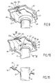
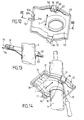
- another strut comprises a shock absorber body A, a lower cup 52, an element 53 secured to the shock absorber body A and elastic indexing means between the element 53 and the lower cup 52 having a lower seat of a helical spring mounted prestressed and not shown.
- the lower cup 52 carries a tongue 54 articulated elastically on the lower cup 52; while the element 53 carries notches 55 a , 55 b , 55 c capable of receiving the indexing tongue 54.
- the contour of the element 53 is inscribed inside the contour of the raised edges of the lower cup 52, a freedom of translation along the arrow T being provided to allow movement from one to the other. of a selected immobilization position corresponding to the indexing by one of the notches 55 a to 55 c of the elastic tongue 54.
- Spaced support conformations 56, 57 are advantageously provided, on the lower cup 52 and on the element 53, to facilitate relative displacement in translation in the direction of the arrow T after having released the snap-in tongue 54 from the notch where it was locked: this release position corresponds to the position shown in dotted lines in Figure 13.
- Reinforcement ribs can be provided in the element 53 to resist the thrust of the pre-stressed coil spring no represented.
- the adjustment method according to the invention involves having made an element integral with a body shock absorber and having applied a cup to said element lower spring subjected to coil spring thrust prestressed.
- the strut adjustment is then carried out to index the lower cup in translation in a chosen position, while maintaining the spring prestressed during indexing.
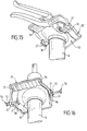
- a mechanical multiplier is used by force.
- a clamp is used as a closing lever.
- the tongs of the pliers act on the opposite external faces of a extension 37 and a tab 36 for moving a lower cup 32 relative to an element 33 integral with a shock absorber body A. This displacement thus makes it possible to blow up undulations 34 of element 33 by cooperating undulations 35 of a cup lower 32 to a selected position corresponding to the setting sought from the axis of the coil spring with respect to the axis of shock absorber A.
- another alternative embodiment of the invention comprises screwing means 70 to 72 to allow a precise adjustment of a lower cup 32 relative to an element 33 integral with a shock absorber body A.
- At least one screw 70 is mounted on at least one extension 37 to act and repel a tab 36 at the means of the support end 71 of the screw 70.
- a screw 70 is used whose end 71 provides fine adjustment, with position locking by means of a lock nut 72 to block mechanical mounting in one position chosen asset.
- the screws 70 protrude from the lower cup 32; however, the invention also allows to consider the variant according to which the screws 70 do not protrude from the lower cup 32, but are on the contrary mounted on legs 36 to be screwed in and out from the inside, using the extensions 37 inside the U-shape.
- the damper body instead of making an independent element and then secure to the damper body, provision may be made for shape of the damper body to form the element 3, 23, 33, 43 or 53 by bringing it together with the ferrule of the body damper.
- the body of shock absorber is somehow locally inflated or deformed at the place corresponding to said element.
Landscapes
- Engineering & Computer Science (AREA)
- Mechanical Engineering (AREA)
- Fluid-Damping Devices (AREA)
- Vehicle Body Suspensions (AREA)
- Disintegrating Or Milling (AREA)
- Body Structure For Vehicles (AREA)
- Control Of Motors That Do Not Use Commutators (AREA)
Description
- la figure 1 représente schématiquement une vue en perspective partielle éclatée dans le sens de la flèche I de la figure 2 d'un premier mode de réalisation de l'invention ;
- la figure 2 représente schématiquement une vue en perspective partielle éclatée dans le sens de la flèche II de la figure 1 d'un premier mode de réalisation de l'invention ;
- la figure 3 représente schématiquement une vue en perspective partielle assemblée dans le sens de la flèche III de la figure 4 d'un deuxième mode de réalisation de l'invention ;
- la figure 4 représente schématiquement une vue en coupe selon la ligne IV-IV de la figure 3 du deuxième mode de réalisation de l'invention ;
- la figure 5 représente schématiquement une vue en perspective éclatée d'un troisième mode de réalisation de l'invention ;
- les figures 6 et 7 représentent schématiquement des vues en section partielle selon les lignes VI-VI et VII-VII de la figure 5 du troisième mode de réalisation de l'invention dans deux positions d'indexation différentes ;
- la figure 8 représente schématiquement une vue en perspective partielle éclatée d'un quatrième mode de réalisation de l'invention ;
- la figure 9 représente schématiquement une vue en perspective partielle éclatée d'un cinquième mode de réalisation de l'invention ;
- la figure 10 représente schématiquement une vue partielle en perspective assemblée du mode de réalisation de la figure 9 ;
- la figure 11 représente schématiquement une vue en section selon la ligne IX-IX de la figure 10 ;
- la figure 12 représente schématiquement une vue partielle en perspective assemblée d'un sixième mode de réalisation de l'invention ;
- la figure 13 représente schématiquement une vue en section selon la ligne XIII-XIII de la figure 12 du sixième mode de réalisation de l'invention ;
- les figures 14 à 16 illustrent des variantes d'une étape de procédé de réglage selon l'invention.
Claims (10)
- Jambe de force d'une suspension de roue de type Mac Pherson, comportant un amortisseur (A) avec un corps et une tige ; ladite tige étant entourée par un ressort hélicoïdal ; ledit ressort hélicoïdal étant monté précontraint entre un siège inférieur (1, 21, 41, 51) d'une coupelle inférieure (2, 22, 32, 42, 52) et un siège supérieur d'une coupelle supérieure traversée par la tige d'amortisseur ; ledit corps d'amortisseur (A) étant destiné à être monté solidaire d'un porte-moyeu définissant un axe de rotation de la roue, la coupelle inférieure (2, 22, 32, 42, 52) étant montée sur un élément porte-coupelle (3, 23, 33, 43, 53) solidaire du corps d'amortisseur et formant une glissière apte à garder ladite coupelle inférieure en translation (T) dans un plan coupant l'axe de l'amortisseur (A), la jambe comportant des moyens de fixation pour immobiliser la coupelle inférieure par rapport à l'élément porte-coupelle en une position choisie parmi plusieurs positions relatives possibles et les moyens de fixation (4, 9 ; 24, 25 ; 34, 35) sont configurés de façon que ladite coupelle inférieure (2, 22, 32, 42, 52) est déplaçable en translation (T) d'une position relative à une autre position relative en exerçant sur ladite coupelle inférieure une poussée dans un sens parallèle à la direction de translation (T) en prenant appui sur ledit élément porte-coupelle (3, 23, 33, 43, 53), tout en maintenant ledit ressort précontraint entre les coupelles caractérisée par le fait que les moyens de fixation comprennent des moyens d'indexation.
- Jambe de force selon la revendication 1, caractérisée par le fait que la jambe de force comporte des moyens mécaniques de fixation, par exemple du genre : vis (5), boulon (6), goupille (7), rivet (8) ou analogue.
- Jambe de force selon la revendication 1 ou la revendication 2, caractérisée par le fait que lesdits moyens d'indexation (4, 9) en translation (T) comprennent au moins une pluralité de premiers orifices (4) aptes à être mis en correspondance avec au moins un autre second orifice (9).
- Jambe de force selon la revendication 1, caractérisée par le fait que les moyens d'indexation en translation comprennent au moins une pluralité de premières conformations (24, 34) aptes à coopérer avec au moins une seconde conformation (25, 35).
- Jambe de force selon la revendication 1, caractérisée par le fait que les moyens (44, 45 ; 54, 55) d'indexation en translation (T) comprennent une languette (44, 54) élastique d'encliquetage et au moins une encoche (45, 55) d'indexation apte à coopérer avec ladite languette élastique (44, 54).
- Jambe de force selon la revendication 5, caractérisée par le fait que l'élément porte-coupelle (43) solidaire du corps (A) d'amortisseur comporte une conformation élastique mâle (44) et la coupelle inférieure (42) comporte une conformation femelle (45) apte à être indexée par ladite conformation élastique mâle (44).
- Jambe de force selon l'une quelconque des revendications précédentes, caractérisée par le fait que l'élément porte-coupelle (43, 53) solidaire du corps (A) d'amortisseur et la coupelle inférieure (42, 52) portent des conformations d'appui (46, 47 ; 56, 57) espacées pour le réglage dans la position choisie d'immobilisation de la coupelle inférieure (42, 52) par rapport audit élément porte-coupelle (43, 53).
- Jambe de force selon la revendication 7, caractérisée par le fait que les conformations d'appui espacées (46, 56 ou 47, 57) portent des moyens de réglage par vissage (70-72).
- Procédé de réglage d'une jambe de force de suspension Mac Pherson ; ladite jambe de force comportant un amortisseur (A) avec un corps et une tige ; ladite tige étant entourée par un ressort hélicoïdal ; ledit ressort hélicoïdal étant monté précontraint entre un siège inférieur (1, 21, 41, 51) d'une coupelle inférieure (2, 22, 32, 42, 52) et un siège supérieur d'une coupelle supérieure traversée par la tige d'amortisseur ; ledit corps d'amortisseur (A) étant destiné à être monté solidaire d'un porte-moyeu définissant un axe de rotation de la roue, la coupelle inférieure (2, 22, 32, 42, 52) étant montée sur un élément porte-coupelle (3, 23, 33, 43, 53) solidaire du corps d'amortisseur et formant une glissière apte à guider ladite coupelle inférieure en translation (T) dans un plan coupant l'axe de l'amortisseur (A), la jambe comportant des moyens d'indexation pour immobiliser la coupelle inférieure par rapport à l'élément porte-coupelle en une position choisie parmi plusieurs positions relatives possibles ; ledit procédé comportant l'étape suivante : exercer une poussée sur la coupelle inférieure (2, 22, 32, 42, 52) dans un sens parallèle à la direction de translation (T) en prenant appui sur l' élément porte-coupelle (3, 23, 33, 43, 53) pour déplacer la coupelle (2, 22, 32, 42, 52) par rapport à l'élément porte-coupelle (3, 23, 33, 43, 53) d'une position indexée à une autre position tout en maintenant le ressort précontraint entre les coupelles.
- Procédé selon la revendication 9, dans lequel on dégage des moyens élastiques (44, 54) d'encliquetage relatif entre la coupelle inférieure (2, 22, 32, 42, 52) et l'élément porte-coupelle (3, 23, 33, 43, 53), avant d'exercer ladite poussée sur la coupelle inférieure (2, 22, 32, 42, 52) en vue de la déplacer.
Applications Claiming Priority (3)
| Application Number | Priority Date | Filing Date | Title |
|---|---|---|---|
| FR9903426A FR2791608A1 (fr) | 1999-03-19 | 1999-03-19 | Jambe de force de suspension mac pherson et procede de reglage correspondant |
| FR9903426 | 1999-03-19 | ||
| PCT/FR2000/000301 WO2000056560A1 (fr) | 1999-03-19 | 2000-02-09 | Jambe de force de suspension mac pherson et procede de reglage correspondant |
Publications (2)
| Publication Number | Publication Date |
|---|---|
| EP1077820A1 EP1077820A1 (fr) | 2001-02-28 |
| EP1077820B1 true EP1077820B1 (fr) | 2003-05-28 |
Family
ID=9543394
Family Applications (1)
| Application Number | Title | Priority Date | Filing Date |
|---|---|---|---|
| EP00903757A Expired - Lifetime EP1077820B1 (fr) | 1999-03-19 | 2000-02-09 | Jambe de force de suspension mac pherson et procede de reglage correspondant |
Country Status (6)
| Country | Link |
|---|---|
| EP (1) | EP1077820B1 (fr) |
| JP (1) | JP2002540352A (fr) |
| AT (1) | ATE241484T1 (fr) |
| DE (1) | DE60002960T2 (fr) |
| FR (1) | FR2791608A1 (fr) |
| WO (1) | WO2000056560A1 (fr) |
Families Citing this family (6)
| Publication number | Priority date | Publication date | Assignee | Title |
|---|---|---|---|---|
| DE10053576C1 (de) * | 2000-10-28 | 2002-03-21 | Mannesmann Sachs Ag | Federbein mit einstellbarem Federteller |
| FR2825126B1 (fr) * | 2001-05-22 | 2004-02-20 | Allevard Rejna Technologie Fro | Systeme anti-rotation et anti-migration d'un ressort sur ses appuis |
| JP4538428B2 (ja) | 2005-07-05 | 2010-09-08 | トヨタ自動車株式会社 | ショックアブソーバ用スプリングシート及びフューエルインレットパイプの配置構造 |
| JP5909384B2 (ja) * | 2012-02-29 | 2016-04-26 | Kyb株式会社 | 緩衝器 |
| JP5871380B2 (ja) * | 2012-02-29 | 2016-03-01 | Kyb株式会社 | 緩衝器 |
| DE102019208170A1 (de) * | 2019-06-05 | 2020-12-10 | Aktiebolaget Skf | Aufhängungsaxiallagervorrichtung und ein mit einer solchen Vorrichtung ausgerüstetes Federbein |
Family Cites Families (5)
| Publication number | Priority date | Publication date | Assignee | Title |
|---|---|---|---|---|
| US3717354A (en) * | 1971-08-26 | 1973-02-20 | Gen Motors Corp | Vehicle suspension system |
| US4366969A (en) * | 1981-07-21 | 1983-01-04 | Moog Automotive, Inc. | Adjustable leveling suspension unit for vehicles |
| US4581802A (en) * | 1985-02-22 | 1986-04-15 | Castoe John H | Caster adjustment tool |
| EP0780250B1 (fr) | 1995-12-19 | 2003-04-02 | COMPAGNIE GENERALE DES ETABLISSEMENTS MICHELIN-MICHELIN & CIE | Réglage précis d'une jambe de force de suspension MacPherson: moyens de réglage sur la jambe et banc de mesure |
| JPH11129721A (ja) * | 1997-10-31 | 1999-05-18 | Chuo Spring Co Ltd | 車両懸架装置 |
-
1999
- 1999-03-19 FR FR9903426A patent/FR2791608A1/fr active Pending
-
2000
- 2000-02-09 WO PCT/FR2000/000301 patent/WO2000056560A1/fr not_active Ceased
- 2000-02-09 JP JP2000606437A patent/JP2002540352A/ja active Pending
- 2000-02-09 EP EP00903757A patent/EP1077820B1/fr not_active Expired - Lifetime
- 2000-02-09 AT AT00903757T patent/ATE241484T1/de not_active IP Right Cessation
- 2000-02-09 DE DE60002960T patent/DE60002960T2/de not_active Expired - Fee Related
Also Published As
| Publication number | Publication date |
|---|---|
| WO2000056560A1 (fr) | 2000-09-28 |
| DE60002960D1 (de) | 2003-07-03 |
| JP2002540352A (ja) | 2002-11-26 |
| FR2791608A1 (fr) | 2000-10-06 |
| EP1077820A1 (fr) | 2001-02-28 |
| ATE241484T1 (de) | 2003-06-15 |
| DE60002960T2 (de) | 2004-02-19 |
Similar Documents
| Publication | Publication Date | Title |
|---|---|---|
| EP1213980B1 (fr) | Dispositif de verrouillage d'une position d'une piece mobile par rapport a une piece fixe | |
| FR2817596A1 (fr) | Systeme d'assemblage au moyen d'un dispositif d'ancrage a billes | |
| EP3546685A1 (fr) | Dispositif d'ajustement de l'elevation d'une piece | |
| WO2004106799A2 (fr) | Embout de connexion rapide | |
| EP0919679A1 (fr) | Verrou à encliquetage destiné notamment à la fixation d'un siège pour véhicule sur un plancher de ce véhicule | |
| EP0750087A1 (fr) | Verrou perfectionné destiné notamment à la fixation d'un siège pour véhicule automobile sur un plancher de ce véhicule | |
| EP1077820A1 (fr) | Jambe de force de suspension mac pherson et procede de reglage correspondant | |
| FR2557776A1 (fr) | Chaussure de ski a amortisseur. | |
| EP0352162A1 (fr) | Système de changement rapide de mors de serrage sur une machine-outil | |
| CH697152A5 (fr) | Dispositif de fixation d'une extrémité d'un lien à un objet, notamment une montre. | |
| EP4073394A1 (fr) | Dispositif d'assemblage amovible entre deux pièces | |
| FR2786520A1 (fr) | Verrou et agencement de ce verrou dans un support | |
| EP3682991B1 (fr) | Bague et douille de serrage a expansion radiale | |
| EP0936128B1 (fr) | Système de direction, volant et colonne convenant à ce système | |
| FR2747437A1 (fr) | Embout verrouillable pour element d'accouplement | |
| EP0948303B1 (fr) | Dispositif de blocage | |
| FR3084625A1 (fr) | Systeme de fixation d'un siege et aeronef associe | |
| WO2005095015A1 (fr) | Outil de sertissage et appareil de sertissage pourvu d'un tel outil | |
| FR2697874A1 (fr) | Dispositif de liaison d'un élément longiligne et d'un support de cet élément. | |
| FR2733609A1 (fr) | Mecanisme de retenue de levier de commande | |
| EP3342687A1 (fr) | Pièce de carrosserie comportant une ouverture apte à recevoir une trappe | |
| FR2793199A1 (fr) | Ensemble de verrou destine notamment a la fixation d'un siege pour vehicule automobile sur un plancher de ce vehicule et piece pour cet ensemble | |
| EP0687819B1 (fr) | Dispositif d'assemblage d'au moins deux éléments par exemple de carrosserie automobile | |
| EP4123187B1 (fr) | Fixation pour l'assemblage temporaire de structures | |
| FR2771147A1 (fr) | Frein a disque a etrier flottant a une seule colonnette |
Legal Events
| Date | Code | Title | Description |
|---|---|---|---|
| PUAI | Public reference made under article 153(3) epc to a published international application that has entered the european phase |
Free format text: ORIGINAL CODE: 0009012 |
|
| 17P | Request for examination filed |
Effective date: 20001114 |
|
| AK | Designated contracting states |
Kind code of ref document: A1 Designated state(s): AT BE CH CY DE DK ES FI FR GB GR IE IT LI LU MC NL PT SE |
|
| RIN1 | Information on inventor provided before grant (corrected) |
Inventor name: AUBAREDE, FRANCIS Inventor name: DUCLOUX, ANTOINE |
|
| 17Q | First examination report despatched |
Effective date: 20020726 |
|
| GRAH | Despatch of communication of intention to grant a patent |
Free format text: ORIGINAL CODE: EPIDOS IGRA |
|
| GRAH | Despatch of communication of intention to grant a patent |
Free format text: ORIGINAL CODE: EPIDOS IGRA |
|
| GRAA | (expected) grant |
Free format text: ORIGINAL CODE: 0009210 |
|
| AK | Designated contracting states |
Designated state(s): AT BE CH CY DE DK ES FI FR GB GR IE IT LI LU MC NL PT SE |
|
| PG25 | Lapsed in a contracting state [announced via postgrant information from national office to epo] |
Ref country code: IE Free format text: LAPSE BECAUSE OF FAILURE TO SUBMIT A TRANSLATION OF THE DESCRIPTION OR TO PAY THE FEE WITHIN THE PRESCRIBED TIME-LIMIT Effective date: 20030528 Ref country code: FI Free format text: LAPSE BECAUSE OF FAILURE TO SUBMIT A TRANSLATION OF THE DESCRIPTION OR TO PAY THE FEE WITHIN THE PRESCRIBED TIME-LIMIT Effective date: 20030528 Ref country code: IT Free format text: LAPSE BECAUSE OF FAILURE TO SUBMIT A TRANSLATION OF THE DESCRIPTION OR TO PAY THE FEE WITHIN THE PRESCRIBED TIME-LIMIT;WARNING: LAPSES OF ITALIAN PATENTS WITH EFFECTIVE DATE BEFORE 2007 MAY HAVE OCCURRED AT ANY TIME BEFORE 2007. THE CORRECT EFFECTIVE DATE MAY BE DIFFERENT FROM THE ONE RECORDED. Effective date: 20030528 Ref country code: CY Free format text: LAPSE BECAUSE OF FAILURE TO SUBMIT A TRANSLATION OF THE DESCRIPTION OR TO PAY THE FEE WITHIN THE PRESCRIBED TIME-LIMIT Effective date: 20030528 Ref country code: AT Free format text: LAPSE BECAUSE OF FAILURE TO SUBMIT A TRANSLATION OF THE DESCRIPTION OR TO PAY THE FEE WITHIN THE PRESCRIBED TIME-LIMIT Effective date: 20030528 Ref country code: NL Free format text: LAPSE BECAUSE OF FAILURE TO SUBMIT A TRANSLATION OF THE DESCRIPTION OR TO PAY THE FEE WITHIN THE PRESCRIBED TIME-LIMIT Effective date: 20030528 |
|
| REG | Reference to a national code |
Ref country code: GB Ref legal event code: FG4D Free format text: NOT ENGLISH |
|
| REG | Reference to a national code |
Ref country code: CH Ref legal event code: EP |
|
| REG | Reference to a national code |
Ref country code: IE Ref legal event code: FG4D Free format text: FRENCH |
|
| REF | Corresponds to: |
Ref document number: 60002960 Country of ref document: DE Date of ref document: 20030703 Kind code of ref document: P |
|
| PG25 | Lapsed in a contracting state [announced via postgrant information from national office to epo] |
Ref country code: SE Free format text: LAPSE BECAUSE OF FAILURE TO SUBMIT A TRANSLATION OF THE DESCRIPTION OR TO PAY THE FEE WITHIN THE PRESCRIBED TIME-LIMIT Effective date: 20030828 Ref country code: PT Free format text: LAPSE BECAUSE OF FAILURE TO SUBMIT A TRANSLATION OF THE DESCRIPTION OR TO PAY THE FEE WITHIN THE PRESCRIBED TIME-LIMIT Effective date: 20030828 Ref country code: GR Free format text: LAPSE BECAUSE OF FAILURE TO SUBMIT A TRANSLATION OF THE DESCRIPTION OR TO PAY THE FEE WITHIN THE PRESCRIBED TIME-LIMIT Effective date: 20030828 Ref country code: DK Free format text: LAPSE BECAUSE OF FAILURE TO SUBMIT A TRANSLATION OF THE DESCRIPTION OR TO PAY THE FEE WITHIN THE PRESCRIBED TIME-LIMIT Effective date: 20030828 |
|
| PG25 | Lapsed in a contracting state [announced via postgrant information from national office to epo] |
Ref country code: ES Free format text: LAPSE BECAUSE OF FAILURE TO SUBMIT A TRANSLATION OF THE DESCRIPTION OR TO PAY THE FEE WITHIN THE PRESCRIBED TIME-LIMIT Effective date: 20030908 |
|
| GBT | Gb: translation of ep patent filed (gb section 77(6)(a)/1977) | ||
| NLV1 | Nl: lapsed or annulled due to failure to fulfill the requirements of art. 29p and 29m of the patents act | ||
| REG | Reference to a national code |
Ref country code: IE Ref legal event code: FD4D |
|
| PG25 | Lapsed in a contracting state [announced via postgrant information from national office to epo] |
Ref country code: LU Free format text: LAPSE BECAUSE OF NON-PAYMENT OF DUE FEES Effective date: 20040209 |
|
| PG25 | Lapsed in a contracting state [announced via postgrant information from national office to epo] |
Ref country code: MC Free format text: LAPSE BECAUSE OF NON-PAYMENT OF DUE FEES Effective date: 20040228 Ref country code: BE Free format text: LAPSE BECAUSE OF NON-PAYMENT OF DUE FEES Effective date: 20040228 |
|
| PG25 | Lapsed in a contracting state [announced via postgrant information from national office to epo] |
Ref country code: CH Free format text: LAPSE BECAUSE OF NON-PAYMENT OF DUE FEES Effective date: 20040229 Ref country code: LI Free format text: LAPSE BECAUSE OF NON-PAYMENT OF DUE FEES Effective date: 20040229 |
|
| PLBE | No opposition filed within time limit |
Free format text: ORIGINAL CODE: 0009261 |
|
| STAA | Information on the status of an ep patent application or granted ep patent |
Free format text: STATUS: NO OPPOSITION FILED WITHIN TIME LIMIT |
|
| 26N | No opposition filed |
Effective date: 20040302 |
|
| BERE | Be: lapsed |
Owner name: CIE GENERALE DES ETS *MICHELIN-MICHELIN & CIE Effective date: 20040228 |
|
| REG | Reference to a national code |
Ref country code: CH Ref legal event code: PL |
|
| PGFP | Annual fee paid to national office [announced via postgrant information from national office to epo] |
Ref country code: DE Payment date: 20080219 Year of fee payment: 9 Ref country code: GB Payment date: 20080220 Year of fee payment: 9 |
|
| PGFP | Annual fee paid to national office [announced via postgrant information from national office to epo] |
Ref country code: FR Payment date: 20080214 Year of fee payment: 9 |
|
| GBPC | Gb: european patent ceased through non-payment of renewal fee |
Effective date: 20090209 |
|
| REG | Reference to a national code |
Ref country code: FR Ref legal event code: ST Effective date: 20091030 |
|
| PG25 | Lapsed in a contracting state [announced via postgrant information from national office to epo] |
Ref country code: DE Free format text: LAPSE BECAUSE OF NON-PAYMENT OF DUE FEES Effective date: 20090901 |
|
| PG25 | Lapsed in a contracting state [announced via postgrant information from national office to epo] |
Ref country code: FR Free format text: LAPSE BECAUSE OF NON-PAYMENT OF DUE FEES Effective date: 20090302 Ref country code: GB Free format text: LAPSE BECAUSE OF NON-PAYMENT OF DUE FEES Effective date: 20090209 |