EP1077810B1 - Side-lay for a sheet-fed machine - Google Patents
Side-lay for a sheet-fed machine Download PDFInfo
- Publication number
- EP1077810B1 EP1077810B1 EP99915865A EP99915865A EP1077810B1 EP 1077810 B1 EP1077810 B1 EP 1077810B1 EP 99915865 A EP99915865 A EP 99915865A EP 99915865 A EP99915865 A EP 99915865A EP 1077810 B1 EP1077810 B1 EP 1077810B1
- Authority
- EP
- European Patent Office
- Prior art keywords
- sheet
- lay
- sheets
- lays
- carriage
- Prior art date
- Legal status (The legal status is an assumption and is not a legal conclusion. Google has not performed a legal analysis and makes no representation as to the accuracy of the status listed.)
- Expired - Lifetime
Links
- 230000004048 modification Effects 0.000 description 8
- 238000012986 modification Methods 0.000 description 8
- 238000004080 punching Methods 0.000 description 3
- 239000011295 pitch Substances 0.000 description 2
- 239000003086 colorant Substances 0.000 description 1
- 238000010276 construction Methods 0.000 description 1
- 239000002783 friction material Substances 0.000 description 1
- 238000004519 manufacturing process Methods 0.000 description 1
- 239000000463 material Substances 0.000 description 1
- 230000002093 peripheral effect Effects 0.000 description 1
Images

Classifications
-
- B—PERFORMING OPERATIONS; TRANSPORTING
- B65—CONVEYING; PACKING; STORING; HANDLING THIN OR FILAMENTARY MATERIAL
- B65H—HANDLING THIN OR FILAMENTARY MATERIAL, e.g. SHEETS, WEBS, CABLES
- B65H9/00—Registering, e.g. orientating, articles; Devices therefor
- B65H9/10—Pusher and like movable registers; Pusher or gripper devices which move articles into registered position
- B65H9/101—Pusher and like movable registers; Pusher or gripper devices which move articles into registered position acting on the edge of the article
-
- B—PERFORMING OPERATIONS; TRANSPORTING
- B65—CONVEYING; PACKING; STORING; HANDLING THIN OR FILAMENTARY MATERIAL
- B65H—HANDLING THIN OR FILAMENTARY MATERIAL, e.g. SHEETS, WEBS, CABLES
- B65H2402/00—Constructional details of the handling apparatus
- B65H2402/30—Supports; Subassemblies; Mountings thereof
- B65H2402/31—Pivoting support means
-
- B—PERFORMING OPERATIONS; TRANSPORTING
- B65—CONVEYING; PACKING; STORING; HANDLING THIN OR FILAMENTARY MATERIAL
- B65H—HANDLING THIN OR FILAMENTARY MATERIAL, e.g. SHEETS, WEBS, CABLES
- B65H2701/00—Handled material; Storage means
- B65H2701/10—Handled articles or webs
- B65H2701/19—Specific article or web
- B65H2701/1912—Banknotes, bills and cheques or the like
Definitions
- This invention relates to sheet-fed machines such as printing machines and punching machines and more particularly to side-lays therefor.
- Machines for printing different colours on sheets transferred to successive stations including respective impression cylinders must register each sheet with great precision at each station to ensure printing accuracy.
- punching machines must stationarily register pre-printed sheets with the same precision to ensure punching accuracy.
- the sheets are often not precisely rectangular, for instance out-of-square or tapered, and front lays carried by each impression cylinder of a printing machine for the precise registration of their leading edges have to be adjusted before production printing can commence.
- side lays for the registration of their side edges comprise one so-called fixed side-lay secured on a carriage reciprocable out of and into a predetermined registration position, as each sheet travels into printing position, by power-operated means along guides fixed to the machine frame, and another side-lay at the opposite side of the sheet reciprocable in like manner out of and into a predetermined position but in addition acted upon resiliently by spring or pneumatic means so that when in said position it urges the sheet into contact with said one side-lay.
- the side-lays normally comprise single rollers when so-called body-plate, which has nominally straight sides, is being printed. However, printing is also regularly effected on so-called scroll-edge sheets which have castellated sides.
- the castellations on one side may be offset by half a pitch from the castellations on the other side, and different pitches of castellations may be employed.
- side-lays which are elongated strictly in the direction of travel of the sheets, and which typically incorporate a straight line of small ball bearings, have been employed.
- US-A-2528106 discloses a pair of side-lays for a printing press each of which comprises a slightly arcuate array of rollers carried by an arm pivotted at one end and positively swung about said end by reciprocating its other end towards and away from the centre of the press.
- the rollers are on a bar yieldably coupled to the arm and urged towards the centre of the press by a spring.
- DE-A-19534966 discloses a pair of side-lays for a banknote delivery apparatus each of which is pivotted at one end, spring-loaded towards the centre of the apparatus, and released by a latch to allow the spring to operate.
- DE-A-4426861 discloses a side-lay for a sheet delivery apparatus which consists of a single roller or a pair of rollers mounted at one end of an articulated spring-loaded arm which is positively rotated about its other end.
- US-A-4838538 discloses elongated side-lays for a sheet material positioning apparatus which are pivotably mounted between their ends but locked in predetermined angularly adjusted positions by bolts.
- the object of the present invention is to overcome all of the aforesaid disadvantages.
- a side-lay for a sheet-fed machine, comprising a member incorporating sheet side support means which are elongated generally in the direction of travel of the sheets, is characterised in that said member is moveably mounted between its ends so as to enable its support means to make end-to-end contact with skewed sheet sides.
- the member is pivotally mounted.
- pivotal movement of the member is limited by means of stops.
- the stops may be adjustable.
- the member may be centred or angularly biased by adjustable spring means.
- the member is compliantly mounted.
- the member is both pivotally and compliantly mounted.
- Movement of the member may be damped.
- the support means comprise a straight line of bearings.
- the member is mounted on a carriage reciprocable by power-operated means along fixed guides at right angles to the direction of travel of the sheets.
- the sheets are pulled, pushed or guided into contact therewith.
- FIG. 1 the leading edge 10 of a scroll-edge sheet 12 travelling through a printing machine in the direction indicated by the arrow 14 is precisely registered at each impression cylinder on the machine by two front lays 16 which are adjustable as shown by the arrows 18.
- the sheet 12 is urged into contact with the front lays 16 by springs 20 acting on pushers 22 carried by conventional sheet transfer means (not shown) moving continuously along the machine frame.
- a so-called fixed side-lay indicated generally at 24 comprises a carriage 26 reciprocable by power-operated means (not shown) along guides 28 fixed to the machine frame at right angles to the direction of travel of the sheet 12.
- An elongated member 30 incorporating sheet side support means (not shown) is pivotally mounted on the carriage 26 about a set-screw 32.
- Another side-lay indicated generally at 36 comprises a carriage 26 reciprocable by power-operated means (not shown) along guides 28, a member 30 and a set-screw 32 identical to those of the fixed side-lay 24, but instead of a stop 34 the side-lay 36 is provided with a spring 38 acting on its carriage so that it urges the sheet 12 into contact with the fixed side-lay 24.
- the elongated members 30 span a plurality of the tips 40 of the castellations 42 along the side edges of the sheet 12, and by virtue of the pivotal connection of said members to the carriages 26 their sheet side support means make end-to-end contact with said tips even though the sheet sides may have been skewed relative to the direction of travel 14 of the sheet 12 by necessary adjustment of the front lays 16.
- the load is accordingly spread evenly along each side-lay, and the net reaction is always through the axis of its set-screw 32. Thus over-constraint and consequent misalignment due to sheets not being precisely rectangular is avoided.
- the guides 28 comprise a rail which is V-shaped along each edge so as to be engageable between two pairs of rollers 44 with v-shaped peripheral grooves which are rotateably mounted on the carriage 26.
- the member 30 comprises a body 46 to which there are rigidly secured elongated upper and lower plates 48 with a space between them in which there are rotateably confined a straight line of small ball bearings 50 constituting support means which facilitate sliding of each sheet side through said space as the sheet travels along the machine.
- the body 46 is pivotally mounted on the carriage 26 about the set-screw 32 as previously stated, and pivotal movement of the member 30 is limited at each of its ends by means of adjustable stops comprising two set-screws 52 on the carriage 26 which co-act with opposite sides of a tongue 54 formed integrally on the body 46.
- Spring means comprising two leaf-springs 56 anchored on the carriage 26 can if required be adjustably moved by respective set-screws 58 on the carriage into contact with the tongue 54 so as to centre or angularly bias the member 30 relative to the body 46.
- a predetermined registration position of the fixed side-lay 24 is defined by the adjustable stop means indicated generally at 34 which limit movement of the carriage 26 along the guides 28 in the direction towards each sheet.
- each side-lay is compliantly mounted on its carriage, for example by means of a rubber block or a leaf spring, instead of being pivotally mounted thereon.
- each side-lay is both pivotally and compliantly mounted on its carriage.
- the adjustable leaf-springs for centring or angularly biasing each side-lay on its carriage are omitted.
- the straight line of small ball bearings is replaced by a linear bearing or by a straight strip of low-friction material.
- the stops which co-act with the tongue are fixed.
- movement of the member is damped e.g. by friction.
- the member is mounted on means other than a reciprocable carriage, for example on an arcuately-moveable member or on means permanently fixed to the machine frame.
Landscapes
- Registering Or Overturning Sheets (AREA)
Abstract
Description
- This invention relates to sheet-fed machines such as printing machines and punching machines and more particularly to side-lays therefor.
- Machines for printing different colours on sheets transferred to successive stations including respective impression cylinders must register each sheet with great precision at each station to ensure printing accuracy. Similarly, punching machines must stationarily register pre-printed sheets with the same precision to ensure punching accuracy. The sheets are often not precisely rectangular, for instance out-of-square or tapered, and front lays carried by each impression cylinder of a printing machine for the precise registration of their leading edges have to be adjusted before production printing can commence. In one known arrangement, side lays for the registration of their side edges comprise one so-called fixed side-lay secured on a carriage reciprocable out of and into a predetermined registration position, as each sheet travels into printing position, by power-operated means along guides fixed to the machine frame, and another side-lay at the opposite side of the sheet reciprocable in like manner out of and into a predetermined position but in addition acted upon resiliently by spring or pneumatic means so that when in said position it urges the sheet into contact with said one side-lay. The side-lays normally comprise single rollers when so-called body-plate, which has nominally straight sides, is being printed. However, printing is also regularly effected on so-called scroll-edge sheets which have castellated sides. The castellations on one side may be offset by half a pitch from the castellations on the other side, and different pitches of castellations may be employed. In order to register the side edges of scroll-edge sheets, side-lays which are elongated strictly in the direction of travel of the sheets, and which typically incorporate a straight line of small ball bearings, have been employed. However, when necessary adjustment of the front lays has resulted in skewing of the side edges of the sheets relative to said direction, these elongated side-lays have the disadvantage that they have not contacted the tips of the castellations along the full length of the side-lays, so that the sheets have been over-constrained by the combined action of the front lays and side-lays and thus misalignment of the sheets has occurred but not been satisfactorily accommodated to the detriment of printing accuracy.
- In another known arrangement using elongated side-lays, the angular disposition of these is set by manual adjustment so as to exactly match any skewing of the side edges of a sheet due to necessary adjustment of the front lays, but this arrangement has the disadvantages that misalignment of out-of-square or tapered sheets cannot be avoided, and that extensive time is required to make the manual adjustment.
- US-A-2528106 discloses a pair of side-lays for a printing press each of which comprises a slightly arcuate array of rollers carried by an arm pivotted at one end and positively swung about said end by reciprocating its other end towards and away from the centre of the press. In one of the side-lays the rollers are on a bar yieldably coupled to the arm and urged towards the centre of the press by a spring.
- DE-A-19534966 discloses a pair of side-lays for a banknote delivery apparatus each of which is pivotted at one end, spring-loaded towards the centre of the apparatus, and released by a latch to allow the spring to operate.
- DE-A-4426861 discloses a side-lay for a sheet delivery apparatus which consists of a single roller or a pair of rollers mounted at one end of an articulated spring-loaded arm which is positively rotated about its other end.
- US-A-4838538 discloses elongated side-lays for a sheet material positioning apparatus which are pivotably mounted between their ends but locked in predetermined angularly adjusted positions by bolts.
- The object of the present invention is to overcome all of the aforesaid disadvantages.
- According to the invention, a side-lay, for a sheet-fed machine, comprising a member incorporating sheet side support means which are elongated generally in the direction of travel of the sheets, is characterised in that said member is moveably mounted between its ends so as to enable its support means to make end-to-end contact with skewed sheet sides.
- Preferably, the member is pivotally mounted.
- Preferably, also, pivotal movement of the member is limited by means of stops.
- The stops may be adjustable.
- The member may be centred or angularly biased by adjustable spring means.
- Alternatively, the member is compliantly mounted.
- Alternatively, the member is both pivotally and compliantly mounted.
- Movement of the member may be damped.
- Preferably, the support means comprise a straight line of bearings.
- Preferably, also, the member is mounted on a carriage reciprocable by power-operated means along fixed guides at right angles to the direction of travel of the sheets.
- Preferably, where the side-lay has a fixed registration position, the sheets are pulled, pushed or guided into contact therewith.
- A preferred embodiment of the invention will now be described, by way of example, with reference to the accompanying drawings, of which:-
- Figure 1 is a diagrammatic plan view of a sheet registered by front lays and side-lays; and
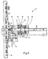
- Figure 2 is a plan view on a larger scale of one of the side-lays.
-
- Referring now to Figure 1, the leading
edge 10 of a scroll-edge sheet 12 travelling through a printing machine in the direction indicated by the arrow 14 is precisely registered at each impression cylinder on the machine by twofront lays 16 which are adjustable as shown by thearrows 18. Thesheet 12 is urged into contact with thefront lays 16 bysprings 20 acting onpushers 22 carried by conventional sheet transfer means (not shown) moving continuously along the machine frame. A so-called fixed side-lay indicated generally at 24 comprises acarriage 26 reciprocable by power-operated means (not shown) alongguides 28 fixed to the machine frame at right angles to the direction of travel of thesheet 12. Anelongated member 30 incorporating sheet side support means (not shown) is pivotally mounted on thecarriage 26 about a set-screw 32. Movement of the fixed side-lay into a predetermined registration position is limited by anadjustable stop 34 secured to theguides 28. Another side-lay indicated generally at 36 comprises acarriage 26 reciprocable by power-operated means (not shown) alongguides 28, amember 30 and a set-screw 32 identical to those of the fixed side-lay 24, but instead of astop 34 the side-lay 36 is provided with aspring 38 acting on its carriage so that it urges thesheet 12 into contact with the fixed side-lay 24. Theelongated members 30 span a plurality of thetips 40 of thecastellations 42 along the side edges of thesheet 12, and by virtue of the pivotal connection of said members to thecarriages 26 their sheet side support means make end-to-end contact with said tips even though the sheet sides may have been skewed relative to the direction of travel 14 of thesheet 12 by necessary adjustment of thefront lays 16. The load is accordingly spread evenly along each side-lay, and the net reaction is always through the axis of its set-screw 32. Thus over-constraint and consequent misalignment due to sheets not being precisely rectangular is avoided. - Referring now to Figure 2, the so-called fixed side-
lay 24 is shown in greater detail. Theguides 28 comprise a rail which is V-shaped along each edge so as to be engageable between two pairs ofrollers 44 with v-shaped peripheral grooves which are rotateably mounted on thecarriage 26. Themember 30 comprises abody 46 to which there are rigidly secured elongated upper andlower plates 48 with a space between them in which there are rotateably confined a straight line ofsmall ball bearings 50 constituting support means which facilitate sliding of each sheet side through said space as the sheet travels along the machine. Thebody 46 is pivotally mounted on thecarriage 26 about the set-screw 32 as previously stated, and pivotal movement of themember 30 is limited at each of its ends by means of adjustable stops comprising two set-screws 52 on thecarriage 26 which co-act with opposite sides of atongue 54 formed integrally on thebody 46. Spring means comprising two leaf-springs 56 anchored on thecarriage 26 can if required be adjustably moved by respective set-screws 58 on the carriage into contact with thetongue 54 so as to centre or angularly bias themember 30 relative to thebody 46. A predetermined registration position of the fixed side-lay 24 is defined by the adjustable stop means indicated generally at 34 which limit movement of thecarriage 26 along theguides 28 in the direction towards each sheet. - The construction, arrangement and operation of the other side-
lay 36 is identical, except that the adjustable stop means 34 are replaced by spring, pneumatic or other resilient means acting on itscarriage 26 to urge each sheet into contact with the fixed side-lay 24 as previously stated. - In a modification, each side-lay is compliantly mounted on its carriage, for example by means of a rubber block or a leaf spring, instead of being pivotally mounted thereon. In another modification, each side-lay is both pivotally and compliantly mounted on its carriage. In a further modification, the adjustable leaf-springs for centring or angularly biasing each side-lay on its carriage are omitted. In yet another modification, the straight line of small ball bearings is replaced by a linear bearing or by a straight strip of low-friction material. In yet a further modification, the stops which co-act with the tongue are fixed. In still another modification, movement of the member is damped e.g. by friction. In still a further modification, the member is mounted on means other than a reciprocable carriage, for example on an arcuately-moveable member or on means permanently fixed to the machine frame.
- In a still further modification, where the side-lay has a fixed registration position, the sheets are pulled, pushed or guided into contact therewith.
- Side-lays according to the invention can also be used with body-plate, with the advantages that the downtime involved in changing over to side-lays of single-roller type is eliminated; and that superior registration is obtained when, as frequently occurs, the side edges of the plates are wavy, in which case said edges are supported at all their high spots.
Claims (11)
- A side-lay (36) for a sheet-fed machine, comprising a member (30) incorporating sheet side support means (50) which are elongated generally in the direction of travel of the sheets, characterised in that said member is moveably mounted between as to enable its support means to make end-to-end contact with skewed sheet sides.
- A side-lay according to claim 1, wherein the member (30) is pivotally mounted.
- A side-lay according to claim 2, wherein pivotal movement of the member (30) is limited by means of stops (52).
- A side-lay according to claim 3, wherein the stops (52) are adjustable.
- A side-lay according to any one of claims 2 to 4, wherein the member (30) is centred or angularly biased by adjustable spring means (56).
- A side-lay according to claim 1, wherein the member (30) is compliantly mounted.
- A side-lay according to claim 1, wherein the member (30) is both pivotally and compliantly mounted.
- A side-lay according to any one of the preceding claims, wherein movement of the member (30) is damped.
- A side-lay according to any one of the preceding claims, wherein the support means (50) comprise a straight line of bearings.
- A side-lay according to any one of the preceding claims, wherein the member (30) is mounted on a carriage (26) reciprocable by power-operated means along fixed guides (28) at right angles to the direction of travel of the sheets.
- A side-lay according to any one of the preceding claims, said side-lay having a fixed registration position and the sheets being pulled, pushed or guided into contact therewith.
Applications Claiming Priority (3)
| Application Number | Priority Date | Filing Date | Title |
|---|---|---|---|
| GB9807863 | 1998-04-15 | ||
| GBGB9807863.7A GB9807863D0 (en) | 1998-04-15 | 1998-04-15 | Sheet-fed machines |
| PCT/GB1999/000962 WO1999052711A1 (en) | 1998-04-15 | 1999-04-14 | Side-lay for a sheet-fed machine |
Publications (2)
| Publication Number | Publication Date |
|---|---|
| EP1077810A1 EP1077810A1 (en) | 2001-02-28 |
| EP1077810B1 true EP1077810B1 (en) | 2003-07-09 |
Family
ID=10830284
Family Applications (1)
| Application Number | Title | Priority Date | Filing Date |
|---|---|---|---|
| EP99915865A Expired - Lifetime EP1077810B1 (en) | 1998-04-15 | 1999-04-14 | Side-lay for a sheet-fed machine |
Country Status (6)
| Country | Link |
|---|---|
| EP (1) | EP1077810B1 (en) |
| JP (1) | JP2002511371A (en) |
| AU (1) | AU3429199A (en) |
| DE (1) | DE69909466D1 (en) |
| GB (2) | GB9807863D0 (en) |
| WO (1) | WO1999052711A1 (en) |
Families Citing this family (7)
| Publication number | Priority date | Publication date | Assignee | Title |
|---|---|---|---|---|
| CN1191943C (en) * | 1998-03-23 | 2005-03-09 | 株式会社理光 | Paper guiding method and apparatus and image forming apparatus |
| JP4963983B2 (en) * | 2007-02-23 | 2012-06-27 | リョービ株式会社 | Transport guide for paper feed unit in sheet-fed printing press |
| US7762547B2 (en) | 2007-09-03 | 2010-07-27 | Universal Entertainment Corporation | Bill processing apparatus |
| CN102922872B (en) * | 2012-10-16 | 2015-01-28 | 山东环球印铁制罐有限公司 | Volute iron printing side mark device |
| EP2759500A1 (en) * | 2013-01-23 | 2014-07-30 | Crabtree Of Gateshead Limited | Locating apparatus for sheet processing apparatus and sheet processing apparatus incorporating such locating apparatus |
| DE102018126049B4 (en) * | 2018-10-19 | 2020-08-27 | Koenig & Bauer Ag | Tabular substrate processing machine with a system, method for setting up and method for operating a system |
| DE102018130149B4 (en) * | 2018-11-28 | 2020-08-27 | Koenig & Bauer Ag | Plant for a sheet-like substrate processing machine and method for operating a plant |
Family Cites Families (11)
| Publication number | Priority date | Publication date | Assignee | Title |
|---|---|---|---|---|
| GB324089A (en) * | 1928-10-15 | 1930-01-15 | Harold Sydney Dix | A rotary intaglio card printing machine |
| DE528991C (en) * | 1929-11-03 | 1931-07-06 | E H Georg Spiess Dr Ing | Device for the lateral alignment of sheets in printing machines o. |
| US2528106A (en) * | 1947-01-09 | 1950-10-31 | Hoe & Co R | Sheet registering mechanism |
| GB624908A (en) * | 1947-04-11 | 1949-06-17 | A H Lakeman Printing Machinery | Improvements in stop cylinder flat bed printing machines |
| DE839644C (en) * | 1950-07-09 | 1952-05-23 | Mabeg Maschinen Bedarf G M B H | Sheet pre-alignment unit on feeding devices for paper processing machines, in particular printing, folding, painting machines, etc. |
| US4228994A (en) * | 1979-07-16 | 1980-10-21 | White Consolidated Industries, Inc. | Variable jogger for a sheet feeder |
| JPH0427879Y2 (en) * | 1986-03-20 | 1992-07-06 | ||
| DE4426861C2 (en) * | 1994-07-29 | 1997-07-17 | Roland Man Druckmasch | Device for the lateral alignment of arcs in an arc stream |
| US5516093A (en) * | 1994-09-06 | 1996-05-14 | Pitney Bowes Inc. | Apparatus method for centering and aligning sheets |
| GB2317881B (en) * | 1994-09-23 | 1998-06-17 | Mars Inc | Method and apparatus for aligning a bank note |
| EP0708046A1 (en) * | 1994-10-21 | 1996-04-24 | Maschinenfabrik Gietz Ag | Register and feeding device |
-
1998
- 1998-04-15 GB GBGB9807863.7A patent/GB9807863D0/en not_active Ceased
-
1999
- 1999-04-14 JP JP2000543300A patent/JP2002511371A/en active Pending
- 1999-04-14 AU AU34291/99A patent/AU3429199A/en not_active Abandoned
- 1999-04-14 DE DE69909466T patent/DE69909466D1/en not_active Expired - Lifetime
- 1999-04-14 EP EP99915865A patent/EP1077810B1/en not_active Expired - Lifetime
- 1999-04-14 WO PCT/GB1999/000962 patent/WO1999052711A1/en active IP Right Grant
- 1999-04-14 GB GB9908383A patent/GB2336358B/en not_active Expired - Fee Related
Also Published As
| Publication number | Publication date |
|---|---|
| JP2002511371A (en) | 2002-04-16 |
| GB9908383D0 (en) | 1999-06-09 |
| DE69909466D1 (en) | 2003-08-14 |
| EP1077810A1 (en) | 2001-02-28 |
| GB2336358A (en) | 1999-10-20 |
| GB9807863D0 (en) | 1998-06-10 |
| WO1999052711A1 (en) | 1999-10-21 |
| GB2336358B (en) | 2002-05-01 |
| AU3429199A (en) | 1999-11-01 |
Similar Documents
| Publication | Publication Date | Title |
|---|---|---|
| US6241242B1 (en) | Deskew of print media | |
| EP0002878A1 (en) | Sheet alignment apparatus | |
| EP1077810B1 (en) | Side-lay for a sheet-fed machine | |
| US4482148A (en) | Variable-width friction-feed paper handling apparatus | |
| US4492135A (en) | Apparatus for handling thin sheets of material | |
| US9315053B2 (en) | Media conveyance device and printing device | |
| JP2008273726A (en) | Folding machine and printer using the same | |
| US20040201168A1 (en) | Device for conveying sheets through a printing machine | |
| KR101275720B1 (en) | Printer Device and Roller Assembly | |
| US5069442A (en) | Transport device for paper sheets of varying or different widths and thickness | |
| US6371480B1 (en) | Device for transporting sheet-like articles | |
| US6293650B1 (en) | In-line printer with manual positionable mechanically interlocked multiple print head assemblies | |
| NL1027003C2 (en) | Printer. | |
| CN104340702B (en) | Tracking in belt on belt architecture through self-alignment | |
| US4630950A (en) | Paper bail for a printer and associated methods of operation thereof | |
| CN106166894B (en) | Plate changer | |
| CN210851718U (en) | Sheet conveying device and line printer | |
| JPH0780327B2 (en) | Paper cutting mechanism in printer | |
| EP0384631B1 (en) | Transport device | |
| EP0915050B1 (en) | A web having alignment indicia and an associated web feeding and working apparatus | |
| US6761676B2 (en) | Device for controlling printed products | |
| EP0143467B1 (en) | Adjusting device for dimensionally adjusting a gap between a platen and a print head assembly and printer using the adjusting device | |
| CN221026558U (en) | Feed end calibrating mechanism | |
| JP6251245B2 (en) | Ink apparatus having adjustment of roller by bending plate and adjustment method | |
| CN109292491B (en) | Automatic deviation rectifying mechanism and method |
Legal Events
| Date | Code | Title | Description |
|---|---|---|---|
| PUAI | Public reference made under article 153(3) epc to a published international application that has entered the european phase |
Free format text: ORIGINAL CODE: 0009012 |
|
| 17P | Request for examination filed |
Effective date: 20001114 |
|
| AK | Designated contracting states |
Kind code of ref document: A1 Designated state(s): BE DE DK ES FR IT NL SE |
|
| 17Q | First examination report despatched |
Effective date: 20010404 |
|
| GRAH | Despatch of communication of intention to grant a patent |
Free format text: ORIGINAL CODE: EPIDOS IGRA |
|
| GRAH | Despatch of communication of intention to grant a patent |
Free format text: ORIGINAL CODE: EPIDOS IGRA |
|
| GRAA | (expected) grant |
Free format text: ORIGINAL CODE: 0009210 |
|
| AK | Designated contracting states |
Designated state(s): BE DE DK ES FR IT NL SE |
|
| PG25 | Lapsed in a contracting state [announced via postgrant information from national office to epo] |
Ref country code: NL Free format text: LAPSE BECAUSE OF FAILURE TO SUBMIT A TRANSLATION OF THE DESCRIPTION OR TO PAY THE FEE WITHIN THE PRESCRIBED TIME-LIMIT Effective date: 20030709 Ref country code: IT Free format text: LAPSE BECAUSE OF FAILURE TO SUBMIT A TRANSLATION OF THE DESCRIPTION OR TO PAY THE FEE WITHIN THE PRESCRIBED TIME-LIMIT;WARNING: LAPSES OF ITALIAN PATENTS WITH EFFECTIVE DATE BEFORE 2007 MAY HAVE OCCURRED AT ANY TIME BEFORE 2007. THE CORRECT EFFECTIVE DATE MAY BE DIFFERENT FROM THE ONE RECORDED. Effective date: 20030709 Ref country code: FR Free format text: LAPSE BECAUSE OF FAILURE TO SUBMIT A TRANSLATION OF THE DESCRIPTION OR TO PAY THE FEE WITHIN THE PRESCRIBED TIME-LIMIT Effective date: 20030709 Ref country code: BE Free format text: LAPSE BECAUSE OF FAILURE TO SUBMIT A TRANSLATION OF THE DESCRIPTION OR TO PAY THE FEE WITHIN THE PRESCRIBED TIME-LIMIT Effective date: 20030709 |
|
| REF | Corresponds to: |
Ref document number: 69909466 Country of ref document: DE Date of ref document: 20030814 Kind code of ref document: P |
|
| PG25 | Lapsed in a contracting state [announced via postgrant information from national office to epo] |
Ref country code: SE Free format text: LAPSE BECAUSE OF FAILURE TO SUBMIT A TRANSLATION OF THE DESCRIPTION OR TO PAY THE FEE WITHIN THE PRESCRIBED TIME-LIMIT Effective date: 20031009 Ref country code: DK Free format text: LAPSE BECAUSE OF FAILURE TO SUBMIT A TRANSLATION OF THE DESCRIPTION OR TO PAY THE FEE WITHIN THE PRESCRIBED TIME-LIMIT Effective date: 20031009 |
|
| PG25 | Lapsed in a contracting state [announced via postgrant information from national office to epo] |
Ref country code: DE Free format text: LAPSE BECAUSE OF FAILURE TO SUBMIT A TRANSLATION OF THE DESCRIPTION OR TO PAY THE FEE WITHIN THE PRESCRIBED TIME-LIMIT Effective date: 20031010 |
|
| PG25 | Lapsed in a contracting state [announced via postgrant information from national office to epo] |
Ref country code: ES Free format text: LAPSE BECAUSE OF FAILURE TO SUBMIT A TRANSLATION OF THE DESCRIPTION OR TO PAY THE FEE WITHIN THE PRESCRIBED TIME-LIMIT Effective date: 20031020 |
|
| NLV1 | Nl: lapsed or annulled due to failure to fulfill the requirements of art. 29p and 29m of the patents act | ||
| PLBE | No opposition filed within time limit |
Free format text: ORIGINAL CODE: 0009261 |
|
| STAA | Information on the status of an ep patent application or granted ep patent |
Free format text: STATUS: NO OPPOSITION FILED WITHIN TIME LIMIT |
|
| 26N | No opposition filed |
Effective date: 20040414 |
|
| EN | Fr: translation not filed |