EP1077176A1 - Bagging and packaging machine capable of sufficiently filling an inert gas into bags - Google Patents
Bagging and packaging machine capable of sufficiently filling an inert gas into bags Download PDFInfo
- Publication number
- EP1077176A1 EP1077176A1 EP00306958A EP00306958A EP1077176A1 EP 1077176 A1 EP1077176 A1 EP 1077176A1 EP 00306958 A EP00306958 A EP 00306958A EP 00306958 A EP00306958 A EP 00306958A EP 1077176 A1 EP1077176 A1 EP 1077176A1
- Authority
- EP
- European Patent Office
- Prior art keywords
- packaging material
- bag
- gas supply
- tube member
- supply passage
- Prior art date
- Legal status (The legal status is an assumption and is not a legal conclusion. Google has not performed a legal analysis and makes no representation as to the accuracy of the status listed.)
- Granted
Links
- 238000004806 packaging method and process Methods 0.000 title claims abstract description 32
- 239000011261 inert gas Substances 0.000 title description 20
- 239000005022 packaging material Substances 0.000 claims abstract description 86
- 238000007789 sealing Methods 0.000 claims description 21
- 238000011144 upstream manufacturing Methods 0.000 claims description 12
- 230000002950 deficient Effects 0.000 abstract description 4
- 238000004519 manufacturing process Methods 0.000 abstract description 4
- 238000009877 rendering Methods 0.000 abstract 1
- 239000007789 gas Substances 0.000 description 71
- 239000000463 material Substances 0.000 description 11
- 230000004927 fusion Effects 0.000 description 6
- XKRFYHLGVUSROY-UHFFFAOYSA-N Argon Chemical compound [Ar] XKRFYHLGVUSROY-UHFFFAOYSA-N 0.000 description 4
- 238000000034 method Methods 0.000 description 4
- IJGRMHOSHXDMSA-UHFFFAOYSA-N Atomic nitrogen Chemical compound N#N IJGRMHOSHXDMSA-UHFFFAOYSA-N 0.000 description 2
- 229910052786 argon Inorganic materials 0.000 description 2
- 229910001873 dinitrogen Inorganic materials 0.000 description 2
- 238000005452 bending Methods 0.000 description 1
- 238000010586 diagram Methods 0.000 description 1
- 230000000694 effects Effects 0.000 description 1
- 230000005484 gravity Effects 0.000 description 1
- 238000012986 modification Methods 0.000 description 1
- 230000004048 modification Effects 0.000 description 1
Images





Classifications
-
- B—PERFORMING OPERATIONS; TRANSPORTING
- B65—CONVEYING; PACKING; STORING; HANDLING THIN OR FILAMENTARY MATERIAL
- B65B—MACHINES, APPARATUS OR DEVICES FOR, OR METHODS OF, PACKAGING ARTICLES OR MATERIALS; UNPACKING
- B65B31/00—Packaging articles or materials under special atmospheric or gaseous conditions; Adding propellants to aerosol containers
- B65B31/04—Evacuating, pressurising or gasifying filled containers or wrappers by means of nozzles through which air or other gas, e.g. an inert gas, is withdrawn or supplied
- B65B31/044—Evacuating, pressurising or gasifying filled containers or wrappers by means of nozzles through which air or other gas, e.g. an inert gas, is withdrawn or supplied the nozzles being combined with a filling device
- B65B31/045—Evacuating, pressurising or gasifying filled containers or wrappers by means of nozzles through which air or other gas, e.g. an inert gas, is withdrawn or supplied the nozzles being combined with a filling device of Vertical Form-Fill-Seal [VFFS] machines
Definitions
- the present invention generally relates to the art of packaging and, more particularly to a bagging and packaging machine for successively forming bags from a strip of bag material and subsequently packaging an article into each of the bags.
- the bagging and packaging machine for successively forming bags from a strip of bag material and subsequently packaging an article into each of the bags undergoes a process of forming the strip of bag material, supplied to a bag former, into a tubular form by means of the bag former by overlapping opposite longitudinal side edges with each other; fusion bonding, by means of a longitudinal sealing unit, the overlapped longitudinal side edges of the tubular strip of bag material in a direction longitudinally thereof at an outer surface of a front wall of an article introducing tube member forming a part of the bag former and, concurrently, fusion bonding the tubular strip of bag material in a direction perpendicular to the longitudinal sense of the tubular strip of bag material to form a bottom seal by means of a transverse sealing unit.
- the machine After an article has been introduced into the tubular strip of bag material through the article introducing tube member, the machine carries out fusion bonding an upper portion of the tubular strip of bag material by means of the transverse sealing unit to form an upper seal to seal the article within the tubular strip of bag material; and finally cutting the tubular strip of bag material along the upper seal to thereby to produce a bagged product containing the article sealed within the bag.
- the gas replacement device disclosed in the above mentioned publication includes, as shown in Fig. 8, a substitute gas supply passage B extending in a vertical direction along an inner surface of the article introducing tube member A, which passage B has a gas inlet B1 defined at an upper end thereof and a gas outlet B2 defined at a lower end thereof.
- An inert gas to be substituted for the air within the bag is supplied into the substitute gas supply passage B through the gas inlet B1 and is discharged through the gas outlet B2 into the bag-shaped packaging material C.
- the inert gas thus supplied into the bag-shaped packaging material C expels the air therefrom so that the inert gas can substitute for the air.
- the handling capacity of the packaging machine has been desired to increase further. If the rate of replacement with the inert gas is desired to be maintained at a high level in an attempt to increase the handling speed, the flow rate or velocity of the inert gas has to be increased so that the amount of the inert gas supplied per unitary time can be increased. However, increase of the gas flow velocity tends to result in that as shown in Fig.
- the inert gas is vigorously introduced from the gas outlet B2 at the lower end of the substitute gas supply passage B into the bag-shaped packaging material C and, consequently, some of items X, X, ⁇ X of the article to be bagged are blown upwardly within the bag-shaped packaging material C or a sufficient introduction of the items X, X, ⁇ X of the article towards the bottom of the bag-shaped packaging material C is hampered.
- the present invention has been devised to provide an improved bagging and packaging machine of a type having a gas flush capability, in which the inert gas can be sufficiently introduced to achieve a high rate of gas replacement with neither possibility of the article being bitten, or possibility of the packaging speed being lowered during the sealing of the filled bag.
- the present invention is featured in that the bagging and packaging machine is constructed as follows.
- the present invention provides a bagging and packaging machine which includes a bag former including a sailor member and a tube member connected with the sailor member and operable to form a strip of packaging material into a tubular form with opposite longitudinal side edges thereof overlapping with each other, a vertical sealing means for sealing the overlapping longitudinal side edges of the strip of packaging material, which has been formed into the tubular form by the bag former, to provide a longitudinally sealed tubular packaging material, a transverse sealing means for sealing the longitudinally sealed tubular packaging material in a direction generally perpendicular to a longitudinal sense of the longitudinally sealed tubular packaging material to render the latter in a bag form, with articles being introduced into the bag-shaped longitudinally sealed tubular packaging material through the tube member.
- a bag former including a sailor member and a tube member connected with the sailor member and operable to form a strip of packaging material into a tubular form with opposite longitudinal side edges thereof overlapping with each other
- a vertical sealing means for sealing the overlapping longitudinal side edges of
- the bagging and packaging machine further includes a substitute gas supply passage provided inside the tube member for introducing a substitute gas into the bag-shaped longitudinally sealed tubular packaging material for replacement with air inside the bag-shaped longitudinally sealed tubular packaging material.
- the substitute gas supply passage has a cross-sectional area that is greater at a downstream side thereof than at an upstream side thereof with respect to a direction of flow of the substitute gas.
- the substitute gas supply passage has a cross-sectional shape having a width that is large at the downstream side thereof such that the substitute gas supply passage has a cross-sectional area that is larger at the downstream side thereof than at the upstream side thereof.
- the substitute gas supply passage preferably has a cross-sectional shape having a thickness that is large at the downstream side thereof such that the substitute gas supply passage has a cross-sectional area that is larger at the downstream side thereof than at the upstream side thereof.
- the substitute gas supply passage has a downstream end at the downstream side thereof that is left open in a direction outwardly of the tube member.
- a longitudinal portion of the tube member which confronts a wall having a surface where the opposite longitudinal side edges of the strip of packaging material are overlapped, is preferably left open.
- the substitute gas supply passage provided in the tube member forming a part of the bag former has a cross-sectional area that is larger at the downstream side thereof than at the upstream side thereof, it is possible to supply a required quantity of the substitute gas into the bag-shaped longitudinally sealed tubular packaging material at a relatively moderate flow velocity through the opening at the lower end thereof without the cross-sectional area of the article introducing passage within the tube member being unnecessarily narrowed such as occurring in the case where the substitute gas supply passage has a large cross-sectional area over the entire length thereof from the upstream side down to the downstream side thereof.
- the substitute gas supply passage has a cross-sectional shape having a width that is large at the downstream side thereof and/or having a thickness that is large at the downstream side thereof, the cross-sectional area of the substitute gas supply passage can easily be set larger at the downstream side thereof than at the upstream side thereof.
- the longitudinal portion of the tube member which confronts a wall having a surface where the opposite longitudinal side edges of the strip of packaging material are overlapped, is left open, any clogging of the articles to be bagged is advantageously avoided and thus, the introduction of the articles to be bagged through the tube member can take place smoothly in view of the additional fact that the cross-sectional area of the upstream portion of the substitute gas supply passage is so narrowed to secure a sufficient cross-sectional area of the tube member for the introduction of the articles therethrough. Accordingly, any possible reduction of the handling speed can advantageously be further avoided.
- a bagging and packaging machine 1 embodying the present invention includes a machine framework 2 having a rear upper portion, on which a roll support structure (not shown) for rotatably supporting a roll of packaging material is fixedly mounted, and a front upper portion on which a bag former 10 is mounted.
- the bag former 10 is of a unitary structure including a frame 11 on which a sailor member 12 and a tube member 13 extending vertically through the sailor member 12 are mounted (See particularly Figs. 2 and 3).
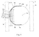
- This bag former 10 is detachably attached on a front upper surface of the machine framework 2 and is, as shown in Fig. 3, so designed and so structured that while a strip CC of packaging material drawn forwards E from the roll of the packaging material are being guided downwards, opposite side edges CC1 and CC2 of the strip CC1 of packaging material shown in Fig. 4 can be overlapped with each other.
- an upper portion 14 of the tube member 13 that protrudes outwards from the sailor member 12 is of a generally inverted conical shape having been upwardly flared to define a receiving opening into which articles to be bagged can be supplied from above.
- a lower portion of the tube member 13 that protrudes downwards from the sailor member 12 is adapted to protrude into the packaging material, then formed into a tubular form, to supply the articles into the tubular packaging material.
- belt-type feeding devices 3 and 3 are disposed with their belts capable of running in a direction generally parallel to the longitudinal direction of the tubular packaging material. These belt-type feeding devices 3 and 3 urges circumferentially opposite portions of the tubular packaging material against outer surface areas 15aa and 15aa of correspondingly circumferentially opposite side walls 15a and 15a of the lower portion 15 so as to draw the tubular packaging material downwards.
- the overlapping side edges CC1 and CC2 (Fig.
- the front wall 15b and the side walls 15a and 15a do not lie perpendicular to each other and the lower portion 15 of the tube member 13 has front and side walls 15b and 15a are connected, or otherwise continued, to each other through curved connecting walls 15d and 15d so that the lower portion 15 of the tube member has its sectional corners that are generally curved.
- a transverse sealing device 6 capable of performing a sequential process of clamping the tubular packaging material, of which overlapping side edges thereof have been sealed by the longitudinal sealing unit 5, that is, clamping the longitudinally sealed tubular packaging material from front and rear directions to fuse a predetermined position of the longitudinally sealed tubular packaging material in a transverse direction perpendicular to the direction of feed of the packaging material, cutting the predetermined position of the longitudinally sealed tubular packaging material in the transverse direction to thereby leave a bottom seal in the longitudinally sealed tubular packaging material above the transverse cut line, and forming, after the articles have been filled in a portion of the longitudinally sealed packaging material above the bottom seal, a top seal below the transverse cut line thereby leaving a bagged product.
- a substitute gas supply passage 20 for the supply of an inert gas into the article filled bag to replace with the air within the article filled bag is defined inside the tube member 13 as best shown in Figs. 5 and 6 on an enlarged scale.
- the substitute gas supply passage 20 is formed by securing to respective inner surfaces of the connecting walls 15d and 15d that connect the front and side walls 15b and 15a of the tube member 13 together, a generally elongated plate 21 of a length sufficient to extend from the upper portion 14 down to the lower end of the lower portion 15 of the tube member so that a longitudinally extending space, which eventually forms the substitute gas supply passage 20, can be formed between the elongated plate 21 and the front wall 15b of the tube member 13.
- the substitute gas supply passage 20 has an upper end thereof closed by bending an upper end of the elongated plate 21 to connect it to an inner surface of the upper portion 14 of the tube member 13.
- a gas supply port 22 is formed exteriorly on a front wall of the upper portion 14 of the tube member 13 and is communicated with the substitute gas supply passage 20.
- a gas supply piping (not shown) is adapted to be connected with the gas supply port 20.
- the substitute gas supply passage 20 has a lower end left open to thereby define a gas outlet 23.
- a lower portion 20a of the substitute gas supply passage 20 delimited by the elongated plate 21 and the front wall 15b and respective portions of the connecting walls 15d and 15d of the lower portion 15 of the tube member 13 is so designed and so shaped as to be spaced inwardly away from the inner surface of the front wall 15b of the tube member 13 a distance greater than that at an upper portion of the substitute gas supply passage 20, such that the flat cross-section of the substitute gas supply passage 20 can represent a shape having a width x and a thickness y, as shown in Fig. 4, which are greater than those at an upper portion of the substitute gas supply passage 20.
- the substitute gas supply passage 20 has a cross-sectional area that is greater at the lower end thereof than at the upper end thereof.
- the width x of the cross-sectional shape of the substitute gas supply passage 20 can be increased to have a greater value at the lower end thereof than at the upper end thereof merely by securing the elongated plate 21 in an inclined fashion is because the front wall 15b and the side walls 15a of the tube member 13 are connected together by means of the curved connecting walls 15d and 15d and the width x can therefore increase as the elongated plate 21 separates away from the inner surface of the front wall 15b of the tube member 13.
- the strip CC of packaging material shown in Fig. 3 is drawn forwards F from the roll (not shown) at the rear of the machine framework 2.
- the strip CC of packaging material so drawn is fed downwards at a front upper region of the machine framework 2 shown in Fig. 1, the strip CC of packaging material is longitudinally curled by the sailor member 12, forming a part of the tube former 10, with the longitudinal side edges CC1 and CC2 (Fig.4) thereof consequently overlapped with each other.
- the strip CC of packaging material is further fed downwards by the feed devices 3 and 3 and the overlapping side edges CC1 and CC2 of the tubular packaging material are fusion bonded together by means of the longitudinal sealing device 5 at the outer surface 15ba of the front wall 15b on the lower portion 15 of the tube member 13 to thereby form the longitudinally sealed tubular packaging material.
- a lower portion of the longitudinally sealed tubular packaging material has already been sealed by the transverse sealing device 6 during the previous cycle of bagging operation and, therefore, the longitudinally sealed tubular packaging material is substantially in the form of a bag having its bottom sealed.
- the bag-shaped longitudinally sealed tubular packaging material now identified by C in Fig. 7, is further fed downwards and then filled with the articles X, X ⁇ X supplied thereinto from above through the tube member 13.
- an inert gas such as, for example, nitrogen gas or argon gas is supplied from an external gas supply device (not shown) into the bag-shaped longitudinally sealed tubular packaging material C through the substitute gas supply passage 20.
- an inert gas is so supplied, air inside the bag-shaped longitudinally sealed tubular packaging material C is expelled out of the bag-shaped longitudinally sealed tubular packaging material C through, for example, the upper end of the tube member 13 or through a package curling unit constituted by, for example, the sailor member 12 (See Fig. 3) and is therefore replaced with the inert gas.
- a portion of the bag-shaped longitudinally sealed tubular packaging material C above the filled articles X, X ⁇ X is heat sealed by a pair of bar members 6a and 6a of the transverse sealing device 6 and is, simultaneously therewith, cut to separate from an upstream portion of the longitudinally sealed tubular packaging material to thereby complete production of a bagged product which subsequently fall by gravity downwards onto the delivery device 7.
- a lower end of the upstream portion of the longitudinally sealed tubular packaging material is sealed to define a bottom seal to render the tubular packaging material to be a bag-shaped longitudinally sealed tubular packaging material C in readiness for the subsequent cycle of article filling.
- the bagged products each containing a predetermined quantity of articles filled therein and also containing the inert gas filled therein in place of the air can be continuously manufactured and successively transported by the delivery device 7 (See Fig. 1) towards the next subsequent processing station out of the bagging and packaging machine 1.
- the lower portion 20a of the substitute gas supply passage 20 has a cross-sectional area that progressively increases downwards thereof, the velocity of flow of the inert gas at the time of being introduced into the bag-shaped longitudinally sealed tubular packaging material C through the gas outlet 23 at the lower end of the substitute gas supply passage 20 is relatively low even though the velocity of flow of the inert gas at the gas supply port 22 is increased in concomitance with increase of the packaging speed.
- the inert gas is vigorously introduced into the bag-shaped longitudinally sealed tubular packaging material C, accompanied by blow-up of some or all of the articles X, X ⁇ X within the bag-shaped longitudinally sealed tubular packaging material C and/or any possible disturbance to the introduction of the articles X, X ⁇ X into the bag-shaped longitudinally sealed tubular packaging material C.
- the articles X, X ⁇ X can be satisfactorily and effectively introduced into the bag-shaped longitudinally sealed tubular packaging material C and, also, any possible biting of some of the articles X, X ⁇ X by the paired bar members 6a and 6a of the transverse sealing device 6 can also be eliminated.
- the substitute gas supply passage 20 since the substitute gas supply passage 20 has its upper portion having a relatively small cross-sectional area, the cross-sectional area of the tube member 13 itself will not be sacrificed and, accordingly, even at the upper portion of the tube member 13 which is not left open at the rear side thereof, fall of the articles to be supplied into the bag-shaped longitudinally sealed tubular packaging material C is not hampered.
- the gas outlet 23 at the lower end of the substitute gas supply passage 20 is opened in a direction outwardly of the tube member 13, there is no possibility of an air curtain of the substitute gas being formed at a lower open end of the tube member 13, thereby eliminating the possibility that introduction of the articles X, X ⁇ X into the bag-shaped longitudinally sealed tubular packaging material C will be hampered.
- the substitute gas supply passage 20 has been shown and described as formed between the front wall 15b of the tube member 13 and the elongated plate 21, effects similar to those described hereinabove can be obtained even when a tubular substitute gas supply pipe having a cross-sectional area that is greater at the lower portion thereof than at the upper portion is disposed within the tube member 13.
Landscapes
- Chemical & Material Sciences (AREA)
- Dispersion Chemistry (AREA)
- Engineering & Computer Science (AREA)
- Mechanical Engineering (AREA)
- Containers And Plastic Fillers For Packaging (AREA)
- Vacuum Packaging (AREA)
Abstract
Description
- The present invention generally relates to the art of packaging and, more particularly to a bagging and packaging machine for successively forming bags from a strip of bag material and subsequently packaging an article into each of the bags.
- In general, the bagging and packaging machine for successively forming bags from a strip of bag material and subsequently packaging an article into each of the bags undergoes a process of forming the strip of bag material, supplied to a bag former, into a tubular form by means of the bag former by overlapping opposite longitudinal side edges with each other; fusion bonding, by means of a longitudinal sealing unit, the overlapped longitudinal side edges of the tubular strip of bag material in a direction longitudinally thereof at an outer surface of a front wall of an article introducing tube member forming a part of the bag former and, concurrently, fusion bonding the tubular strip of bag material in a direction perpendicular to the longitudinal sense of the tubular strip of bag material to form a bottom seal by means of a transverse sealing unit. After an article has been introduced into the tubular strip of bag material through the article introducing tube member, the machine carries out fusion bonding an upper portion of the tubular strip of bag material by means of the transverse sealing unit to form an upper seal to seal the article within the tubular strip of bag material; and finally cutting the tubular strip of bag material along the upper seal to thereby to produce a bagged product containing the article sealed within the bag.
- In the practice of this process, where the article filled in each of the successively formed bags is food material, it is a general practice to form the upper seal in the bag after an inert gas such as, for example, nitrogen gas or argon gas has been substituted for air within the bag containing the article therein. The Japanese Laid-open Patent Publication No. 10-53217, for example, discloses the technique necessitated for this purpose.
- The gas replacement device disclosed in the above mentioned publication includes, as shown in Fig. 8, a substitute gas supply passage B extending in a vertical direction along an inner surface of the article introducing tube member A, which passage B has a gas inlet B1 defined at an upper end thereof and a gas outlet B2 defined at a lower end thereof. An inert gas to be substituted for the air within the bag is supplied into the substitute gas supply passage B through the gas inlet B1 and is discharged through the gas outlet B2 into the bag-shaped packaging material C. The inert gas thus supplied into the bag-shaped packaging material C expels the air therefrom so that the inert gas can substitute for the air.
- On the other hand, in recent years, the handling capacity of the packaging machine has been desired to increase further. If the rate of replacement with the inert gas is desired to be maintained at a high level in an attempt to increase the handling speed, the flow rate or velocity of the inert gas has to be increased so that the amount of the inert gas supplied per unitary time can be increased. However, increase of the gas flow velocity tends to result in that as shown in Fig. 8, the inert gas is vigorously introduced from the gas outlet B2 at the lower end of the substitute gas supply passage B into the bag-shaped packaging material C and, consequently, some of items X, X, ···· X of the article to be bagged are blown upwardly within the bag-shaped packaging material C or a sufficient introduction of the items X, X, ···· X of the article towards the bottom of the bag-shaped packaging material C is hampered. In such case, when the upper seal is to be formed in the filled bag-shaped packaging material C by means of the transverse sealers D and D of the transverse sealing unit, some of the items X, X, ···· X of the article which have been blown upwards within the bag-shaped packaging material C or which have been retarded to reach the bottom of the bag-shaped packaging material C are often "bitten" by the transverse sealers D and D, resulting in a defective bagged product.
- In an attempt to obviate problems brought about by the blow-up within the bag-shaped packaging material C, it may be contemplated to increase the cross-sectional area of the substitute gas supply passage B over the entire length thereof. However, increase of the cross-sectional area of the substitute gas supply passage B necessitates reduction of the cross-sectional area of the tube member A, which in turn results in lowering the speed at which the items X, X, ···· X of the article are introduced into the bag-shaped packaging material C through the tube member A or clogging of some of the items X, X, ···· X of the article within the tube member A. The consequence is that introduction of a required or desired quantity of the items X, X, ···· X of the article into the bag-shaped packaging material C through the tube member A will take a relatively long time, hampering a high speed packaging operation, or otherwise a possibility will arise that some of the bagged products may contain an insufficient quantity of the items X, X, ···· X of the article.
- Also with the prior art structure disclosed in the previously discussed publication, since as shown in Fig. 8 the gas outlet B2 at the lower end of the substitute gas supply passage B opens inwardly of the tube member A, an air curtain of the inert gas discharged from the substitute gas supply passage B is formed at a lower end region of the tube member A, hampering a smooth introduction of the article into the bag-shaped packaging material C through the tube member A. As a result, the handling speed during the packaging operation tends to be lowered, or a possibility will arise that some of the bagged products may contain insufficient quantity of the items X, X, ···· X of the article.
- Accordingly, the present invention has been devised to provide an improved bagging and packaging machine of a type having a gas flush capability, in which the inert gas can be sufficiently introduced to achieve a high rate of gas replacement with neither possibility of the article being bitten, or possibility of the packaging speed being lowered during the sealing of the filled bag.
- In order to obviate the problems discussed above, the present invention is featured in that the bagging and packaging machine is constructed as follows.
- In the first place, the present invention provides a bagging and packaging machine which includes a bag former including a sailor member and a tube member connected with the sailor member and operable to form a strip of packaging material into a tubular form with opposite longitudinal side edges thereof overlapping with each other, a vertical sealing means for sealing the overlapping longitudinal side edges of the strip of packaging material, which has been formed into the tubular form by the bag former, to provide a longitudinally sealed tubular packaging material, a transverse sealing means for sealing the longitudinally sealed tubular packaging material in a direction generally perpendicular to a longitudinal sense of the longitudinally sealed tubular packaging material to render the latter in a bag form, with articles being introduced into the bag-shaped longitudinally sealed tubular packaging material through the tube member. The bagging and packaging machine further includes a substitute gas supply passage provided inside the tube member for introducing a substitute gas into the bag-shaped longitudinally sealed tubular packaging material for replacement with air inside the bag-shaped longitudinally sealed tubular packaging material. The substitute gas supply passage has a cross-sectional area that is greater at a downstream side thereof than at an upstream side thereof with respect to a direction of flow of the substitute gas.
- Preferably, the substitute gas supply passage has a cross-sectional shape having a width that is large at the downstream side thereof such that the substitute gas supply passage has a cross-sectional area that is larger at the downstream side thereof than at the upstream side thereof.
- Alternatively or in combination therewith, the substitute gas supply passage preferably has a cross-sectional shape having a thickness that is large at the downstream side thereof such that the substitute gas supply passage has a cross-sectional area that is larger at the downstream side thereof than at the upstream side thereof.
- Also preferably, the substitute gas supply passage has a downstream end at the downstream side thereof that is left open in a direction outwardly of the tube member.
- In addition, a longitudinal portion of the tube member, which confronts a wall having a surface where the opposite longitudinal side edges of the strip of packaging material are overlapped, is preferably left open.
- According to the present invention, since the substitute gas supply passage provided in the tube member forming a part of the bag former has a cross-sectional area that is larger at the downstream side thereof than at the upstream side thereof, it is possible to supply a required quantity of the substitute gas into the bag-shaped longitudinally sealed tubular packaging material at a relatively moderate flow velocity through the opening at the lower end thereof without the cross-sectional area of the article introducing passage within the tube member being unnecessarily narrowed such as occurring in the case where the substitute gas supply passage has a large cross-sectional area over the entire length thereof from the upstream side down to the downstream side thereof.
- Accordingly, without the efficiency of the packaging operation being lowered, and also without the rate of replacement of the gas being lowered, the inconvenience hitherto experienced with the biting of some of the articles which occur when some of the articles within the bag-shaped longitudinally sealed tubular packaging material are blown up by the flow of the substitute gas can advantageously be avoided, thereby avoiding production of defective bagged products.
- According to a preferred embodiment of the present invention, since the substitute gas supply passage has a cross-sectional shape having a width that is large at the downstream side thereof and/or having a thickness that is large at the downstream side thereof, the cross-sectional area of the substitute gas supply passage can easily be set larger at the downstream side thereof than at the upstream side thereof.
- Also, according to a preferred embodiment of the present invention, since the end of the substitute gas supply passage at the downstream side thereof is left open outwardly of the tube member, there is no possibility that an air curtain of the substitute gas emerging from that opening will be formed at the gas outlet of the tube member, thereby eliminating the possibility that introduction of the articles into the bag-shaped longitudinally sealed tubular packaging material will be hampered.
- Again, according to a preferred embodiment of the present invention, since the longitudinal portion of the tube member, which confronts a wall having a surface where the opposite longitudinal side edges of the strip of packaging material are overlapped, is left open, any clogging of the articles to be bagged is advantageously avoided and thus, the introduction of the articles to be bagged through the tube member can take place smoothly in view of the additional fact that the cross-sectional area of the upstream portion of the substitute gas supply passage is so narrowed to secure a sufficient cross-sectional area of the tube member for the introduction of the articles therethrough. Accordingly, any possible reduction of the handling speed can advantageously be further avoided.
- In any event, the present invention will become more clearly understood from the following description of a preferred embodiment thereof, when taken in conjunction with the accompanying drawings. However, the embodiment and the drawings are given only for the purpose of illustration and explanation, and are not to be taken as limiting the scope of the present invention in any way whatsoever, which scope is to be determined by the appended claims. In the accompanying drawings, like reference numerals are used to denote like parts throughout the several views, and:
- Fig. 1 is a schematic front elevational view of a bagging and packaging machine embodying the present invention;
- Fig. 2 is a front elevational view, on an enlarged scale, of a bag former employed in the bagging and packaging machine;
- Fig. 3 is a side view, on an enlarged scale, of the bag former employed in the bagging and packaging machine;
- Fig. 4 is a cross-sectional view taken along the line IV-IV in Fig. 3, showing a transverse section of a supply tube;
- Fig. 5 is a cross-sectional view, on an enlarged scale, taken along the line V-V in Fig. 2, showing a side section of an upper portion of the supply tube;
- Fig. 6 is a cross-sectional view , on an enlarged scale, taken along the line VI-VI in Fig. 2, showing a side section of a lower portion of the supply tube;
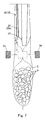
- Fig. 7 is an explanatory diagram showing the manner in which a substitute gas is introduced in a lower region of the supply tube; and
- Fig. 8 is a schematic side sectional view used to explain the problems inherent in the prior art substitute gas supply passage.
-
- Hereinafter, a preferred embodiment of the present invention will be described in detail. Referring first to Fig. 1, a bagging and
packaging machine 1 embodying the present invention includes amachine framework 2 having a rear upper portion, on which a roll support structure (not shown) for rotatably supporting a roll of packaging material is fixedly mounted, and a front upper portion on which a bag former 10 is mounted. - The bag former 10 is of a unitary structure including a
frame 11 on which asailor member 12 and atube member 13 extending vertically through thesailor member 12 are mounted (See particularly Figs. 2 and 3). This bag former 10 is detachably attached on a front upper surface of themachine framework 2 and is, as shown in Fig. 3, so designed and so structured that while a strip CC of packaging material drawn forwards E from the roll of the packaging material are being guided downwards, opposite side edges CC1 and CC2 of the strip CC1 of packaging material shown in Fig. 4 can be overlapped with each other. - In Fig. 1 an
upper portion 14 of thetube member 13 that protrudes outwards from thesailor member 12 is of a generally inverted conical shape having been upwardly flared to define a receiving opening into which articles to be bagged can be supplied from above. A lower portion of thetube member 13 that protrudes downwards from thesailor member 12 is adapted to protrude into the packaging material, then formed into a tubular form, to supply the articles into the tubular packaging material. - On left and right sides of the
lower portion 15 of thetube member 13, belt-type feeding devices type feeding devices opposite side walls lower portion 15 so as to draw the tubular packaging material downwards. The overlapping side edges CC1 and CC2 (Fig. 4) of the tubular packaging material that are so formed by the bag former 10 are, as the tubular packaging material is drawn downwards by the belt-type feeding devices vertical sealing device 5 that is supported at the front of themachine framework 2 by means of a support arm 4. - The circumferentially opposite outer surface areas 15aa and 15aa of the
side walls lower portion 15 of thetube member 13, with which therespective feeding devices front wall 15b on thelower portion 15 of thetube member 13 with which thevertical sealing device 5 are brought into contact to fusion bond the overlapping side edges of the tubular packaging material are formed as respective flat surface areas. At the same time, arear side 15c of thelower portion 15 of thetube member 13 that is opposite to thefront wall 15b is left open to thereby render the cross-section of thelower portion 15 of thetube member 13 to represent a generally C-sectioned configuration as clearly shown in Fig. 4. In other words, thefront wall 15b and theside walls lower portion 15 of thetube member 13 has front andside walls walls lower portion 15 of the tube member has its sectional corners that are generally curved. - Referring again to Fig. 1, somewhat beneath a lower end of the
lower portion 15 of thetube member 13 and at the front of themachine framework 2, there is disposed atransverse sealing device 6 capable of performing a sequential process of clamping the tubular packaging material, of which overlapping side edges thereof have been sealed by thelongitudinal sealing unit 5, that is, clamping the longitudinally sealed tubular packaging material from front and rear directions to fuse a predetermined position of the longitudinally sealed tubular packaging material in a transverse direction perpendicular to the direction of feed of the packaging material, cutting the predetermined position of the longitudinally sealed tubular packaging material in the transverse direction to thereby leave a bottom seal in the longitudinally sealed tubular packaging material above the transverse cut line, and forming, after the articles have been filled in a portion of the longitudinally sealed packaging material above the bottom seal, a top seal below the transverse cut line thereby leaving a bagged product. Adelivery device 7 for transporting the bagged product towards the subsequent processing station out of the bagging andpackaging machine 1 - While the bagging and
packaging machine 1 is so constructed as hereinabove described, a substitutegas supply passage 20 for the supply of an inert gas into the article filled bag to replace with the air within the article filled bag is defined inside thetube member 13 as best shown in Figs. 5 and 6 on an enlarged scale. More specifically, the substitutegas supply passage 20 is formed by securing to respective inner surfaces of theconnecting walls side walls tube member 13 together, a generallyelongated plate 21 of a length sufficient to extend from theupper portion 14 down to the lower end of thelower portion 15 of the tube member so that a longitudinally extending space, which eventually forms the substitutegas supply passage 20, can be formed between theelongated plate 21 and thefront wall 15b of thetube member 13. - As best shown in Fig. 5, the substitute
gas supply passage 20 has an upper end thereof closed by bending an upper end of theelongated plate 21 to connect it to an inner surface of theupper portion 14 of thetube member 13. Agas supply port 22 is formed exteriorly on a front wall of theupper portion 14 of thetube member 13 and is communicated with the substitutegas supply passage 20. A gas supply piping (not shown) is adapted to be connected with thegas supply port 20. Also, as best shown in Fig. 6, the substitutegas supply passage 20 has a lower end left open to thereby define agas outlet 23. - A
lower portion 20a of the substitutegas supply passage 20 delimited by theelongated plate 21 and thefront wall 15b and respective portions of the connectingwalls lower portion 15 of thetube member 13 is so designed and so shaped as to be spaced inwardly away from the inner surface of thefront wall 15b of the tube member 13 a distance greater than that at an upper portion of the substitutegas supply passage 20, such that the flat cross-section of the substitutegas supply passage 20 can represent a shape having a width x and a thickness y, as shown in Fig. 4, which are greater than those at an upper portion of the substitutegas supply passage 20. Thus, the substitutegas supply passage 20 has a cross-sectional area that is greater at the lower end thereof than at the upper end thereof. The fact that the width x of the cross-sectional shape of the substitutegas supply passage 20 can be increased to have a greater value at the lower end thereof than at the upper end thereof merely by securing theelongated plate 21 in an inclined fashion is because thefront wall 15b and theside walls 15a of thetube member 13 are connected together by means of the curved connectingwalls elongated plate 21 separates away from the inner surface of thefront wall 15b of thetube member 13. - Also, as shown in Fig. 6, positioning a lower end 21' of the
elongated plate 21 at a location below a lower end 15' of thefront wall 15b of thetube member 13 renders thegas outlet 23 to open towards the front wall, that 15b is, outwardly of thetube member 13. - Hereinafter, the operation of the bagging and
packaging machine 1 embodying the present invention will be described. - When the bagging and
packaging machine 1 in Fig. 1 is in operation, the strip CC of packaging material shown in Fig. 3 is drawn forwards F from the roll (not shown) at the rear of themachine framework 2. As the strip CC of packaging material so drawn is fed downwards at a front upper region of themachine framework 2 shown in Fig. 1, the strip CC of packaging material is longitudinally curled by thesailor member 12, forming a part of the tube former 10, with the longitudinal side edges CC1 and CC2 (Fig.4) thereof consequently overlapped with each other. The strip CC of packaging material is further fed downwards by thefeed devices longitudinal sealing device 5 at the outer surface 15ba of thefront wall 15b on thelower portion 15 of thetube member 13 to thereby form the longitudinally sealed tubular packaging material. At this time, a lower portion of the longitudinally sealed tubular packaging material has already been sealed by thetransverse sealing device 6 during the previous cycle of bagging operation and, therefore, the longitudinally sealed tubular packaging material is substantially in the form of a bag having its bottom sealed. Thereafter, the bag-shaped longitudinally sealed tubular packaging material, now identified by C in Fig. 7, is further fed downwards and then filled with the articles X, X ···· X supplied thereinto from above through thetube member 13. - Simultaneously with filling of the articles X, X ···· X into the bag-shaped longitudinally sealed tubular packaging material C, an inert gas such as, for example, nitrogen gas or argon gas is supplied from an external gas supply device (not shown) into the bag-shaped longitudinally sealed tubular packaging material C through the substitute
gas supply passage 20. As the inert gas is so supplied, air inside the bag-shaped longitudinally sealed tubular packaging material C is expelled out of the bag-shaped longitudinally sealed tubular packaging material C through, for example, the upper end of thetube member 13 or through a package curling unit constituted by, for example, the sailor member 12 (See Fig. 3) and is therefore replaced with the inert gas. - Thereafter, as shown by the phantom lines in Fig. 7, a portion of the bag-shaped longitudinally sealed tubular packaging material C above the filled articles X, X ···· X is heat sealed by a pair of
bar members transverse sealing device 6 and is, simultaneously therewith, cut to separate from an upstream portion of the longitudinally sealed tubular packaging material to thereby complete production of a bagged product which subsequently fall by gravity downwards onto thedelivery device 7. It is to be noted that a lower end of the upstream portion of the longitudinally sealed tubular packaging material is sealed to define a bottom seal to render the tubular packaging material to be a bag-shaped longitudinally sealed tubular packaging material C in readiness for the subsequent cycle of article filling. - In this way, the bagged products each containing a predetermined quantity of articles filled therein and also containing the inert gas filled therein in place of the air can be continuously manufactured and successively transported by the delivery device 7 (See Fig. 1) towards the next subsequent processing station out of the bagging and
packaging machine 1. - In such case, particularly in the bagging and
packaging machine 1 embodying the present invention, since thelower portion 20a of the substitutegas supply passage 20 has a cross-sectional area that progressively increases downwards thereof, the velocity of flow of the inert gas at the time of being introduced into the bag-shaped longitudinally sealed tubular packaging material C through thegas outlet 23 at the lower end of the substitutegas supply passage 20 is relatively low even though the velocity of flow of the inert gas at thegas supply port 22 is increased in concomitance with increase of the packaging speed. - Accordingly, there is no possibility that the inert gas is vigorously introduced into the bag-shaped longitudinally sealed tubular packaging material C, accompanied by blow-up of some or all of the articles X, X ···· X within the bag-shaped longitudinally sealed tubular packaging material C and/or any possible disturbance to the introduction of the articles X, X ···· X into the bag-shaped longitudinally sealed tubular packaging material C. Thus, with the bagging and packaging machine embodying the present invention, the articles X, X ···· X can be satisfactorily and effectively introduced into the bag-shaped longitudinally sealed tubular packaging material C and, also, any possible biting of some of the articles X, X ···· X by the paired
bar members transverse sealing device 6 can also be eliminated. - Also, since the substitute
gas supply passage 20 has its upper portion having a relatively small cross-sectional area, the cross-sectional area of thetube member 13 itself will not be sacrificed and, accordingly, even at the upper portion of thetube member 13 which is not left open at the rear side thereof, fall of the articles to be supplied into the bag-shaped longitudinally sealed tubular packaging material C is not hampered. In addition, since thegas outlet 23 at the lower end of the substitutegas supply passage 20 is opened in a direction outwardly of thetube member 13, there is no possibility of an air curtain of the substitute gas being formed at a lower open end of thetube member 13, thereby eliminating the possibility that introduction of the articles X, X ···· X into the bag-shaped longitudinally sealed tubular packaging material C will be hampered. - Furthermore, according to the foregoing embodiment of the present invention, since the
rear side 15c of thelower portion 15 of thetube member 13 that is enclosed by the longitudinally sealed tubular packaging material is left open, clogging of the articles X,X ···· X will not occur at that portion inside thetube member 13 and, accordingly, introduction of the articles into the bag-shaped longitudinally sealed tubular packaging material C through thetube member 13 takes place smoothly, thereby facilitating filling of the articles to the bottom of the bag-shaped longitudinally sealed tubular packaging material C. - Thus, it has now become clear that while any possible reduction of the handling speed during the bagging and packaging operation is avoided, and the quantity of the inert gas supplied per unitary time is increased to attain a high gas replacement rate even when the handling speed is increased, production of defective bagged products which would result from the biting of the articles in the seals can be prevented advantageously.
- Although the present invention has been fully described in connection with the preferred embodiment thereof with reference to the accompanying drawings which are used only for the purpose of illustration, those skilled in the art will readily conceive numerous changes and modifications within the framework of obviousness upon the reading of the specification herein presented of the present invention.
- By way of example, although in the foregoing embodiment of the present invention, the substitute
gas supply passage 20 has been shown and described as formed between thefront wall 15b of thetube member 13 and theelongated plate 21, effects similar to those described hereinabove can be obtained even when a tubular substitute gas supply pipe having a cross-sectional area that is greater at the lower portion thereof than at the upper portion is disposed within thetube member 13.
Claims (5)
- A bagging and packaging machine which comprises:a bag former including a sailor member and a tube member connected with the sailor member and operable to form a strip of packaging material into a tubular form with opposite longitudinal side edges thereof overlapping with each other;a vertical sealing means for sealing the overlapping longitudinal side edges of the strip of packaging material, which has been formed into the tubular form by the bag former, to provide a longitudinally sealed tubular packaging material;a substitute gas supply passage provided inside the tube member for introducing a substitute gas into the bag-shaped longitudinally sealed tubular packaging material for replacement of air inside the bag-shaped longitudinally sealed tubular packaging material, said substitute gas supply passage having a cross-sectional area that is greater at a downstream side thereof than at an upstream side thereof with respect to a direction of flow of the substitute gas; anda transverse sealing means for sealing the longitudinally sealed tubular packaging material in a direction generally perpendicular to a longitudinal sense of the longitudinally sealed tubular packaging material to render the latter in a bag form, with articles being introduced into the bag-shaped longitudinally sealed tubular packaging material through the tube member.
- The bagging and packaging machine as claimed in Claim 1, wherein the substitute gas supply passage has a cross-sectional shape having a width that is large at the downstream side thereof such that the substitute gas supply passage has a cross-sectional area that is larger at the downstream side thereof than at the upstream side thereof.
- A machine according to claim 1 or claim 2, wherein the substitute gas supply passage has a cross-sectional shape having a thickness that is large at the downstream side thereof such that the substitute gas supply passage has a cross-sectional area that is larger at the downstream side thereof than at the upstream side thereof.
- A machine according to any of the preceding claims, wherein the substitute gas supply passage has a downstream end at the downstream side thereof that is left open in a direction outwardly of the tube member.
- A machine according to any of the preceding claims, wherein a longitudinal portion of the tube member, which confronts a wall having a surface where the opposite longitudinal side edges of the strip of packaging material are overlapped, is left open.
Applications Claiming Priority (2)
| Application Number | Priority Date | Filing Date | Title |
|---|---|---|---|
| JP22959899 | 1999-08-16 | ||
| JP22959899A JP4408489B2 (en) | 1999-08-16 | 1999-08-16 | Bag making and packaging machine |
Publications (2)
| Publication Number | Publication Date |
|---|---|
| EP1077176A1 true EP1077176A1 (en) | 2001-02-21 |
| EP1077176B1 EP1077176B1 (en) | 2004-03-03 |
Family
ID=16894699
Family Applications (1)
| Application Number | Title | Priority Date | Filing Date |
|---|---|---|---|
| EP00306958A Expired - Lifetime EP1077176B1 (en) | 1999-08-16 | 2000-08-15 | Bagging and packaging machine capable of sufficiently filling an inert gas into bags |
Country Status (4)
| Country | Link |
|---|---|
| US (1) | US6619018B1 (en) |
| EP (1) | EP1077176B1 (en) |
| JP (1) | JP4408489B2 (en) |
| DE (1) | DE60008652T2 (en) |
Cited By (6)
| Publication number | Priority date | Publication date | Assignee | Title |
|---|---|---|---|---|
| WO2005082717A1 (en) | 2004-02-26 | 2005-09-09 | Ishida Co., Ltd. | Packaging machine |
| US7152387B2 (en) | 2004-01-06 | 2006-12-26 | Tna Australia Pty Limited | Packaging machine and former |
| EP1538082A4 (en) * | 2002-07-30 | 2009-09-09 | Ishida Seisakusho | Packing machine, packing method, and packing system |
| WO2012145757A1 (en) * | 2011-04-21 | 2012-10-26 | J & F Business, Inc. | Bag former assembly |
| CN106428732A (en) * | 2016-10-18 | 2017-02-22 | 安徽智泓净化科技股份有限公司 | Packaging plant of water purification assembly |
| GB2489111B (en) * | 2011-03-17 | 2017-02-22 | Tna Australia Pty Ltd | A packaging machine former |
Families Citing this family (13)
| Publication number | Priority date | Publication date | Assignee | Title |
|---|---|---|---|---|
| AU2003903509A0 (en) * | 2003-07-08 | 2003-07-24 | Tna Australia Pty Limited | A packaging machine former support |
| KR100715501B1 (en) | 2004-08-12 | 2007-05-07 | 쓰리애플즈코스메틱스 주식회사 | Anaerobic Automatic Forming Fill Packing Machine |
| ITBO20040534A1 (en) * | 2004-08-26 | 2004-11-26 | Gino Rapparini | PROCESS FOR ASEPTIC PACKAGING OF STERL LIQUIDS IN FLEXIBLE CONTAINERS |
| US20060213153A1 (en) * | 2005-03-03 | 2006-09-28 | Sanfilippo James J | Device and system for modified atmosphere packaging |
| US7523597B2 (en) * | 2007-03-20 | 2009-04-28 | J & F Business, Inc. | Apparatus and method for mounting a bag former |
| US7891156B2 (en) * | 2009-03-24 | 2011-02-22 | Rethceif Enterprises, Llc | Packaging apparatus and method of packaging |
| CN102686483B (en) * | 2009-12-18 | 2014-06-11 | 利乐拉瓦尔集团及财务有限公司 | Filling assembly, gasket for use in the filling assembly, and a method for filling liquid |
| CA2834852C (en) * | 2011-05-04 | 2021-06-01 | Dole Fresh Vegetables, Inc. | A gas flushing system for reducing oxygen content in packaged produce |
| JP5882155B2 (en) * | 2012-07-23 | 2016-03-09 | 株式会社イシダ | Packaging equipment |
| EP3003877B1 (en) * | 2013-06-04 | 2017-04-12 | Tetra Laval Holdings & Finance SA | Device and method in a filling machine |
| JP5952225B2 (en) | 2013-06-26 | 2016-07-13 | 株式会社椿本チエイン | Chain tensioner |
| JP7677613B2 (en) * | 2021-03-11 | 2025-05-15 | 株式会社イシダ | Bag making and packaging equipment |
| JP2024082383A (en) * | 2022-12-08 | 2024-06-20 | 株式会社イシダ | Bag making and packaging equipment |
Citations (1)
| Publication number | Priority date | Publication date | Assignee | Title |
|---|---|---|---|---|
| CH388174A (en) * | 1961-10-14 | 1965-02-15 | Hamac Hansella Ag Maschinenfab | Method and device for extracting excess air from tubular bag packs |
Family Cites Families (9)
| Publication number | Priority date | Publication date | Assignee | Title |
|---|---|---|---|---|
| US2145941A (en) * | 1938-04-18 | 1939-02-07 | Stokes & Smith Co | Method of and apparatus for making packages |
| US3664086A (en) * | 1969-12-29 | 1972-05-23 | Hayssen Mfg Co | Gas flushing system for vertical form, fill and seal machines |
| DE2931527A1 (en) * | 1978-09-29 | 1980-04-17 | Sig Schweiz Industrieges | DEVICE FOR PRODUCING AND FILLING HOSE BAGS |
| DE3210102A1 (en) * | 1981-10-24 | 1983-05-05 | Robert Bosch Gmbh, 7000 Stuttgart | DEVICE FOR FILLING QUANTITIES OF GOODS IN PACKAGING CONTAINERS |
| US4640083A (en) * | 1983-05-31 | 1987-02-03 | Tokyo Automatic Machinery Works, Ltd. | Apparatus for producing bags and packing articles therein |
| US4563862A (en) * | 1984-10-23 | 1986-01-14 | Kliklok Corporation | Package forming apparatus with combined holding and stripper mechanism |
| CH667246A5 (en) * | 1985-02-18 | 1988-09-30 | Ilapak Res & Dev Sa | VERTICAL TUBE MACHINE. |
| US4964259A (en) * | 1989-08-02 | 1990-10-23 | Borden, Inc. | Form-fill-seal deflation method and apparatus |
| DE19852107A1 (en) * | 1998-11-12 | 2000-05-18 | Rovema Gmbh | Packaging device and method |
-
1999
- 1999-08-16 JP JP22959899A patent/JP4408489B2/en not_active Expired - Lifetime
-
2000
- 2000-08-15 DE DE60008652T patent/DE60008652T2/en not_active Expired - Lifetime
- 2000-08-15 EP EP00306958A patent/EP1077176B1/en not_active Expired - Lifetime
- 2000-08-16 US US09/639,957 patent/US6619018B1/en not_active Expired - Lifetime
Patent Citations (1)
| Publication number | Priority date | Publication date | Assignee | Title |
|---|---|---|---|---|
| CH388174A (en) * | 1961-10-14 | 1965-02-15 | Hamac Hansella Ag Maschinenfab | Method and device for extracting excess air from tubular bag packs |
Cited By (10)
| Publication number | Priority date | Publication date | Assignee | Title |
|---|---|---|---|---|
| EP1538082A4 (en) * | 2002-07-30 | 2009-09-09 | Ishida Seisakusho | Packing machine, packing method, and packing system |
| US7152387B2 (en) | 2004-01-06 | 2006-12-26 | Tna Australia Pty Limited | Packaging machine and former |
| ES2276571A1 (en) * | 2004-01-06 | 2007-06-16 | Tna Australia Pty Limited | Packaging machine and former |
| ES2276571B1 (en) * | 2004-01-06 | 2008-04-16 | Tna Australia Pty Limited | PACKING MACHINE AND CONFORMATION DEVICE. |
| WO2005082717A1 (en) | 2004-02-26 | 2005-09-09 | Ishida Co., Ltd. | Packaging machine |
| EP1719704A4 (en) * | 2004-02-26 | 2007-12-19 | Ishida Seisakusho | Packaging machine |
| GB2489111B (en) * | 2011-03-17 | 2017-02-22 | Tna Australia Pty Ltd | A packaging machine former |
| WO2012145757A1 (en) * | 2011-04-21 | 2012-10-26 | J & F Business, Inc. | Bag former assembly |
| US9463886B2 (en) | 2011-04-21 | 2016-10-11 | J & F Business, Inc. | Bag former assembly |
| CN106428732A (en) * | 2016-10-18 | 2017-02-22 | 安徽智泓净化科技股份有限公司 | Packaging plant of water purification assembly |
Also Published As
| Publication number | Publication date |
|---|---|
| JP2001055206A (en) | 2001-02-27 |
| JP4408489B2 (en) | 2010-02-03 |
| US6619018B1 (en) | 2003-09-16 |
| EP1077176B1 (en) | 2004-03-03 |
| DE60008652T2 (en) | 2005-01-05 |
| DE60008652D1 (en) | 2004-04-08 |
Similar Documents
| Publication | Publication Date | Title |
|---|---|---|
| EP1077176B1 (en) | Bagging and packaging machine capable of sufficiently filling an inert gas into bags | |
| US6374579B1 (en) | Liner bag for flexible bulk container | |
| CN101137546B (en) | Sack forming, filling and sealing machine with sack lifting device and method for forming, filling and sealing sacks | |
| EP1485295B1 (en) | Vertical stand-up pouch | |
| EP1112936B1 (en) | Bagging and packaging machine capable of filling a proper quantity of inert gas into bags | |
| JP2003020004A (en) | Horizontal molding, filling, sealing device and method for forming package | |
| US20010011445A1 (en) | Apparatus for packaging products in vacuum or in a modified atmosphere | |
| US6951090B2 (en) | Packaging machine | |
| JPH1045103A (en) | Packaging device | |
| JP7677613B2 (en) | Bag making and packaging equipment | |
| US7316102B2 (en) | Apparatus for extracting air from packages | |
| JP2558132Y2 (en) | Packaging equipment | |
| JP4527226B2 (en) | Bag making and packaging machine | |
| JP2012062111A (en) | Bag making and packaging apparatus | |
| JP4486426B2 (en) | Bag making filling and packaging equipment | |
| JP7535775B2 (en) | Filling chute of vertical automatic filling packaging machine | |
| JPH0632305A (en) | Method and device for making and filling bag | |
| JPH11180417A (en) | Packaging device | |
| JP2011006141A (en) | Bag making-packaging machine | |
| JPH085466B2 (en) | Sealing device | |
| JP5882155B2 (en) | Packaging equipment | |
| JPS63162407A (en) | Package production unit | |
| JPH0479883B2 (en) | ||
| JP2021178652A (en) | Vertical bag making and packaging machine | |
| JPH09169315A (en) | Powder filling nozzle and powder filling device |
Legal Events
| Date | Code | Title | Description |
|---|---|---|---|
| PUAI | Public reference made under article 153(3) epc to a published international application that has entered the european phase |
Free format text: ORIGINAL CODE: 0009012 |
|
| AK | Designated contracting states |
Kind code of ref document: A1 Designated state(s): DE FR GB IT |
|
| AX | Request for extension of the european patent |
Free format text: AL;LT;LV;MK;RO;SI |
|
| 17P | Request for examination filed |
Effective date: 20010720 |
|
| AKX | Designation fees paid |
Free format text: DE FR GB IT |
|
| GRAP | Despatch of communication of intention to grant a patent |
Free format text: ORIGINAL CODE: EPIDOSNIGR1 |
|
| GRAS | Grant fee paid |
Free format text: ORIGINAL CODE: EPIDOSNIGR3 |
|
| GRAA | (expected) grant |
Free format text: ORIGINAL CODE: 0009210 |
|
| AK | Designated contracting states |
Kind code of ref document: B1 Designated state(s): DE FR GB IT |
|
| REG | Reference to a national code |
Ref country code: GB Ref legal event code: FG4D |
|
| REF | Corresponds to: |
Ref document number: 60008652 Country of ref document: DE Date of ref document: 20040408 Kind code of ref document: P |
|
| ET | Fr: translation filed | ||
| PLBE | No opposition filed within time limit |
Free format text: ORIGINAL CODE: 0009261 |
|
| STAA | Information on the status of an ep patent application or granted ep patent |
Free format text: STATUS: NO OPPOSITION FILED WITHIN TIME LIMIT |
|
| 26N | No opposition filed |
Effective date: 20041206 |
|
| PGFP | Annual fee paid to national office [announced via postgrant information from national office to epo] |
Ref country code: IT Payment date: 20120823 Year of fee payment: 13 Ref country code: FR Payment date: 20120906 Year of fee payment: 13 |
|
| REG | Reference to a national code |
Ref country code: FR Ref legal event code: ST Effective date: 20140430 |
|
| PG25 | Lapsed in a contracting state [announced via postgrant information from national office to epo] |
Ref country code: IT Free format text: LAPSE BECAUSE OF NON-PAYMENT OF DUE FEES Effective date: 20130815 |
|
| PG25 | Lapsed in a contracting state [announced via postgrant information from national office to epo] |
Ref country code: FR Free format text: LAPSE BECAUSE OF NON-PAYMENT OF DUE FEES Effective date: 20130902 |
|
| PGFP | Annual fee paid to national office [announced via postgrant information from national office to epo] |
Ref country code: DE Payment date: 20190822 Year of fee payment: 20 |
|
| PGFP | Annual fee paid to national office [announced via postgrant information from national office to epo] |
Ref country code: GB Payment date: 20190821 Year of fee payment: 20 |
|
| REG | Reference to a national code |
Ref country code: DE Ref legal event code: R071 Ref document number: 60008652 Country of ref document: DE |
|
| REG | Reference to a national code |
Ref country code: GB Ref legal event code: PE20 Expiry date: 20200814 |
|
| PG25 | Lapsed in a contracting state [announced via postgrant information from national office to epo] |
Ref country code: GB Free format text: LAPSE BECAUSE OF EXPIRATION OF PROTECTION Effective date: 20200814 |