EP3003877B1 - Device and method in a filling machine - Google Patents
Device and method in a filling machine Download PDFInfo
- Publication number
- EP3003877B1 EP3003877B1 EP14724457.8A EP14724457A EP3003877B1 EP 3003877 B1 EP3003877 B1 EP 3003877B1 EP 14724457 A EP14724457 A EP 14724457A EP 3003877 B1 EP3003877 B1 EP 3003877B1
- Authority
- EP
- European Patent Office
- Prior art keywords
- pressure
- tube
- packaging material
- pipe
- mass flow
- Prior art date
- Legal status (The legal status is an assumption and is not a legal conclusion. Google has not performed a legal analysis and makes no representation as to the accuracy of the status listed.)
- Active
Links
Images
Classifications
-
- B—PERFORMING OPERATIONS; TRANSPORTING
- B65—CONVEYING; PACKING; STORING; HANDLING THIN OR FILAMENTARY MATERIAL
- B65B—MACHINES, APPARATUS OR DEVICES FOR, OR METHODS OF, PACKAGING ARTICLES OR MATERIALS; UNPACKING
- B65B31/00—Packaging articles or materials under special atmospheric or gaseous conditions; Adding propellants to aerosol containers
- B65B31/04—Evacuating, pressurising or gasifying filled containers or wrappers by means of nozzles through which air or other gas, e.g. an inert gas, is withdrawn or supplied
- B65B31/044—Evacuating, pressurising or gasifying filled containers or wrappers by means of nozzles through which air or other gas, e.g. an inert gas, is withdrawn or supplied the nozzles being combined with a filling device
- B65B31/045—Evacuating, pressurising or gasifying filled containers or wrappers by means of nozzles through which air or other gas, e.g. an inert gas, is withdrawn or supplied the nozzles being combined with a filling device of Vertical Form-Fill-Seal [VFFS] machines
Definitions
- the present invention relates to a device and a method for monitoring and controlling the pressure at a downstream part of a pipe, and in particular for controlling the pressure at a downstream part of a pipe in a filling machine.
- a web of packaging material is sterilized, and is subsequently formed into a tube.
- This tube is filled with liquid food continually, and the tube of packaging material is transversally sealed and cut such that separate packages with liquid food are formed.
- the liquid food is generally filled inside the tube of packaging material up to a certain height, such that a certain pressure is created during the forming and sealing of the packages. Normally, the pillar of liquid food is enough for having good package forming, but in certain instances an additional over-pressure is required.
- US 4 731 980 shows a known filling machine having a filling pipe supplying liquid product to the tube of packaging material.
- the invention provides a system for accurately monitoring the pressure inside the tube of packaging material by utilizing a method according to claim 1.
- the device 1 comprises an inlet pipe 10, supplying the device with sterile, pressurized air from an undisclosed source, such as a tank or pump.
- a branch pipe 20 branches off from the main pipe, and is provided with a control valve 21.
- the branch pipe 20 is further provided with a first pressure gauge 22 and a second pressure gauge 23, being separated by a short distance along the branch pipe 20.
- the branch pipe 20 is then directed inside a tube 27 of packaging material.
- the branch pipe 20 is arranged either inside or outside the filling pipe (not shown) for the liquid food product.
- a tube seal 26 is provided outside the second pipe 20, for sealing against the supply pipes, i.e. second pipe 20 and filling pipe, and against the inside of the tube 27 of packaging material, which is already provided with a longitudinal sealing further upstream.
- the tube 27 of packaging material is sealed longitudinally and transversally by devices normally present in filling machines for liquid food packages, but those devices are not a part of the invention.
- a precision-made restriction 24 is inserted between the first 22 and second 23 pressure gauges, having a diameter of 10 mm.
- the flow restriction from the first pressure gauge 22 to the tube 27 of packaging material is represented by a second restriction 25.
- the actual restriction is caused by the pipe itself, and its corners etc.
- a control unit 30 is connected to the first pressure gauge 22 via a first connection 31 and to the second pressure gauge 23 via a second connection 32.
- the first 31 and second 32 connections send the pressure measurements to the control unit 30, for calculations.
- the control unit is connected to the control valve 21 via a control line 33.
- a mass flow meter 28 of a known type is inserted.
- This mass flow meter 28 may be a coriolis flow meter, a thermal mass flow meter, a pitot tube or similar.
- the air mass flow meter 28 sends a signal relating to the air mass flow to the control unit 30 via a third connection 34.
- the pressurized air from the inlet pipe 10 is directed through the second pipe 20 and through a control valve 21.
- the air mass flow through the second pipe 20 is denoted with m f , and it is constant throughout the pipe.
- the air flow through the second pipe 20 enters the tube of packaging material, and the air leaks through the tube seal 26.
- the pressure inside the second pipe 20 is measured by the pressure gauges 22, 23.
- the pressure to be monitored is the pressure p t inside the packaging material tube 27, but it is difficult, if not impossible, to have a pressure gauge inside the tube 27 of packaging material, e.g. for hygienic reasons.
- the pressure is measured at an upstream location by a first pressure gauge 22 and the pressure inside the tube 27 is the pressure at the first pressure gauge 22 minus the pressure drop occurring in the pipe due to the flow resistance of the air mass flow inside the pipe 20, from the location of the first pressure gauge 22.
- the flow resistance varies with the air flow, so this has to be established with calibrations in advance.
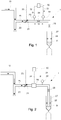
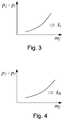
- the constants k t and k R are given by measurements performed in advance, see Figs. 3 and 4 , where the measured pressure difference ⁇ p is plotted for different air mass flows m f .
- the constant k t is used to determine the pressure drop from the first pressure gauge 22 to the tube 27 of packaging material.
- the pressures p 1 and p 2 are measured, and the difference ⁇ p is constantly monitored.
- the pressure p t inside the tube is then calculated, according to the above calculations, by the control unit 30. If the pressure p t deviates from predetermined limits, the air mass flow is controlled, either increased or decreased, such that the correct pressure p t is achieved inside the tube.
- the machine might need to be stopped, for a more detailed control. This can e.g. happen when the tube seal 26 is worn out, and needs to be replaced.
Landscapes
- Chemical & Material Sciences (AREA)
- Dispersion Chemistry (AREA)
- Engineering & Computer Science (AREA)
- Mechanical Engineering (AREA)
- Basic Packing Technique (AREA)
- Containers And Plastic Fillers For Packaging (AREA)
Description
- The present invention relates to a device and a method for monitoring and controlling the pressure at a downstream part of a pipe, and in particular for controlling the pressure at a downstream part of a pipe in a filling machine.
- In filling machines for liquid food packages, such as sold by Tetra Pak® under the name Tetra Pak A1, a web of packaging material is sterilized, and is subsequently formed into a tube. This tube is filled with liquid food continually, and the tube of packaging material is transversally sealed and cut such that separate packages with liquid food are formed. The liquid food is generally filled inside the tube of packaging material up to a certain height, such that a certain pressure is created during the forming and sealing of the packages. Normally, the pillar of liquid food is enough for having good package forming, but in certain instances an additional over-pressure is required. This is normally provided by connecting a tube system of pressurised sterile air to the filling pipe, providing an over-pressure inside the tube of packaging material, acting on the pillar of liquid food and being maintained by a tube seal, arranged inside the tube of packaging material and sealing against the internal pipes. However, the pressure above the liquid pillar is difficult to measure, and may fluctuate during production, for various reasons.
-
US 4 731 980 shows a known filling machine having a filling pipe supplying liquid product to the tube of packaging material. - It is hence an object of the present invention to mitigate this drawback. In a first aspect, the invention provides a system for accurately monitoring the pressure inside the tube of packaging material by utilizing a method according to
claim 1. - All features described in connection with any aspect of the invention can be used with any other aspect of the invention.
- The invention will be further described with reference to a preferred embodiment, as shown in the drawings in which:
-
Fig. 1 shows a schematic drawing of the system according to one embodiment of the invention, -
Fig. 2 shows a schematic drawing of an alternative embodiment of the invention, and -
Figs. 3-4 show graphs used for calculating constants used in the method of the invention. - The present invention will now be described with references to the drawings. In
Fig. 1 , a schematic representation of thedevice 1 is shown for carrying out the method according to the invention. Thedevice 1 comprises aninlet pipe 10, supplying the device with sterile, pressurized air from an undisclosed source, such as a tank or pump. A branch pipe 20 branches off from the main pipe, and is provided with acontrol valve 21. Thebranch pipe 20 is further provided with afirst pressure gauge 22 and asecond pressure gauge 23, being separated by a short distance along thebranch pipe 20. Thebranch pipe 20 is then directed inside atube 27 of packaging material. Thebranch pipe 20 is arranged either inside or outside the filling pipe (not shown) for the liquid food product. Atube seal 26 is provided outside thesecond pipe 20, for sealing against the supply pipes, i.e.second pipe 20 and filling pipe, and against the inside of thetube 27 of packaging material, which is already provided with a longitudinal sealing further upstream. Thetube 27 of packaging material is sealed longitudinally and transversally by devices normally present in filling machines for liquid food packages, but those devices are not a part of the invention. - A precision-made
restriction 24 is inserted between the first 22 and second 23 pressure gauges, having a diameter of 10 mm. The flow restriction from thefirst pressure gauge 22 to thetube 27 of packaging material is represented by asecond restriction 25. The actual restriction is caused by the pipe itself, and its corners etc. - A
control unit 30 is connected to thefirst pressure gauge 22 via afirst connection 31 and to thesecond pressure gauge 23 via asecond connection 32. The first 31 and second 32 connections send the pressure measurements to thecontrol unit 30, for calculations. The control unit is connected to thecontrol valve 21 via acontrol line 33. - In
Fig. 2 , an alternative embodiment is shown. Instead of thesecond pressure gauge 23, amass flow meter 28 of a known type is inserted. Thismass flow meter 28 may be a coriolis flow meter, a thermal mass flow meter, a pitot tube or similar. In this embodiment, the airmass flow meter 28 sends a signal relating to the air mass flow to thecontrol unit 30 via athird connection 34. - The function of the
device 1 will now be explained. The pressurized air from theinlet pipe 10 is directed through thesecond pipe 20 and through acontrol valve 21. The air mass flow through thesecond pipe 20 is denoted with mf, and it is constant throughout the pipe. The air flow through thesecond pipe 20 enters the tube of packaging material, and the air leaks through thetube seal 26. - The pressure inside the
second pipe 20 is measured by thepressure gauges packaging material tube 27, but it is difficult, if not impossible, to have a pressure gauge inside thetube 27 of packaging material, e.g. for hygienic reasons. Instead, the pressure is measured at an upstream location by afirst pressure gauge 22 and the pressure inside thetube 27 is the pressure at thefirst pressure gauge 22 minus the pressure drop occurring in the pipe due to the flow resistance of the air mass flow inside thepipe 20, from the location of thefirst pressure gauge 22. The flow resistance varies with the air flow, so this has to be established with calibrations in advance. Thecontrol unit 30 receives the measurements for the pressures (for the second embodiment the direct air mass flow), and calculates the pressure inside thetube 27 of packaging material. For moderate air flows, when the compressibility of the air is small, the following applies:

- The constants kt and kR are given by measurements performed in advance, see
Figs. 3 and 4 , where the measured pressure difference Δp is plotted for different air mass flows mf. The constant kt is used to determine the pressure drop from thefirst pressure gauge 22 to thetube 27 of packaging material. During operation of the filling machine, the pressures p1 and p2 are measured, and the difference Δp is constantly monitored. The pressure pt inside the tube is then calculated, according to the above calculations, by thecontrol unit 30. If the pressure pt deviates from predetermined limits, the air mass flow is controlled, either increased or decreased, such that the correct pressure pt is achieved inside the tube. Should the air mass flow need to be increased or decreased too much, the machine might need to be stopped, for a more detailed control. This can e.g. happen when thetube seal 26 is worn out, and needs to be replaced. In the embodiment where there is only thefirst pressure gauge 22, and the air flow is measured directly with themass flow meter 28, the pressure pt at thetube 27 of packaging material is calculated according to
- Whilst the invention has been described with reference to a preferred embodiment, it will be appreciated that various modifications are possible within the scope of the invention.
- In this specification, unless expressly otherwise indicated, the word 'or' is used in the sense of an operator that returns a true value when either or both of the stated conditions is met, as opposed to the operator 'exclusive or' which requires that only one of the conditions is met. The word 'comprising' is used in the sense of 'including' rather than in to mean 'consisting of'. All prior teachings acknowledged above are hereby incorporated by reference. No acknowledgement of any prior published document herein should be taken to be an admission or representation that the teaching thereof was common general knowledge in Australia or elsewhere at the date hereof.
Claims (8)
- Device (1) in a filling machine, said filling machine comprising a filling pipe for supplying liquid food to the tube (27) of packaging material, a pipe (20) for supplying pressurized sterile air to the tube (27) of packaging material, and a gasket (26) for sealing against the tube (27) of packaging material and any pipes (20) inside the tube (27), for creating an overpressure in said tube (27), the device (1) comprising a first pressure gauge (22) for measuring a first pressure (p1 ) inside the pipe (20) at a location upstream from the tube (27), means (22, 23; 28) for determining an air mass flow (mf ) in said pipe (20), and a control unit (30) for receiving the measured parameters (p1, mf ), said control unit (30) being adapted to calculate the pressure (pt ) in said tube (27) based on the air mass flow (mf ) and the first pressure (p1 ), according to a first pre-established relationship (R1).
- Device (1) according to claim 1, where the means (22, 23) for determining an air mass flow (mf ) further comprises a second pressure gauge (23) for measuring a second pressure (p2 ), and the pressure (pt ) at the tube (27) of packaging material is calculated by a control unit (30) based on the pressure difference (Δp) between the second pressure (p2 ) and the first pressure (p1 ), and on the first pressure (p1 ), according to a second pre-established relationship (R2).
- Device (1) according to claim 2, where a precision-made restriction (24) is located between the first pressure gauge (22) and the second pressure gauge (23), for obtaining accurate measurements of the pressure difference between said pressure gauges (22, 23).
- Device (1) according to any claim, wherein a control valve (21), being controlled by the control unit (30), is arranged in the pipe (20) for controlling the mass flow (mf ) of sterile air such that the pressure (pt ) inside said tube (27) of packaging material is controlled.
- Filling machine comprising a device (1) according to any of claims 1 to 4.
- Method of controlling a pressure in a tube (27) of packaging material in a filling machine, said filling machine comprising a filling pipe for supplying liquid food to the tube (27) of packaging material, a pipe (20) for supplying pressurized sterile air to the tube (27) of packaging material, and a gasket (26) for sealing against the tube (27) of packaging material and any pipes inside the tube (27), for creating an overpressure in said tube (27), said method comprising the steps:a) measuring a first pressure (p1 ) in the sterile air supply pipe (20), located upstream of the tube (27) of packaging material,b) measuring the air mass flow (mf ) in said pipe (20),c) calculating the pressure drop from the location of said upstream pressure (p1 ) to the tube, using the pressure (p1 ) and the mass flow (mf ), andd) calculating the pressure at said tube (27) of packaging material as the pressure at the location of the first pressure (p1 ) minus the pressure drop from that location to the tube (27) of packaging material.
- Method according to claim 6, wherein the step of measuring the air mass flow (mf ) in said pipe (20) comprises a step of measuring a second pressure (p2 ) at a location upstream from the location of said first pressure (p1 ), and using said pressure drop from the location of the second pressure (p2 ) to the location of the first pressure (p1 ) for determining the air mass flow, according to a third pre-established relationship (R3).
- Method according to any of claims 6 or 7, further comprising a step of:controlling the air mass flow, by a control valve (21), for controlling the pressure (pt ) inside the tube (27) of packaging material.
Applications Claiming Priority (2)
| Application Number | Priority Date | Filing Date | Title |
|---|---|---|---|
| SE1350680 | 2013-06-04 | ||
| PCT/EP2014/060044 WO2014195112A1 (en) | 2013-06-04 | 2014-05-16 | Device and method in a filling machine |
Publications (2)
| Publication Number | Publication Date |
|---|---|
| EP3003877A1 EP3003877A1 (en) | 2016-04-13 |
| EP3003877B1 true EP3003877B1 (en) | 2017-04-12 |
Family
ID=50732187
Family Applications (1)
| Application Number | Title | Priority Date | Filing Date |
|---|---|---|---|
| EP14724457.8A Active EP3003877B1 (en) | 2013-06-04 | 2014-05-16 | Device and method in a filling machine |
Country Status (5)
| Country | Link |
|---|---|
| US (1) | US10494125B2 (en) |
| EP (1) | EP3003877B1 (en) |
| JP (1) | JP6340417B2 (en) |
| CN (1) | CN105263808B (en) |
| WO (1) | WO2014195112A1 (en) |
Families Citing this family (7)
| Publication number | Priority date | Publication date | Assignee | Title |
|---|---|---|---|---|
| NL2018335B1 (en) * | 2017-02-08 | 2018-09-03 | Perfo Tec B V | Method and apparatus for packaging respiring produce |
| US10875675B2 (en) * | 2017-09-13 | 2020-12-29 | Tetra Laval Holdings & Finance S.A. | Packaging apparatus for forming sealed packages |
| ES2890403T3 (en) * | 2018-09-11 | 2022-01-19 | Tetra Laval Holdings & Finance | Packaging apparatus for forming sealed packages |
| WO2020108943A1 (en) * | 2018-11-26 | 2020-06-04 | Tetra Laval Holdings & Finance S.A. | A method and a packaging apparatus for forming sealed packages |
| WO2020108944A1 (en) * | 2018-11-26 | 2020-06-04 | Tetra Laval Holdings & Finance S.A. | A method and a packaging apparatus for forming sealed partially-filled packages |
| EP3656686B1 (en) * | 2018-11-26 | 2022-01-05 | Tetra Laval Holdings & Finance S.A. | A packaging apparatus for forming sealed packages |
| DE102019123460A1 (en) * | 2019-09-02 | 2021-03-04 | Khs Gmbh | Method for filling and closing containers |
Family Cites Families (77)
| Publication number | Priority date | Publication date | Assignee | Title |
|---|---|---|---|---|
| US2160367A (en) * | 1937-11-27 | 1939-05-30 | Stokes & Smith Co | Method of making sealed packages |
| US2618814A (en) * | 1948-08-13 | 1952-11-25 | James B Paton | Method of packaging comminuted materials in containers of extruded thermoplastic materials |
| US2687740A (en) * | 1951-05-23 | 1954-08-31 | Hermorion Ltd | Device for filling liquids into containers |
| CH399287A (en) * | 1962-04-12 | 1966-03-31 | Alpura Ag | Method and device for the sterile packaging of sterile consumables |
| GB1103760A (en) * | 1965-01-27 | 1968-02-21 | Tepar Ag | A method of establishing and maintaining asepsis in packaging machines and an apparatus for carrying out the method |
| SE331448B (en) * | 1966-06-30 | 1970-12-21 | Tetra Pak Ab | |
| US3520321A (en) * | 1967-12-20 | 1970-07-14 | Mojonnier Bros Co | Venting valve for a beverage filler |
| US3545983A (en) * | 1968-07-15 | 1970-12-08 | Fmc Corp | Method of deoxygenating and packaging of food products |
| US3664086A (en) * | 1969-12-29 | 1972-05-23 | Hayssen Mfg Co | Gas flushing system for vertical form, fill and seal machines |
| US3789888A (en) * | 1969-12-29 | 1974-02-05 | Hayssen Mfg Co | Gas flushing system for vertical form, fill and seal machines |
| US3665959A (en) * | 1971-03-12 | 1972-05-30 | Gaz De France | Pressure regulating and reducing gas-flow meter for industrial installations |
| DE2202292C3 (en) * | 1972-01-19 | 1979-05-10 | Holstein Und Kappert Gmbh, 4600 Dortmund | FüUorgan for counter pressure filling machines |
| US3970426A (en) * | 1974-03-18 | 1976-07-20 | Deering Milliken Research Corporation | Method and apparatus for the presterilization of packing machines |
| SE7513420L (en) * | 1975-11-28 | 1977-05-29 | Ziristor Ab | SET AND DEVICE FOR STERILIZING PACKAGING MATERIAL |
| US4127976A (en) * | 1977-08-24 | 1978-12-05 | Atlas Powder Company | Method and apparatus for making dual compartment containers |
| DE2931527A1 (en) * | 1978-09-29 | 1980-04-17 | Sig Schweiz Industrieges | DEVICE FOR PRODUCING AND FILLING HOSE BAGS |
| US4235265A (en) * | 1979-03-05 | 1980-11-25 | The Mead Corporation | Aseptic container filler apparatus |
| US4308710A (en) * | 1979-06-06 | 1982-01-05 | E. I. Du Pont De Nemours And Company | Process and apparatus for packaging |
| SE454167B (en) * | 1982-09-27 | 1988-04-11 | Tetra Pak Ab | SET AND DEVICE FOR MANUFACTURING PACKAGING CONTAINERS |
| GB2139994B (en) * | 1983-04-19 | 1986-08-13 | House Food Industrial Co | Sterilizing + filling apparatus |
| SE437136B (en) * | 1984-03-08 | 1985-02-11 | Tetra Pak Int | SET AND DEVICE FOR MANUFACTURING AND FILLING OF PACKAGING CONTAINERS |
| IT1180246B (en) * | 1984-12-28 | 1987-09-23 | Tetra Dev Co | ASEPTIC FILLING UNIT FOR PACKAGING MACHINES OF LONG PRESERVATION FLUID BEHAVIOR PRODUCTS |
| CH667246A5 (en) * | 1985-02-18 | 1988-09-30 | Ilapak Res & Dev Sa | VERTICAL TUBE MACHINE. |
| US4636391A (en) * | 1985-08-22 | 1987-01-13 | Patrick J. Furlong | Apparatus and method of forming a sterile product package |
| IT1188390B (en) * | 1986-02-14 | 1988-01-07 | Tetra Dev Co | METHOD AND COMPLEX IN PACKAGING MACHINES |
| US4731980A (en) * | 1986-12-17 | 1988-03-22 | International Paper Company | Apparatus for forming a tube from polyfoil web for high capacity aseptic form, fill, and seal machines |
| US4860804A (en) * | 1986-12-23 | 1989-08-29 | Mitsubishi Jukogyo Kabushiki Kaisha | Filled amount control system |
| BE1000670A5 (en) * | 1987-06-25 | 1989-03-07 | Baxter Travenol Lab | Device for filling a bag with an infusion liquid. |
| JPH0635921Y2 (en) * | 1987-11-20 | 1994-09-21 | 四国化工機株式会社 | Level controller for filling liquid level in packaging tube |
| JPH0610262Y2 (en) * | 1987-12-29 | 1994-03-16 | 四国化工機株式会社 | Hydrogen peroxide water spray device |
| JPH01182219A (en) * | 1988-01-08 | 1989-07-20 | Osaka Gas Co Ltd | Method of gas filling to container |
| US4821580A (en) * | 1988-01-27 | 1989-04-18 | Jorritsma Johannes N | Method and apparatus for calculating flow rates through a pumping station |
| DE3807046A1 (en) * | 1988-03-04 | 1989-10-12 | Seitz Enzinger Noll Masch | METHOD AND DEVICE FOR FILLING CARBONIC LIQUIDS, IN PARTICULAR DRINKS, UNDER BACK PRESSURE IN VESSELS OR THE LIKE. |
| DE4036290A1 (en) * | 1990-06-06 | 1991-12-12 | Kronseder Maschf Krones | METHOD AND DEVICE FOR STERILY FILLING BEVERAGE LIQUIDS |
| US5142846A (en) * | 1991-05-09 | 1992-09-01 | Gabilan Manufacturing, Inc. | Apparatus and method for bagging a product |
| US5361560A (en) * | 1992-10-13 | 1994-11-08 | Ralph Sandolo | Apparatus for flavoring and packaging coffee |
| DE69308807D1 (en) * | 1992-12-24 | 1997-04-17 | Ibaraki Seiki Machinery Co Ltd | Device for packaging objects in a vented state |
| IT1262305B (en) * | 1993-02-23 | 1996-06-19 | PROCESS AND PLANT FOR PACKAGING FLUID OR SEMI-FLUID PRODUCTS IN THERMOFORMABLE SYNTHETIC RESIN CONTAINERS. | |
| JP2759608B2 (en) * | 1993-04-28 | 1998-05-28 | 川澄化学工業株式会社 | Method and apparatus for manufacturing medical bags |
| IT1269723B (en) * | 1994-05-09 | 1997-04-15 | Tetra Brik Res Dev Spa | METHOD AND EQUIPMENT TO REGISTER A CONTENT LEVEL |
| US5533550A (en) * | 1994-09-30 | 1996-07-09 | Tetra Laval Holdings & Finance S.A. | Tank venting apparatus for a packaging machine |
| US5582217A (en) * | 1995-04-10 | 1996-12-10 | Servi-Tech, Inc. | Snift cam and methods |
| US5720326A (en) * | 1996-03-19 | 1998-02-24 | Tetra Laval Holdings & Finance S.A. | Method and apparatus for filling a container with reduced mixing of product and air |
| US5858040A (en) * | 1997-03-28 | 1999-01-12 | Tetra Laval Holdings & Finance, Sa | Filling machine having a microfiltrated clean air supply system |
| EP0882651B1 (en) * | 1997-06-04 | 2001-08-16 | Tetra Laval Holdings & Finance SA | Filling pipe for liquid-food packaging machines |
| DE19748805A1 (en) * | 1997-11-05 | 1999-05-06 | Rovema Gmbh | Packaging device |
| US6018932A (en) * | 1998-01-07 | 2000-02-01 | Premark Feg L.L.C. | Gas exchange apparatus |
| CN1202445A (en) * | 1998-06-30 | 1998-12-23 | 沈阳市自动化仪表研究所 | Sterile liquid filling machine |
| DE19840857A1 (en) * | 1998-09-08 | 2000-03-09 | Rovema Gmbh | Packaging arrangement, esp. for filling material into bags made from foil tube, has device that measures pressure in lower region of foil tube connected to measurement value indicator |
| JP4408489B2 (en) * | 1999-08-16 | 2010-02-03 | 株式会社イシダ | Bag making and packaging machine |
| JP4408510B2 (en) * | 1999-12-27 | 2010-02-03 | 株式会社イシダ | Bag making and packaging machine |
| US6645429B1 (en) * | 2000-01-11 | 2003-11-11 | The Quaker Oats Company | Sterilization system and method for food packaging |
| JP3866901B2 (en) * | 2000-03-24 | 2007-01-10 | 大成ラミック株式会社 | Package filling device |
| US6450215B1 (en) * | 2000-09-29 | 2002-09-17 | Charter Medical, Ltd. | Apparatus and method for filling bags |
| JP3560919B2 (en) * | 2001-02-06 | 2004-09-02 | オリヒロエンジニアリング株式会社 | Packaging bag manufacturing method and vertical bag making and filling machine |
| EP1334912B1 (en) * | 2002-02-08 | 2009-10-28 | Tetra Laval Holdings & Finance SA | Unit for sterilizing web material on a machine for packaging pourable food products |
| EP1334911B1 (en) * | 2002-02-08 | 2009-10-07 | Tetra Laval Holdings & Finance SA | Unit for sterilizing web material on a machine for packaging pourable food products |
| WO2004011334A1 (en) * | 2002-07-30 | 2004-02-05 | Ishida Co., Ltd. | Packing machine, packing method, and packing system |
| US6904737B2 (en) * | 2002-08-01 | 2005-06-14 | General Mills, Inc. | Dispensing apparatus and method of dispensing |
| JP4584595B2 (en) * | 2004-01-13 | 2010-11-24 | 四国化工機株式会社 | Sterilizer |
| ITBO20040534A1 (en) * | 2004-08-26 | 2004-11-26 | Gino Rapparini | PROCESS FOR ASEPTIC PACKAGING OF STERL LIQUIDS IN FLEXIBLE CONTAINERS |
| US7069964B1 (en) * | 2005-03-03 | 2006-07-04 | Shibuya Kogyo Co., Ltd. | Filler |
| US20060213153A1 (en) * | 2005-03-03 | 2006-09-28 | Sanfilippo James J | Device and system for modified atmosphere packaging |
| US20080000204A1 (en) * | 2006-06-28 | 2008-01-03 | S.C. Johnson Home Storage, Inc. | Vacuum sealer apparatus and a film cartridge for a vacuum sealer and a means of operating the vacuum sealer and the film cartridge |
| US7581427B2 (en) * | 2006-11-14 | 2009-09-01 | Mocon, Inc. | Workspace analyte sensing system and method using a fan to move samples from the workspace to the sensor |
| JP4959810B2 (en) * | 2007-01-23 | 2012-06-27 | シデル ホールディングス アンド テクノロジー エス. エー. | Filling equipment |
| BRPI0912328A2 (en) * | 2008-05-11 | 2017-06-13 | Tetra Laval Holding & Finance Sa | packing and loading machine. |
| US8938938B2 (en) * | 2008-05-11 | 2015-01-27 | Tetra Laval Holdings & Finance S.A. | Packaging and filling machine |
| CN102056806B (en) * | 2008-06-09 | 2012-07-04 | 利乐拉瓦尔集团及财务有限公司 | Packaging and filling apparatus |
| KR101936536B1 (en) * | 2009-06-10 | 2019-01-08 | 어드밴스드 테크놀러지 머티리얼즈, 인코포레이티드 | Fluid processing systems and methods |
| CN201530484U (en) * | 2009-09-29 | 2010-07-21 | 江西洪都航空工业集团有限责任公司 | Automatic control ventilation apparatus for storing and transporting box |
| DE102009045156A1 (en) * | 2009-09-30 | 2011-04-07 | Robert Bosch Gmbh | Apparatus and method for molding, filling and closing each having a pouring bag having |
| GB2475720A (en) * | 2009-11-27 | 2011-06-01 | Ashwell Packaging Supplies Ltd | Inner pack suspended within pressurized outer pack |
| CN102686483B (en) * | 2009-12-18 | 2014-06-11 | 利乐拉瓦尔集团及财务有限公司 | Filling assembly, gasket for use in the filling assembly, and a method for filling liquid |
| CN201726833U (en) * | 2010-06-25 | 2011-02-02 | 于亮 | Novel fluid ultra-high pressure processing device |
| DE102014104872A1 (en) * | 2014-04-04 | 2015-10-08 | Krones Ag | Method and device for filling a container to be filled with a filling product |
| DE102014107364A1 (en) * | 2014-05-26 | 2015-11-26 | Endress+Hauser Process Solutions Ag | Method for valve-controlled filling |
-
2014
- 2014-05-16 CN CN201480032240.8A patent/CN105263808B/en active Active
- 2014-05-16 WO PCT/EP2014/060044 patent/WO2014195112A1/en active Application Filing
- 2014-05-16 JP JP2016517211A patent/JP6340417B2/en active Active
- 2014-05-16 EP EP14724457.8A patent/EP3003877B1/en active Active
- 2014-05-16 US US14/895,780 patent/US10494125B2/en active Active
Non-Patent Citations (1)
| Title |
|---|
| None * |
Also Published As
| Publication number | Publication date |
|---|---|
| CN105263808A (en) | 2016-01-20 |
| EP3003877A1 (en) | 2016-04-13 |
| CN105263808B (en) | 2017-05-10 |
| JP6340417B2 (en) | 2018-06-06 |
| WO2014195112A1 (en) | 2014-12-11 |
| JP2016520490A (en) | 2016-07-14 |
| US20160122051A1 (en) | 2016-05-05 |
| US10494125B2 (en) | 2019-12-03 |
Similar Documents
| Publication | Publication Date | Title |
|---|---|---|
| EP3003877B1 (en) | Device and method in a filling machine | |
| EP2695846B1 (en) | Rotary-type filling machine and method for calculating filling quantity for rotary-type filling machine | |
| US9175997B2 (en) | Self-monitoring flow measuring arrangement and method for its operation | |
| HK1156101A1 (en) | Method for generating a diagnostic from a deviation of a flow meter parameter | |
| US20130146176A1 (en) | Gas supply system and correction method | |
| MX2015004905A (en) | Ultrasonic flow metering system with an upstream pressure transducer. | |
| DE102013106155A1 (en) | Measuring system with a pressure device and method for monitoring and / or checking such a pressure device | |
| CN101532897B (en) | Long distance slurry pipeline transportation pressure detection system and detection method | |
| US7878074B1 (en) | Eccentric load sensing device used to sense differential pressures | |
| CN102812344A (en) | Improvements in vibrating tube densitometers | |
| JP2016520490A5 (en) | ||
| CN103852121A (en) | Metering System and Method for Cryogenic Liquids | |
| WO2018083453A1 (en) | Improvements in or relating to the monitoring of fluid flow | |
| US9816846B2 (en) | Apparatus and method for determining a non-condensable gas parameter | |
| RU2015142447A (en) | REGULATING DEVICE (OPTIONS) FOR REGULATING PRESSURE WITH FILTER STATUS SENSORS | |
| US9244053B2 (en) | Apparatus for monitoring aeration in fluid of hydraulic circuit | |
| US10830681B2 (en) | Method and measuring apparatus for determining compressibility of a flowing fluid | |
| KR102094423B1 (en) | Volume change measuring device for repeated pressurized testing of high pressure container | |
| KR100930641B1 (en) | Hybrid-type multi-path ultrasonic flow meter | |
| JP2008058057A (en) | Ultrasonic flowmeter | |
| US20220136883A1 (en) | Fluid metering/monitoring system using vibration | |
| KR101340334B1 (en) | Establishment method of Standard Dynamic Pressure by using fluid | |
| EP2933612A1 (en) | Method of determining an internal volume of a filter or a bag device, computer program product and a testing apparatus for performing the method | |
| EP3048433A1 (en) | Tanker and method applying a detection device | |
| RU2013109629A (en) | METHOD FOR DETECTING OIL OR OIL PRODUCT FROM PIPELINE |
Legal Events
| Date | Code | Title | Description |
|---|---|---|---|
| PUAI | Public reference made under article 153(3) epc to a published international application that has entered the european phase |
Free format text: ORIGINAL CODE: 0009012 |
|
| 17P | Request for examination filed |
Effective date: 20160104 |
|
| AK | Designated contracting states |
Kind code of ref document: A1 Designated state(s): AL AT BE BG CH CY CZ DE DK EE ES FI FR GB GR HR HU IE IS IT LI LT LU LV MC MK MT NL NO PL PT RO RS SE SI SK SM TR |
|
| AX | Request for extension of the european patent |
Extension state: BA ME |
|
| DAX | Request for extension of the european patent (deleted) | ||
| GRAP | Despatch of communication of intention to grant a patent |
Free format text: ORIGINAL CODE: EPIDOSNIGR1 |
|
| INTG | Intention to grant announced |
Effective date: 20161124 |
|
| GRAS | Grant fee paid |
Free format text: ORIGINAL CODE: EPIDOSNIGR3 |
|
| GRAA | (expected) grant |
Free format text: ORIGINAL CODE: 0009210 |
|
| AK | Designated contracting states |
Kind code of ref document: B1 Designated state(s): AL AT BE BG CH CY CZ DE DK EE ES FI FR GB GR HR HU IE IS IT LI LT LU LV MC MK MT NL NO PL PT RO RS SE SI SK SM TR |
|
| REG | Reference to a national code |
Ref country code: GB Ref legal event code: FG4D |
|
| REG | Reference to a national code |
Ref country code: CH Ref legal event code: EP |
|
| REG | Reference to a national code |
Ref country code: IE Ref legal event code: FG4D |
|
| REG | Reference to a national code |
Ref country code: AT Ref legal event code: REF Ref document number: 883595 Country of ref document: AT Kind code of ref document: T Effective date: 20170515 |
|
| REG | Reference to a national code |
Ref country code: DE Ref legal event code: R096 Ref document number: 602014008566 Country of ref document: DE |
|
| REG | Reference to a national code |
Ref country code: FR Ref legal event code: PLFP Year of fee payment: 4 |
|
| REG | Reference to a national code |
Ref country code: NL Ref legal event code: MP Effective date: 20170412 |
|
| REG | Reference to a national code |
Ref country code: LT Ref legal event code: MG4D |
|
| REG | Reference to a national code |
Ref country code: AT Ref legal event code: MK05 Ref document number: 883595 Country of ref document: AT Kind code of ref document: T Effective date: 20170412 |
|
| PG25 | Lapsed in a contracting state [announced via postgrant information from national office to epo] |
Ref country code: NL Free format text: LAPSE BECAUSE OF FAILURE TO SUBMIT A TRANSLATION OF THE DESCRIPTION OR TO PAY THE FEE WITHIN THE PRESCRIBED TIME-LIMIT Effective date: 20170412 |
|
| PG25 | Lapsed in a contracting state [announced via postgrant information from national office to epo] |
Ref country code: FI Free format text: LAPSE BECAUSE OF FAILURE TO SUBMIT A TRANSLATION OF THE DESCRIPTION OR TO PAY THE FEE WITHIN THE PRESCRIBED TIME-LIMIT Effective date: 20170412 Ref country code: NO Free format text: LAPSE BECAUSE OF FAILURE TO SUBMIT A TRANSLATION OF THE DESCRIPTION OR TO PAY THE FEE WITHIN THE PRESCRIBED TIME-LIMIT Effective date: 20170712 Ref country code: ES Free format text: LAPSE BECAUSE OF FAILURE TO SUBMIT A TRANSLATION OF THE DESCRIPTION OR TO PAY THE FEE WITHIN THE PRESCRIBED TIME-LIMIT Effective date: 20170412 Ref country code: HR Free format text: LAPSE BECAUSE OF FAILURE TO SUBMIT A TRANSLATION OF THE DESCRIPTION OR TO PAY THE FEE WITHIN THE PRESCRIBED TIME-LIMIT Effective date: 20170412 Ref country code: GR Free format text: LAPSE BECAUSE OF FAILURE TO SUBMIT A TRANSLATION OF THE DESCRIPTION OR TO PAY THE FEE WITHIN THE PRESCRIBED TIME-LIMIT Effective date: 20170713 Ref country code: LT Free format text: LAPSE BECAUSE OF FAILURE TO SUBMIT A TRANSLATION OF THE DESCRIPTION OR TO PAY THE FEE WITHIN THE PRESCRIBED TIME-LIMIT Effective date: 20170412 Ref country code: AT Free format text: LAPSE BECAUSE OF FAILURE TO SUBMIT A TRANSLATION OF THE DESCRIPTION OR TO PAY THE FEE WITHIN THE PRESCRIBED TIME-LIMIT Effective date: 20170412 |
|
| PG25 | Lapsed in a contracting state [announced via postgrant information from national office to epo] |
Ref country code: LV Free format text: LAPSE BECAUSE OF FAILURE TO SUBMIT A TRANSLATION OF THE DESCRIPTION OR TO PAY THE FEE WITHIN THE PRESCRIBED TIME-LIMIT Effective date: 20170412 Ref country code: IS Free format text: LAPSE BECAUSE OF FAILURE TO SUBMIT A TRANSLATION OF THE DESCRIPTION OR TO PAY THE FEE WITHIN THE PRESCRIBED TIME-LIMIT Effective date: 20170812 Ref country code: RS Free format text: LAPSE BECAUSE OF FAILURE TO SUBMIT A TRANSLATION OF THE DESCRIPTION OR TO PAY THE FEE WITHIN THE PRESCRIBED TIME-LIMIT Effective date: 20170412 Ref country code: PL Free format text: LAPSE BECAUSE OF FAILURE TO SUBMIT A TRANSLATION OF THE DESCRIPTION OR TO PAY THE FEE WITHIN THE PRESCRIBED TIME-LIMIT Effective date: 20170412 Ref country code: BG Free format text: LAPSE BECAUSE OF FAILURE TO SUBMIT A TRANSLATION OF THE DESCRIPTION OR TO PAY THE FEE WITHIN THE PRESCRIBED TIME-LIMIT Effective date: 20170712 Ref country code: SE Free format text: LAPSE BECAUSE OF FAILURE TO SUBMIT A TRANSLATION OF THE DESCRIPTION OR TO PAY THE FEE WITHIN THE PRESCRIBED TIME-LIMIT Effective date: 20170412 |
|
| REG | Reference to a national code |
Ref country code: CH Ref legal event code: PL |
|
| REG | Reference to a national code |
Ref country code: DE Ref legal event code: R097 Ref document number: 602014008566 Country of ref document: DE |
|
| PG25 | Lapsed in a contracting state [announced via postgrant information from national office to epo] |
Ref country code: DK Free format text: LAPSE BECAUSE OF FAILURE TO SUBMIT A TRANSLATION OF THE DESCRIPTION OR TO PAY THE FEE WITHIN THE PRESCRIBED TIME-LIMIT Effective date: 20170412 Ref country code: EE Free format text: LAPSE BECAUSE OF FAILURE TO SUBMIT A TRANSLATION OF THE DESCRIPTION OR TO PAY THE FEE WITHIN THE PRESCRIBED TIME-LIMIT Effective date: 20170412 Ref country code: CZ Free format text: LAPSE BECAUSE OF FAILURE TO SUBMIT A TRANSLATION OF THE DESCRIPTION OR TO PAY THE FEE WITHIN THE PRESCRIBED TIME-LIMIT Effective date: 20170412 Ref country code: MC Free format text: LAPSE BECAUSE OF FAILURE TO SUBMIT A TRANSLATION OF THE DESCRIPTION OR TO PAY THE FEE WITHIN THE PRESCRIBED TIME-LIMIT Effective date: 20170412 Ref country code: RO Free format text: LAPSE BECAUSE OF FAILURE TO SUBMIT A TRANSLATION OF THE DESCRIPTION OR TO PAY THE FEE WITHIN THE PRESCRIBED TIME-LIMIT Effective date: 20170412 Ref country code: SK Free format text: LAPSE BECAUSE OF FAILURE TO SUBMIT A TRANSLATION OF THE DESCRIPTION OR TO PAY THE FEE WITHIN THE PRESCRIBED TIME-LIMIT Effective date: 20170412 |
|
| PLBE | No opposition filed within time limit |
Free format text: ORIGINAL CODE: 0009261 |
|
| STAA | Information on the status of an ep patent application or granted ep patent |
Free format text: STATUS: NO OPPOSITION FILED WITHIN TIME LIMIT |
|
| REG | Reference to a national code |
Ref country code: IE Ref legal event code: MM4A |
|
| PG25 | Lapsed in a contracting state [announced via postgrant information from national office to epo] |
Ref country code: LI Free format text: LAPSE BECAUSE OF NON-PAYMENT OF DUE FEES Effective date: 20170531 Ref country code: SM Free format text: LAPSE BECAUSE OF FAILURE TO SUBMIT A TRANSLATION OF THE DESCRIPTION OR TO PAY THE FEE WITHIN THE PRESCRIBED TIME-LIMIT Effective date: 20170412 Ref country code: CH Free format text: LAPSE BECAUSE OF NON-PAYMENT OF DUE FEES Effective date: 20170531 |
|
| 26N | No opposition filed |
Effective date: 20180115 |
|
| PG25 | Lapsed in a contracting state [announced via postgrant information from national office to epo] |
Ref country code: LU Free format text: LAPSE BECAUSE OF NON-PAYMENT OF DUE FEES Effective date: 20170516 |
|
| REG | Reference to a national code |
Ref country code: FR Ref legal event code: PLFP Year of fee payment: 5 |
|
| REG | Reference to a national code |
Ref country code: BE Ref legal event code: MM Effective date: 20170531 |
|
| PG25 | Lapsed in a contracting state [announced via postgrant information from national office to epo] |
Ref country code: IE Free format text: LAPSE BECAUSE OF NON-PAYMENT OF DUE FEES Effective date: 20170516 |
|
| PG25 | Lapsed in a contracting state [announced via postgrant information from national office to epo] |
Ref country code: SI Free format text: LAPSE BECAUSE OF FAILURE TO SUBMIT A TRANSLATION OF THE DESCRIPTION OR TO PAY THE FEE WITHIN THE PRESCRIBED TIME-LIMIT Effective date: 20170412 |
|
| PG25 | Lapsed in a contracting state [announced via postgrant information from national office to epo] |
Ref country code: BE Free format text: LAPSE BECAUSE OF NON-PAYMENT OF DUE FEES Effective date: 20170531 |
|
| PGFP | Annual fee paid to national office [announced via postgrant information from national office to epo] |
Ref country code: FR Payment date: 20180411 Year of fee payment: 5 |
|
| PG25 | Lapsed in a contracting state [announced via postgrant information from national office to epo] |
Ref country code: MT Free format text: LAPSE BECAUSE OF NON-PAYMENT OF DUE FEES Effective date: 20170516 |
|
| GBPC | Gb: european patent ceased through non-payment of renewal fee |
Effective date: 20180516 |
|
| PG25 | Lapsed in a contracting state [announced via postgrant information from national office to epo] |
Ref country code: GB Free format text: LAPSE BECAUSE OF NON-PAYMENT OF DUE FEES Effective date: 20180516 |
|
| PG25 | Lapsed in a contracting state [announced via postgrant information from national office to epo] |
Ref country code: HU Free format text: LAPSE BECAUSE OF FAILURE TO SUBMIT A TRANSLATION OF THE DESCRIPTION OR TO PAY THE FEE WITHIN THE PRESCRIBED TIME-LIMIT; INVALID AB INITIO Effective date: 20140516 |
|
| PG25 | Lapsed in a contracting state [announced via postgrant information from national office to epo] |
Ref country code: CY Free format text: LAPSE BECAUSE OF FAILURE TO SUBMIT A TRANSLATION OF THE DESCRIPTION OR TO PAY THE FEE WITHIN THE PRESCRIBED TIME-LIMIT Effective date: 20170412 |
|
| PG25 | Lapsed in a contracting state [announced via postgrant information from national office to epo] |
Ref country code: MK Free format text: LAPSE BECAUSE OF FAILURE TO SUBMIT A TRANSLATION OF THE DESCRIPTION OR TO PAY THE FEE WITHIN THE PRESCRIBED TIME-LIMIT Effective date: 20170412 |
|
| PG25 | Lapsed in a contracting state [announced via postgrant information from national office to epo] |
Ref country code: TR Free format text: LAPSE BECAUSE OF FAILURE TO SUBMIT A TRANSLATION OF THE DESCRIPTION OR TO PAY THE FEE WITHIN THE PRESCRIBED TIME-LIMIT Effective date: 20170412 |
|
| PG25 | Lapsed in a contracting state [announced via postgrant information from national office to epo] |
Ref country code: PT Free format text: LAPSE BECAUSE OF FAILURE TO SUBMIT A TRANSLATION OF THE DESCRIPTION OR TO PAY THE FEE WITHIN THE PRESCRIBED TIME-LIMIT Effective date: 20170412 |
|
| PG25 | Lapsed in a contracting state [announced via postgrant information from national office to epo] |
Ref country code: FR Free format text: LAPSE BECAUSE OF NON-PAYMENT OF DUE FEES Effective date: 20190531 |
|
| PG25 | Lapsed in a contracting state [announced via postgrant information from national office to epo] |
Ref country code: AL Free format text: LAPSE BECAUSE OF FAILURE TO SUBMIT A TRANSLATION OF THE DESCRIPTION OR TO PAY THE FEE WITHIN THE PRESCRIBED TIME-LIMIT Effective date: 20170412 |
|
| P01 | Opt-out of the competence of the unified patent court (upc) registered |
Effective date: 20230426 |
|
| PGFP | Annual fee paid to national office [announced via postgrant information from national office to epo] |
Ref country code: IT Payment date: 20230525 Year of fee payment: 10 Ref country code: DE Payment date: 20230530 Year of fee payment: 10 |