EP1077175A2 - Teleskopische Gabelanordnung - Google Patents
Teleskopische Gabelanordnung Download PDFInfo
- Publication number
- EP1077175A2 EP1077175A2 EP00850123A EP00850123A EP1077175A2 EP 1077175 A2 EP1077175 A2 EP 1077175A2 EP 00850123 A EP00850123 A EP 00850123A EP 00850123 A EP00850123 A EP 00850123A EP 1077175 A2 EP1077175 A2 EP 1077175A2
- Authority
- EP
- European Patent Office
- Prior art keywords
- piston
- leg
- return
- arrangement according
- compression
- Prior art date
- Legal status (The legal status is an assumption and is not a legal conclusion. Google has not performed a legal analysis and makes no representation as to the accuracy of the status listed.)
- Granted
Links
Images


Classifications
-
- B—PERFORMING OPERATIONS; TRANSPORTING
- B62—LAND VEHICLES FOR TRAVELLING OTHERWISE THAN ON RAILS
- B62K—CYCLES; CYCLE FRAMES; CYCLE STEERING DEVICES; RIDER-OPERATED TERMINAL CONTROLS SPECIALLY ADAPTED FOR CYCLES; CYCLE AXLE SUSPENSIONS; CYCLE SIDE-CARS, FORECARS, OR THE LIKE
- B62K25/00—Axle suspensions
- B62K25/04—Axle suspensions for mounting axles resiliently on cycle frame or fork
- B62K25/06—Axle suspensions for mounting axles resiliently on cycle frame or fork with telescopic fork, e.g. including auxiliary rocking arms
- B62K25/08—Axle suspensions for mounting axles resiliently on cycle frame or fork with telescopic fork, e.g. including auxiliary rocking arms for front wheel
-
- F—MECHANICAL ENGINEERING; LIGHTING; HEATING; WEAPONS; BLASTING
- F16—ENGINEERING ELEMENTS AND UNITS; GENERAL MEASURES FOR PRODUCING AND MAINTAINING EFFECTIVE FUNCTIONING OF MACHINES OR INSTALLATIONS; THERMAL INSULATION IN GENERAL
- F16F—SPRINGS; SHOCK-ABSORBERS; MEANS FOR DAMPING VIBRATION
- F16F9/00—Springs, vibration-dampers, shock-absorbers, or similarly-constructed movement-dampers using a fluid or the equivalent as damping medium
- F16F9/32—Details
- F16F9/44—Means on or in the damper for manual or non-automatic adjustment; such means combined with temperature correction
- F16F9/46—Means on or in the damper for manual or non-automatic adjustment; such means combined with temperature correction allowing control from a distance, i.e. location of means for control input being remote from site of valves, e.g. on damper external wall
- F16F9/466—Throttling control, i.e. regulation of flow passage geometry
Definitions
- the present invention relates to a telescopic fork arrangement for the front wheel of vehicles, in particular of motorcycles.
- the arrangement comprises at least two telescopic legs, each having telescopically arranged tubes and, arranged in these, piston and piston-rod arrangements operating in a working medium which can be of a type known per se, preferably in the form of hydraulic oil.
- each leg is made up of telescopically arranged tubes and where a piston rod is fixed at one end of the leg and extends inside one or more outer tubes and supports, at its other end, a piston which is intended to be displaceable in an inner tube.
- a front wheel is mounted on the said outer tube at the end of the leg, and the inner tube is mounted on a bearing part which in turn is fixed in a chassis of the vehicle/motorcycle.
- the structure of the leg and tube arrangement can vary.
- a characteristic of telescopic legs of the type in question is also that a mechanical main spring is arranged in or near the tubes.
- a working medium is arranged inside the tube in question.
- the piston operates in this working medium to effect the damping function.
- a channel system is usually provided outside the piston in the tube arrangement, which channel system permits delivery and return of the working medium as the piston moves as a function of spring movements.
- the channel system is routed through a control valve arrangement, by means of which the damping characteristic for the leg can be determined.
- the control valve arrangement can in this case be designed for adjusting the damping characteristics from outside using manually activated members.
- the channel system also allows medium to appear on both sides of the piston and for it to be exposed to atmospheric pressure at the upper side of the piston.
- the effects of cavitation and foam formation mean that there is no damping, or very poor damping, at high frequencies, for example frequencies of between 15 and 25 Hz, which can arise from tyre vibrations, driving on certain road surfaces, etc.
- high frequencies for example frequencies of between 15 and 25 Hz, which can arise from tyre vibrations, driving on certain road surfaces, etc.
- the invention aims to solve this problem, among others.
- the invention is based on the recognition that advantages are to be gained in this connection from using a pressurized working medium space, and that there is a need to be able to provide such a space which can function efficiently in different contexts for specialized and standard motorcycles.
- the invention solves this problem too.
- a pressurized system means that friction caused by piston rod seal or piston rod seals increases, which in turn has placed demands on the piston rod diameter having to be reduced. Since the surface area of the piston rod has hitherto constituted the factor for displacement upon movement of the piston, this has meant that the displacement has reduced upon each movement. This in turn has meant that the piston/piston-rod had to execute a relatively long movement on each damping, which resulted in an adverse, substantial hysteresis function and failed damping effect at high-frequency movements.
- the invention solves this problem too and allows the disadvantage of increased friction on account of pressurized working medium to be counteracted by great displacement with relatively small piston-rod and piston movements.
- a first telescopic leg hereinafter called the compression leg
- a second telescopic leg hereinafter called the return leg
- the return leg performs a damping function essentially only during its return movement. This means that the return leg does not perform or does not effect any real damping during its return movement.
- At least one of the said compression or return legs is connected to a pressure chamber unit which, in a closed system for the working medium, formed with the respective leg in question, keeps this working medium pressurized, and that a piston in the piston/piston-rod arrangement is provided with or cooperates with one or more members which perform or determine respective damping functions.
- the displacement in the pressurized medium upon each piston and piston-rod movement is dependent on or related to the surface areas of the piston.
- the increased friction caused by the pressurized medium (compared to the case with non-pressurized medium) is compensated by increased displacement generated by the piston/piston area instead of the piston rod/piston-rod area.
- the compression leg can comprise a check valve unit for a bleed adjustment function.
- the check valve can be activated for or at low media speeds in the bleed adjustment function on the compression stroke.
- the piston of the compression leg can in this case have, on its upper side, first media-activating members, preferably in the form of first shims, which it is particularly advantageous to use in this context.
- the member or the first shims have a stiff character, permitting media passage at high speeds on the compression stroke.
- the piston in question also has a first check valve function, preferably obtained with the aid of second shims arranged on the underside of the piston. The said first check valve function opens for media at low pressure on the return stroke of the compression leg.
- the first check valve function/the second shims are of weak character, and the said stiff and weak characters of the first and second shims are chosen to provide a marked difference in damping between the compression stroke and return stroke of the compression leg. This marked difference permits simplified adjustability for low-speed compression damping.
- the said check valve unit prevents media passage in the bleed adjustment function on the return stroke of the compression leg.
- the return leg comprises a bleed adjustment function permitting media passage at low media speeds on the return stroke of the return leg.
- the piston of the return leg has, on its underside, second media-activating members, preferably third shims which are of stiff character in order to permit media at high speeds on the return stroke.
- the last-mentioned piston has a second check valve function, preferably in the form of fourth shims arranged on the upper side of the piston and arranged to open for media at low pressure on the compression stroke of the return leg.
- the said second check valve function/fourth shims are of weak character.
- the stiff and weak characters of the third and fourth shims (the second check valve function) provide a marked difference in damping between the return stroke and compression stroke of the return leg. The said marked difference is chosen to facilitate adjustment of the low-speed return damping from outside by means of manually activated members.
- the bleed adjustment function allows a negligible part of the medium to pass on the compression stroke of the return leg.
- the piston of the compression leg consists of parts which can be joined together and comprise a first piston body part with axially extending through-holes. Also included are first and second shims which can be applied directly on the ends of the piston body part, and a combined connection and bearing part for the piston body part and a first bearing housing for internal bearing of front parts of a first element effecting the bleed adjustment function.
- the piston of the return leg consists of parts which can be joined together and comprise a second piston body part with axially extending through-holes, third and fourth shims which can be applied directly on the ends of the piston body part, and a second combined connection and bearing part for, inter alia, internal bearing of front parts of a second element effecting the bleed adjustment function.
- the first and second bearing parts extend a distance into an axial central recess in each of the first and second piston body parts.
- the compression and return legs can effect damping of high frequencies, for example frequencies of between 15 and 25 Hz caused, for example, by vibrations from tyres, road surface, etc.
- Each leg is connected to an accumulator unit which is held in the chamber and which operates with gas/nitrogen gas and separator piston between the working medium and the gas/nitrogen gas.
- a control valve is preferably arranged between the spaces for the working medium and the gas/separator piston.
- the said bleed function or bleed functions can be adjusted from one of the ends of the legs by means of manually activated members which mean that the adjustment can be effected from the outside.
- the control valve can be controlled from a unit containing the control valve for adjustment of the compression against which the piston/ piston-rod arrangement presses. The response of the damping function is accelerated by the fact that the displacement and force thereof are related to or applied to the piston/piston area.
- the proposed arrangement has a relatively simple structure and makes it possible to counter the effects of high frictional forces arising in the arrangement as a result of pressurized working medium being used.
- the structure is extremely simple, and structural components which are known per se in this technical field can largely be used.
- the arrangement can be fitted on special and standard motorcycles and could conceivably be used on, for example, three-wheeled vehicles.
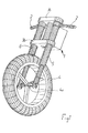
- FIG. 1 parts of a motorcycle (e.g. for road racing) are represented by way of a symbolically depicted chassis 1, handle-bars 2 and telescopic fork arrangement 3 supporting a front wheel 4 of the motorcycle.
- the arrangement 3 comprises two telescopic legs 5 and 6 which are outwardly designed and secured to the chassis in a manner known per se.
- one leg for example leg 5, provides damping essentially only in its compression direction, i.e. no real damping takes place in the return direction of the leg
- the second leg for example leg 6, provides damping essentially only in the return direction, i.e. no damping takes place in the compression direction of the leg.
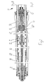
- Figures 2 and 3 show, when laid side by side, the basic structure of the respective leg 5 or 6.
- the leg construction has been supplemented by first components, specified below, in order to form a compression leg, i.e. the leg 5 in Figure 1.
- first components specified below
- second components specified below
- a return leg is obtained, i.e. the leg 6 according to Figure 1.
- the basic structure is to a large extent designed in a manner known per se using components known per se and it will therefore only be described where relevant to the invention.
- the basic design comprises, inter alia, an outer tube 7 and an inner tube 8 which is mounted so as to be longitudinally displaceable in the outer tube 7.
- a piston rod 10 is secured to the first end 9 of the leg, and a piston 12 or piston arrangement is secured to the free end 11 of the piston rod.
- the rod and the piston can be considered as forming parts of a piston/piston rod arrangement 10, 12.
- the piston rod extends centrally inside the outer tube 7 and centrally into the inner tube 8 in which there is arranged a further inner tube 13, inside which the piston 12 works.
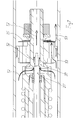
- the movement of the inner tube 13 is coordinated with the movement of the tube 8, and both tubes 8 and 13 are connected to an attachment point 14 ( Figure 3), by means of which the wheel 4 (see Figure 1) is mounted in the leg in a known manner in a bearing recess 14a.
- a spring 15 is arranged inside the tube 8.
- the piston rod extends inside the said spring 15, which at one end bears against a tubular stop 16 anchored in the leg end 9.
- the piston 12 works in a space 17 in the tube 13, and the piston rod is also mounted so as to be longitudinally displaceable in a bushing 19 which is secured in the inner wall of the tube 13.
- the piston rod 10 is sealed with respect to the bushing 19 via one or more sealing members 20.
- the spring 15 bears against the underside of the tube 13 against a flange 21 which can slide along the inner surface of the tube 8.
- the spring 15 thus forms a return spring for the inner tube 8 (and the tube 13) and seeks to push the inner tube out of the outer tube (towards the right in the figure).
- the downward spring movement of the inner tube in the outer tube thus takes place counter to the action of the said spring 15.
- the outer tube is assigned a pressure chamber unit 22.
- the pressure chamber unit can be of a type known per se and works with gas/nitrogen gas in a space 23 and a displaceable separator piston 24.
- a control valve unit 25 Arranged between the space 17 and the chamber 22 there is a control valve unit 25 which can be adjusted from outside by means of manual adjustment members accessible from the outside.
- the control valve 25 is of a known type used in the range from ⁇ hlins Racing®.
- the control valve comprises an adjusting screw 26 by means of which bleed through the valve is set, and piston with main passage(s) for the medium between the upper side and underside of the piston and shims and valve functions arranged at the passage(s).
- the control valve is incorporated as a damping member in accordance with the above, and each leg has its pressure chamber unit with control valve which effects its damping function essentially only in one direction.
- the space 17 is connected to a space 27 via a channel 28 and the control valve 25 allows working media passage depending on its setting and depending on movements in or on the piston 12.
- the separator piston 24 separates the gas and working media in a manner known per se.
- the arrangement means that a closed system is provided for the working medium and that this is at all times pressurized with the pressure chamber both on compression and return. No cavitation and foaming phenomenon can thus occur.
- the overpressure of the gas/nitrogen gas can be selected at about 6 bar.
- an elongate element (rod) 29 Arranged inside the piston rod 10 there is an elongate element (rod) 29 which takes part in the bleed adjustment function and which extends from the said end 9 to the piston arrangement 10.
- the element can be adjusted from the outside and can be displaced relative to a seat on the piston in order to function as bleed.
- the leg end 9 is situated at/secured to the chassis and the bleed is thus adjusted from above.
- the bleed function seat is indicated by 30.
- the element and seat functions 29, 30 can be designed and constructed in a manner known per se, and it will simply be noted here that the element 29 is arranged so as to be longitudinally displaceable relative to the seat depending on manual activation of the leg end 9 of the element.
- the bleed function can thus be increased or decreased.
- the components constituting a compression leg comprise a piston rod part 31 with seal 32 and axial through-holes 32, 33, 34, 35. Also included are first shims or shim stack 36 which is/are extremely stiff and second shims/shim stack 37 which is/are extremely weak. Each shim bears directly against the respective end of the piston rod part.
- a combined connection and bearing part is indicated by 38.
- the part is designed with the seat 30 and a recess 39 and bears a check valve unit 40.
- the part 38 has a bearing housing (or bearing housing part) 38a for bearing the front parts of the element 29.
- a check valve arrangement 41 in the form of a spring washer is also included.
- the part 38 also has a bearing recess 42 for the front portion of the piston rod 10, and between the piston rod 10 and the element 29 there is a slide bearing 43 for facilitating the rotation during the longitudinal displacement of the element relative to the piston rod upon setting of the bleed function.
- the part 38 is joined to the piston rod, for example by means of a threaded connection at or in the recess 42.
- spacer members 44 and 45 between the shims/shim stacks and the check valve unit 40, and a securing device 46 which is screwed securely to the end of the part 38.
- an impact-damping spring 47 (so-called top-out) arranged on the rear portion of the part 38.
- a damping device made of elastic material is arranged on parts of the piston rod below the piston in order to prevent metallic impact in the extended position.
- Figure 4 shows the passage of the media flow through the piston arrangement on the compression stroke of the compression leg.
- a media flow 48 can pass from the underside of the piston, bleed function 29, 30, radial recesses in the unit 38 and past the check valve 41 which is opened by the flow in question counter to the action of a spring (washer) 41 on the upper side of the piston.
- a direct media passage 49 is also established at the shim/shim stack 36 between the upper side and underside of the piston.
- Figure 5 shows the media flow on the return stroke of the compression leg when the medium passes from the upper side 12a of the piston 12 to its underside 12b.
- the media flow passes the member 37 which works in principle with a check valve function and which, in the illustrative embodiment, preferably consists of one or more shims.
- Figures 6 and 7 show the basic design of a leg according to Figures 2 and 3 supplemented with a second component set, giving the basic design the character of a return leg.
- the second component set has the same structure as the first component set, but with the difference that the check valve arrangement 40 according to Figure 4 is omitted in this case, i.e. the second component set is of simpler construction than the first one.
- the shim stacks 36' and 37' on the underside and upper side of the piston 12' have in principle changed places with the shim stacks 36 and 37 of the compression leg, i.e. the weaker shims operating with an almost purely check valve function are located on the upper side of the piston 12' and the stiff shims operating with a damping function are arranged on the underside of the piston.
- Figure 6 shows a media flow 51 directly between the underside and upper side of the piston via the check valve function 37' during the compression stroke of the return leg. No damping or very little damping is effected during the compression stroke by virtue of the check valve function and the fact that only a negligible amount of media can pass the rear wall and radial recesses (see above) of the bleed function in part 38'.
- the functions and structures of the various parts will be evident in this context.
- Figure 7 shows the media passage between the upper side and underside of the piston on the return stroke of the return leg when a damping function is to be exerted by the leg.
- a media passage 52 via the bleed function 29', 30'.
- a media passage is also established via the shims/shim stack 36' which exerts a damping function on the said return stroke.
- Shims are used preferably in the check valve functions in accordance with the above since they are quick and do not need to operate with distinctive positions. By means of the above, it is easy to adjust the low-speed compression or low-speed return damping from outside, directly on the main piston.
- the weak and stiff functions of the piston shims provide marked differences in the compression and return legs, which fact facilitates the adjustments of the low-speed compression and low-speed return damping from outside.
- the invention is not limited to the above illustrative embodiment, and instead it can be modified within the scope of the attached patent claims and the inventive concept.
- the control valve unit 25 used in the illustrative embodiment could in principle be omitted, although it has been found that it provided an accelerating effect in the telescopic leg arrangement.
- the valve used has the designation R-1565, which is a valve included in the range according to the above.
- the control valve unit is of the type which goes by the name of compression valve, i.e. it effects a certain damping upon the compression stroke. This means that a slight damping is also obtained from the valve on the compression stroke of the return leg.
Landscapes
- Engineering & Computer Science (AREA)
- Mechanical Engineering (AREA)
- General Engineering & Computer Science (AREA)
- Fluid-Damping Devices (AREA)
- Axle Suspensions And Sidecars For Cycles (AREA)
- Forklifts And Lifting Vehicles (AREA)
- Professional, Industrial, Or Sporting Protective Garments (AREA)
Applications Claiming Priority (2)
| Application Number | Priority Date | Filing Date | Title |
|---|---|---|---|
| SE9902944A SE514755C2 (sv) | 1999-08-19 | 1999-08-19 | Teleskopgaffelarrangemang |
| SE9902944 | 1999-08-19 |
Publications (3)
| Publication Number | Publication Date |
|---|---|
| EP1077175A2 true EP1077175A2 (de) | 2001-02-21 |
| EP1077175A3 EP1077175A3 (de) | 2002-05-29 |
| EP1077175B1 EP1077175B1 (de) | 2004-04-21 |
Family
ID=20416702
Family Applications (1)
| Application Number | Title | Priority Date | Filing Date |
|---|---|---|---|
| EP00850123A Expired - Lifetime EP1077175B1 (de) | 1999-08-19 | 2000-07-06 | Teleskopische Gabelanordnung |
Country Status (5)
| Country | Link |
|---|---|
| EP (1) | EP1077175B1 (de) |
| JP (1) | JP4375892B2 (de) |
| AT (1) | ATE264782T1 (de) |
| DE (1) | DE60009993T2 (de) |
| SE (1) | SE514755C2 (de) |
Cited By (3)
| Publication number | Priority date | Publication date | Assignee | Title |
|---|---|---|---|---|
| EP1876090A1 (de) | 2006-07-07 | 2008-01-09 | Yamaha Hatsudoki Kabushiki Kaisha | Hydraulischer Stoßdämpfer und Motorrad |
| US20100294606A1 (en) * | 2003-12-15 | 2010-11-25 | Showa Corporation | Hydraulic shock absorbing apparatus of vehicle |
| JP2012202427A (ja) * | 2011-03-24 | 2012-10-22 | Kyb Co Ltd | フロントフォーク |
Families Citing this family (3)
| Publication number | Priority date | Publication date | Assignee | Title |
|---|---|---|---|---|
| SE526801C2 (sv) | 2004-03-24 | 2005-11-08 | Oehlins Racing Ab | Teleskopgaffelben för fordon, företrädesvis motorcykel |
| JP2006083912A (ja) * | 2004-09-15 | 2006-03-30 | Yamaha Motor Co Ltd | 油圧式減衰力制御装置、油圧緩衝装置、車両用フロントフォークおよび油圧式ロータリダンパ |
| JP2010168002A (ja) * | 2009-01-26 | 2010-08-05 | Yamaha Motor Hydraulic System Co Ltd | 自動二輪車の車輪懸架装置 |
Citations (1)
| Publication number | Priority date | Publication date | Assignee | Title |
|---|---|---|---|---|
| EP0208740A1 (de) | 1985-01-11 | 1987-01-21 | Oehlins Racing Ab | Anordnung für federsuspensionssystem. |
-
1999
- 1999-08-19 SE SE9902944A patent/SE514755C2/sv unknown
-
2000
- 2000-07-06 AT AT00850123T patent/ATE264782T1/de not_active IP Right Cessation
- 2000-07-06 EP EP00850123A patent/EP1077175B1/de not_active Expired - Lifetime
- 2000-07-06 DE DE60009993T patent/DE60009993T2/de not_active Expired - Lifetime
- 2000-08-17 JP JP2000289581A patent/JP4375892B2/ja not_active Expired - Fee Related
Patent Citations (1)
| Publication number | Priority date | Publication date | Assignee | Title |
|---|---|---|---|---|
| EP0208740A1 (de) | 1985-01-11 | 1987-01-21 | Oehlins Racing Ab | Anordnung für federsuspensionssystem. |
Cited By (4)
| Publication number | Priority date | Publication date | Assignee | Title |
|---|---|---|---|---|
| US20100294606A1 (en) * | 2003-12-15 | 2010-11-25 | Showa Corporation | Hydraulic shock absorbing apparatus of vehicle |
| US8820494B2 (en) * | 2003-12-15 | 2014-09-02 | Showa Corporation | Hydraulic shock absorbing apparatus of vehicle |
| EP1876090A1 (de) | 2006-07-07 | 2008-01-09 | Yamaha Hatsudoki Kabushiki Kaisha | Hydraulischer Stoßdämpfer und Motorrad |
| JP2012202427A (ja) * | 2011-03-24 | 2012-10-22 | Kyb Co Ltd | フロントフォーク |
Also Published As
| Publication number | Publication date |
|---|---|
| DE60009993D1 (de) | 2004-05-27 |
| SE9902944D0 (sv) | 1999-08-19 |
| EP1077175A3 (de) | 2002-05-29 |
| SE9902944L (sv) | 2001-02-20 |
| JP4375892B2 (ja) | 2009-12-02 |
| EP1077175B1 (de) | 2004-04-21 |
| ATE264782T1 (de) | 2004-05-15 |
| JP2001165221A (ja) | 2001-06-19 |
| SE514755C2 (sv) | 2001-04-09 |
| DE60009993T2 (de) | 2005-05-04 |
Similar Documents
| Publication | Publication Date | Title |
|---|---|---|
| US20060138744A1 (en) | Front fork apparatus in two-wheeled vehicle or the like | |
| EP1937995B1 (de) | Anordnung für teleskopgabelbein mit paralleler dämpfung | |
| GB2366606A (en) | A vibration damper with fixed and moving pistons | |
| EP2011721A3 (de) | Verstärkungsstruktur einer Fahrzeugkarosserie | |
| AU8274998A (en) | Adjustable suspension system having positive and negative springs | |
| EP1151210A1 (de) | Stossdämpfer | |
| WO1999031403A3 (en) | Valve mechanism for damping system | |
| AU8166298A (en) | Friction damper system for bicycle suspension system | |
| EP1077175B1 (de) | Teleskopische Gabelanordnung | |
| US6412615B1 (en) | Hydraulic shock absorber for motor vehicles | |
| US6035740A (en) | Steering column of a motor vehicle | |
| US6206152B1 (en) | Vibration damper with variable damping force | |
| JP2901639B2 (ja) | 変位感応型液圧緩衝器 | |
| JPH0519627Y2 (de) | ||
| EP1621372A1 (de) | Hydraulischer Schwingungsdämpfer für ein Motorrad oder dergleichen | |
| JP3520455B2 (ja) | 二輪車用フロントフォーク | |
| US20060196740A1 (en) | Hydropneumatic suspension with load-dependent damping control | |
| GB2394758A (en) | Vibration damper | |
| JP2003247584A (ja) | フロントフォーク | |
| JPH088362Y2 (ja) | オイルロック装置 | |
| JP2517798Y2 (ja) | 変位感応型液圧緩衝器 | |
| JP3034413B2 (ja) | 油圧緩衝器 | |
| AU2003208121B2 (en) | Shock Absorber | |
| JP4187091B2 (ja) | 油圧緩衝器 | |
| JPH0424190Y2 (de) |
Legal Events
| Date | Code | Title | Description |
|---|---|---|---|
| PUAI | Public reference made under article 153(3) epc to a published international application that has entered the european phase |
Free format text: ORIGINAL CODE: 0009012 |
|
| AK | Designated contracting states |
Kind code of ref document: A2 Designated state(s): AT BE CH CY DE DK ES FI FR GB GR IE IT LI LU MC NL PT SE |
|
| AX | Request for extension of the european patent |
Free format text: AL;LT;LV;MK;RO;SI |
|
| PUAL | Search report despatched |
Free format text: ORIGINAL CODE: 0009013 |
|
| AK | Designated contracting states |
Kind code of ref document: A3 Designated state(s): AT BE CH CY DE DK ES FI FR GB GR IE IT LI LU MC NL PT SE |
|
| AX | Request for extension of the european patent |
Free format text: AL;LT;LV;MK;RO;SI |
|
| 17P | Request for examination filed |
Effective date: 20020626 |
|
| AKX | Designation fees paid |
Designated state(s): AT BE CH CY DE DK ES FI FR GB GR IE IT LI LU MC NL PT SE |
|
| GRAP | Despatch of communication of intention to grant a patent |
Free format text: ORIGINAL CODE: EPIDOSNIGR1 |
|
| GRAS | Grant fee paid |
Free format text: ORIGINAL CODE: EPIDOSNIGR3 |
|
| GRAA | (expected) grant |
Free format text: ORIGINAL CODE: 0009210 |
|
| AK | Designated contracting states |
Kind code of ref document: B1 Designated state(s): AT BE CH CY DE DK ES FI FR GB GR IE IT LI LU MC NL PT SE |
|
| PG25 | Lapsed in a contracting state [announced via postgrant information from national office to epo] |
Ref country code: AT Free format text: LAPSE BECAUSE OF FAILURE TO SUBMIT A TRANSLATION OF THE DESCRIPTION OR TO PAY THE FEE WITHIN THE PRESCRIBED TIME-LIMIT Effective date: 20040421 Ref country code: BE Free format text: LAPSE BECAUSE OF FAILURE TO SUBMIT A TRANSLATION OF THE DESCRIPTION OR TO PAY THE FEE WITHIN THE PRESCRIBED TIME-LIMIT Effective date: 20040421 Ref country code: CH Free format text: LAPSE BECAUSE OF FAILURE TO SUBMIT A TRANSLATION OF THE DESCRIPTION OR TO PAY THE FEE WITHIN THE PRESCRIBED TIME-LIMIT Effective date: 20040421 Ref country code: FI Free format text: LAPSE BECAUSE OF FAILURE TO SUBMIT A TRANSLATION OF THE DESCRIPTION OR TO PAY THE FEE WITHIN THE PRESCRIBED TIME-LIMIT Effective date: 20040421 Ref country code: LI Free format text: LAPSE BECAUSE OF FAILURE TO SUBMIT A TRANSLATION OF THE DESCRIPTION OR TO PAY THE FEE WITHIN THE PRESCRIBED TIME-LIMIT Effective date: 20040421 Ref country code: CY Free format text: LAPSE BECAUSE OF FAILURE TO SUBMIT A TRANSLATION OF THE DESCRIPTION OR TO PAY THE FEE WITHIN THE PRESCRIBED TIME-LIMIT Effective date: 20040421 |
|
| REG | Reference to a national code |
Ref country code: GB Ref legal event code: FG4D |
|
| REG | Reference to a national code |
Ref country code: CH Ref legal event code: EP |
|
| REG | Reference to a national code |
Ref country code: IE Ref legal event code: FG4D |
|
| REF | Corresponds to: |
Ref document number: 60009993 Country of ref document: DE Date of ref document: 20040527 Kind code of ref document: P |
|
| PG25 | Lapsed in a contracting state [announced via postgrant information from national office to epo] |
Ref country code: IE Free format text: LAPSE BECAUSE OF NON-PAYMENT OF DUE FEES Effective date: 20040706 Ref country code: LU Free format text: LAPSE BECAUSE OF NON-PAYMENT OF DUE FEES Effective date: 20040706 |
|
| PG25 | Lapsed in a contracting state [announced via postgrant information from national office to epo] |
Ref country code: DK Free format text: LAPSE BECAUSE OF FAILURE TO SUBMIT A TRANSLATION OF THE DESCRIPTION OR TO PAY THE FEE WITHIN THE PRESCRIBED TIME-LIMIT Effective date: 20040721 Ref country code: GR Free format text: LAPSE BECAUSE OF FAILURE TO SUBMIT A TRANSLATION OF THE DESCRIPTION OR TO PAY THE FEE WITHIN THE PRESCRIBED TIME-LIMIT Effective date: 20040721 Ref country code: SE Free format text: LAPSE BECAUSE OF FAILURE TO SUBMIT A TRANSLATION OF THE DESCRIPTION OR TO PAY THE FEE WITHIN THE PRESCRIBED TIME-LIMIT Effective date: 20040721 |
|
| PG25 | Lapsed in a contracting state [announced via postgrant information from national office to epo] |
Ref country code: MC Free format text: LAPSE BECAUSE OF NON-PAYMENT OF DUE FEES Effective date: 20040731 |
|
| PG25 | Lapsed in a contracting state [announced via postgrant information from national office to epo] |
Ref country code: ES Free format text: LAPSE BECAUSE OF FAILURE TO SUBMIT A TRANSLATION OF THE DESCRIPTION OR TO PAY THE FEE WITHIN THE PRESCRIBED TIME-LIMIT Effective date: 20040801 |
|
| REG | Reference to a national code |
Ref country code: CH Ref legal event code: PL |
|
| ET | Fr: translation filed | ||
| PLBE | No opposition filed within time limit |
Free format text: ORIGINAL CODE: 0009261 |
|
| STAA | Information on the status of an ep patent application or granted ep patent |
Free format text: STATUS: NO OPPOSITION FILED WITHIN TIME LIMIT |
|
| REG | Reference to a national code |
Ref country code: IE Ref legal event code: MM4A |
|
| 26N | No opposition filed |
Effective date: 20050124 |
|
| PG25 | Lapsed in a contracting state [announced via postgrant information from national office to epo] |
Ref country code: PT Free format text: LAPSE BECAUSE OF NON-PAYMENT OF DUE FEES Effective date: 20040921 |
|
| PGFP | Annual fee paid to national office [announced via postgrant information from national office to epo] |
Ref country code: NL Payment date: 20100702 Year of fee payment: 11 |
|
| REG | Reference to a national code |
Ref country code: NL Ref legal event code: V1 Effective date: 20120201 |
|
| PG25 | Lapsed in a contracting state [announced via postgrant information from national office to epo] |
Ref country code: NL Free format text: LAPSE BECAUSE OF NON-PAYMENT OF DUE FEES Effective date: 20120201 |
|
| REG | Reference to a national code |
Ref country code: FR Ref legal event code: PLFP Year of fee payment: 17 |
|
| PGFP | Annual fee paid to national office [announced via postgrant information from national office to epo] |
Ref country code: GB Payment date: 20160622 Year of fee payment: 17 |
|
| PGFP | Annual fee paid to national office [announced via postgrant information from national office to epo] |
Ref country code: FR Payment date: 20160621 Year of fee payment: 17 |
|
| PGFP | Annual fee paid to national office [announced via postgrant information from national office to epo] |
Ref country code: IT Payment date: 20160627 Year of fee payment: 17 Ref country code: DE Payment date: 20160620 Year of fee payment: 17 |
|
| REG | Reference to a national code |
Ref country code: DE Ref legal event code: R119 Ref document number: 60009993 Country of ref document: DE |
|
| GBPC | Gb: european patent ceased through non-payment of renewal fee |
Effective date: 20170706 |
|
| REG | Reference to a national code |
Ref country code: FR Ref legal event code: ST Effective date: 20180330 |
|
| PG25 | Lapsed in a contracting state [announced via postgrant information from national office to epo] |
Ref country code: DE Free format text: LAPSE BECAUSE OF NON-PAYMENT OF DUE FEES Effective date: 20180201 Ref country code: GB Free format text: LAPSE BECAUSE OF NON-PAYMENT OF DUE FEES Effective date: 20170706 |
|
| PG25 | Lapsed in a contracting state [announced via postgrant information from national office to epo] |
Ref country code: FR Free format text: LAPSE BECAUSE OF NON-PAYMENT OF DUE FEES Effective date: 20170731 |
|
| PG25 | Lapsed in a contracting state [announced via postgrant information from national office to epo] |
Ref country code: IT Free format text: LAPSE BECAUSE OF NON-PAYMENT OF DUE FEES Effective date: 20170706 |