EP1077150A2 - Supplemental torque source for reducing drive line oscillations - Google Patents
Supplemental torque source for reducing drive line oscillations Download PDFInfo
- Publication number
- EP1077150A2 EP1077150A2 EP00306853A EP00306853A EP1077150A2 EP 1077150 A2 EP1077150 A2 EP 1077150A2 EP 00306853 A EP00306853 A EP 00306853A EP 00306853 A EP00306853 A EP 00306853A EP 1077150 A2 EP1077150 A2 EP 1077150A2
- Authority
- EP
- European Patent Office
- Prior art keywords
- torque
- engine
- transmission
- wheel
- signal
- Prior art date
- Legal status (The legal status is an assumption and is not a legal conclusion. Google has not performed a legal analysis and makes no representation as to the accuracy of the status listed.)
- Granted
Links
Images


Classifications
-
- B—PERFORMING OPERATIONS; TRANSPORTING
- B60—VEHICLES IN GENERAL
- B60W—CONJOINT CONTROL OF VEHICLE SUB-UNITS OF DIFFERENT TYPE OR DIFFERENT FUNCTION; CONTROL SYSTEMS SPECIALLY ADAPTED FOR HYBRID VEHICLES; ROAD VEHICLE DRIVE CONTROL SYSTEMS FOR PURPOSES NOT RELATED TO THE CONTROL OF A PARTICULAR SUB-UNIT
- B60W10/00—Conjoint control of vehicle sub-units of different type or different function
- B60W10/10—Conjoint control of vehicle sub-units of different type or different function including control of change-speed gearings
-
- B—PERFORMING OPERATIONS; TRANSPORTING
- B60—VEHICLES IN GENERAL
- B60K—ARRANGEMENT OR MOUNTING OF PROPULSION UNITS OR OF TRANSMISSIONS IN VEHICLES; ARRANGEMENT OR MOUNTING OF PLURAL DIVERSE PRIME-MOVERS IN VEHICLES; AUXILIARY DRIVES FOR VEHICLES; INSTRUMENTATION OR DASHBOARDS FOR VEHICLES; ARRANGEMENTS IN CONNECTION WITH COOLING, AIR INTAKE, GAS EXHAUST OR FUEL SUPPLY OF PROPULSION UNITS IN VEHICLES
- B60K6/00—Arrangement or mounting of plural diverse prime-movers for mutual or common propulsion, e.g. hybrid propulsion systems comprising electric motors and internal combustion engines ; Control systems therefor, i.e. systems controlling two or more prime movers, or controlling one of these prime movers and any of the transmission, drive or drive units Informative references: mechanical gearings with secondary electric drive F16H3/72; arrangements for handling mechanical energy structurally associated with the dynamo-electric machine H02K7/00; machines comprising structurally interrelated motor and generator parts H02K51/00; dynamo-electric machines not otherwise provided for in H02K see H02K99/00
- B60K6/20—Arrangement or mounting of plural diverse prime-movers for mutual or common propulsion, e.g. hybrid propulsion systems comprising electric motors and internal combustion engines ; Control systems therefor, i.e. systems controlling two or more prime movers, or controlling one of these prime movers and any of the transmission, drive or drive units Informative references: mechanical gearings with secondary electric drive F16H3/72; arrangements for handling mechanical energy structurally associated with the dynamo-electric machine H02K7/00; machines comprising structurally interrelated motor and generator parts H02K51/00; dynamo-electric machines not otherwise provided for in H02K see H02K99/00 the prime-movers consisting of electric motors and internal combustion engines, e.g. HEVs
- B60K6/42—Arrangement or mounting of plural diverse prime-movers for mutual or common propulsion, e.g. hybrid propulsion systems comprising electric motors and internal combustion engines ; Control systems therefor, i.e. systems controlling two or more prime movers, or controlling one of these prime movers and any of the transmission, drive or drive units Informative references: mechanical gearings with secondary electric drive F16H3/72; arrangements for handling mechanical energy structurally associated with the dynamo-electric machine H02K7/00; machines comprising structurally interrelated motor and generator parts H02K51/00; dynamo-electric machines not otherwise provided for in H02K see H02K99/00 the prime-movers consisting of electric motors and internal combustion engines, e.g. HEVs characterised by the architecture of the hybrid electric vehicle
- B60K6/48—Parallel type
-
- B—PERFORMING OPERATIONS; TRANSPORTING
- B60—VEHICLES IN GENERAL
- B60W—CONJOINT CONTROL OF VEHICLE SUB-UNITS OF DIFFERENT TYPE OR DIFFERENT FUNCTION; CONTROL SYSTEMS SPECIALLY ADAPTED FOR HYBRID VEHICLES; ROAD VEHICLE DRIVE CONTROL SYSTEMS FOR PURPOSES NOT RELATED TO THE CONTROL OF A PARTICULAR SUB-UNIT
- B60W30/00—Purposes of road vehicle drive control systems not related to the control of a particular sub-unit, e.g. of systems using conjoint control of vehicle sub-units, or advanced driver assistance systems for ensuring comfort, stability and safety or drive control systems for propelling or retarding the vehicle
- B60W30/18—Propelling the vehicle
- B60W30/19—Improvement of gear change, e.g. by synchronisation or smoothing gear shift
-
- F—MECHANICAL ENGINEERING; LIGHTING; HEATING; WEAPONS; BLASTING
- F16—ENGINEERING ELEMENTS AND UNITS; GENERAL MEASURES FOR PRODUCING AND MAINTAINING EFFECTIVE FUNCTIONING OF MACHINES OR INSTALLATIONS; THERMAL INSULATION IN GENERAL
- F16H—GEARING
- F16H61/00—Control functions within control units of change-speed- or reversing-gearings for conveying rotary motion ; Control of exclusively fluid gearing, friction gearing, gearings with endless flexible members or other particular types of gearing
- F16H61/04—Smoothing ratio shift
- F16H61/0437—Smoothing ratio shift by using electrical signals
-
- B—PERFORMING OPERATIONS; TRANSPORTING
- B60—VEHICLES IN GENERAL
- B60K—ARRANGEMENT OR MOUNTING OF PROPULSION UNITS OR OF TRANSMISSIONS IN VEHICLES; ARRANGEMENT OR MOUNTING OF PLURAL DIVERSE PRIME-MOVERS IN VEHICLES; AUXILIARY DRIVES FOR VEHICLES; INSTRUMENTATION OR DASHBOARDS FOR VEHICLES; ARRANGEMENTS IN CONNECTION WITH COOLING, AIR INTAKE, GAS EXHAUST OR FUEL SUPPLY OF PROPULSION UNITS IN VEHICLES
- B60K6/00—Arrangement or mounting of plural diverse prime-movers for mutual or common propulsion, e.g. hybrid propulsion systems comprising electric motors and internal combustion engines ; Control systems therefor, i.e. systems controlling two or more prime movers, or controlling one of these prime movers and any of the transmission, drive or drive units Informative references: mechanical gearings with secondary electric drive F16H3/72; arrangements for handling mechanical energy structurally associated with the dynamo-electric machine H02K7/00; machines comprising structurally interrelated motor and generator parts H02K51/00; dynamo-electric machines not otherwise provided for in H02K see H02K99/00
- B60K6/20—Arrangement or mounting of plural diverse prime-movers for mutual or common propulsion, e.g. hybrid propulsion systems comprising electric motors and internal combustion engines ; Control systems therefor, i.e. systems controlling two or more prime movers, or controlling one of these prime movers and any of the transmission, drive or drive units Informative references: mechanical gearings with secondary electric drive F16H3/72; arrangements for handling mechanical energy structurally associated with the dynamo-electric machine H02K7/00; machines comprising structurally interrelated motor and generator parts H02K51/00; dynamo-electric machines not otherwise provided for in H02K see H02K99/00 the prime-movers consisting of electric motors and internal combustion engines, e.g. HEVs
- B60K6/22—Arrangement or mounting of plural diverse prime-movers for mutual or common propulsion, e.g. hybrid propulsion systems comprising electric motors and internal combustion engines ; Control systems therefor, i.e. systems controlling two or more prime movers, or controlling one of these prime movers and any of the transmission, drive or drive units Informative references: mechanical gearings with secondary electric drive F16H3/72; arrangements for handling mechanical energy structurally associated with the dynamo-electric machine H02K7/00; machines comprising structurally interrelated motor and generator parts H02K51/00; dynamo-electric machines not otherwise provided for in H02K see H02K99/00 the prime-movers consisting of electric motors and internal combustion engines, e.g. HEVs characterised by apparatus, components or means specially adapted for HEVs
- B60K6/26—Arrangement or mounting of plural diverse prime-movers for mutual or common propulsion, e.g. hybrid propulsion systems comprising electric motors and internal combustion engines ; Control systems therefor, i.e. systems controlling two or more prime movers, or controlling one of these prime movers and any of the transmission, drive or drive units Informative references: mechanical gearings with secondary electric drive F16H3/72; arrangements for handling mechanical energy structurally associated with the dynamo-electric machine H02K7/00; machines comprising structurally interrelated motor and generator parts H02K51/00; dynamo-electric machines not otherwise provided for in H02K see H02K99/00 the prime-movers consisting of electric motors and internal combustion engines, e.g. HEVs characterised by apparatus, components or means specially adapted for HEVs characterised by the motors or the generators
- B60K2006/268—Electric drive motor starts the engine, i.e. used as starter motor
-
- Y—GENERAL TAGGING OF NEW TECHNOLOGICAL DEVELOPMENTS; GENERAL TAGGING OF CROSS-SECTIONAL TECHNOLOGIES SPANNING OVER SEVERAL SECTIONS OF THE IPC; TECHNICAL SUBJECTS COVERED BY FORMER USPC CROSS-REFERENCE ART COLLECTIONS [XRACs] AND DIGESTS
- Y02—TECHNOLOGIES OR APPLICATIONS FOR MITIGATION OR ADAPTATION AGAINST CLIMATE CHANGE
- Y02T—CLIMATE CHANGE MITIGATION TECHNOLOGIES RELATED TO TRANSPORTATION
- Y02T10/00—Road transport of goods or passengers
- Y02T10/60—Other road transportation technologies with climate change mitigation effect
- Y02T10/62—Hybrid vehicles
-
- Y—GENERAL TAGGING OF NEW TECHNOLOGICAL DEVELOPMENTS; GENERAL TAGGING OF CROSS-SECTIONAL TECHNOLOGIES SPANNING OVER SEVERAL SECTIONS OF THE IPC; TECHNICAL SUBJECTS COVERED BY FORMER USPC CROSS-REFERENCE ART COLLECTIONS [XRACs] AND DIGESTS
- Y10—TECHNICAL SUBJECTS COVERED BY FORMER USPC
- Y10S—TECHNICAL SUBJECTS COVERED BY FORMER USPC CROSS-REFERENCE ART COLLECTIONS [XRACs] AND DIGESTS
- Y10S903/00—Hybrid electric vehicles, HEVS
- Y10S903/902—Prime movers comprising electrical and internal combustion motors
- Y10S903/903—Prime movers comprising electrical and internal combustion motors having energy storing means, e.g. battery, capacitor
- Y10S903/945—Characterized by control of gearing, e.g. control of transmission ratio
Definitions
- the present invention relates to use of a supplemental torque source to improve shift quality in a motor vehicle.
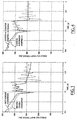
- FIG. 1 an illustration of typical driven wheel torques during an automatic transmission upshift event, such as from first gear to second gear.
- Wheel torque oscillations are readily felt by the occupants of the vehicle. Therefore, a system which allows for removal of the torque converter for cost savings, particularly in a hybrid electric vehicle, and which can provide alternate damping for wheel torque oscillations will prove advantageous.
- the present invention is adapted for application in a motor vehicle comprising an engine, an electrical machine coupled to provide supplemental torque to a torque provided by the engine, a transmission having an input coupled to receive torque provided by the engine, and at least one wheel shaft driven by an output of the transmission, the wheel shaft having a driven end and an end coupled to a respective wheel of the motor vehicle.
- the present invention provides a method for suppressing driveline oscillations comprising: for at least one wheel shaft, sensing a difference in rotational speed between the driven end of the wheel shaft and the wheel shaft's respective wheel, and generating a torque command for the electrical machine to supply a torque which is a function of the difference.
- the present invention provides a method for suppressing driveline oscillations comprising sensing a rotational speed at the output of the transmission to generate a transmission output speed signal, and generating a torque command for the electrical machine to supply a torque which is a function of the transmission output speed signal.
- the present invention provides a method for suppressing driveline oscillations comprising sensing a rotational speed of the engine to generate an engine speed signal; filtering the engine speed signal to substantially eliminate at least a low-frequency range of the engine speed signal below a frequency range of the oscillations and thereby generate a second signal; and generating a torque command for the electrical machine to supply a torque which is a function of the second signal.
- the present invention allows removal of a vehicle's torque converter without introduction of objectionable oscillations in the driveline of the vehicle. Cost and fuel-efficiency advantages will result.
- the powertrain of a motor vehicle such as a hybrid electric vehicle (“HEV").
- the powertrain includes an engine 20, such as an internal combustion engine. Coupled to crankshaft 21 of engine 20 is rotor 22 of a motor-generator, such as starter-alternator 24.
- Starter-alternator 24 is preferably an induction machine, though other electric machine designs can readily be used.
- Starter-alternator 24 is controlled by control module 26.
- Control module 26 includes semiconductor switches to act as an inverter for converting DC electrical power from battery 28 to three-phase AC power provided to stator 30 of starter-alternator 24.
- Control module 26 also preferably includes control circuitry for control of the semiconductor switches, as well as machine control logic for control of starter-alternator 24.
- Starter-alternator 24 acts as a starter motor for cranking engine 20, as a generator when the output of engine 20 is greater than necessary to drive the vehicle, and as a motor to provide supplementary torque as necessary.
- Transmission 32 is preferably an automatic transmission such as a "step ratio" planetary gear transmission or a continuously-variable transmission.
- transmission 32 is actually a transaxle for a front wheel drive vehicle.
- transmission 32 are two "half-shafts" 34 and 36, coupled to drive wheels 38 and 40, respectively, of the vehicle.
- Clutches may also be provided between engine 20 and starter-alternator 24 and between starter-alternator 24 and transmission 32, depending upon the exact functionality desired of the hybrid vehicle's powertrain.
- a transmission output speed (TOS) sensor 42 senses the speed at the output of the transmission (i.e., at the driven ends of half-shafts 34 and 36. Further, wheel speed (WS) sensors 44 and 46 sense the wheel speeds of driven wheels 38 and 40. Additionally, an engine speed sensor 48 senses the rotational speed of engine 20.
- TOS transmission output speed
- WS wheel speed sensors 44 and 46 sense the wheel speeds of driven wheels 38 and 40.
- engine speed sensor 48 senses the rotational speed of engine 20.
- starter-alternator 24 is controlled to provide a countertorque which is based on the "wind-up" speed of a half-shaft 34 or 36.
- the "wind-up" speed is the difference between the speed at the driven end of the half-shaft and the end coupled to the drive wheel.
- the countertorque T SA commanded by control module 26 is a proportional function of the difference between the transmission output speed and a wheel speed.
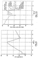
- Figure 3 shows this relationship in block diagram form. As an example of the performance with the gain K of Figure 3 selected as 50 Nms/radian, refer to Figure 4.
- the "undamped" curve shows the wheel torque without any damping provided by starter-alternator 24.
- the "damped" curve shows the wheel torque with damping provided by starter-alternator 24.
- the damping provided by starter-alternator 24 almost completely eliminates the oscillations present in the undamped case.
- the proportional control applied can be combined with integral and/or derivative control, or other known control methodologies can be employed.
- the countertorque T SA can be a function of a difference between the transmission output speed and the average of the speeds of the driven wheels of the vehicle.
- Figure 8 shows the result of using filtered transmission output speed instead of half-shaft wind-up speed, as described immediately above. Compared with the curve where no damping is supplied by starter-alternator 24, damping using the transmission output speed signal alone is very effective to reduce wheel torque oscillations.
- a more precise way of selecting the filter for block 50 relies on using models of a half-shaft, the tire/road interface and the vehicle's mass reflected to the drive wheel.
- the derivation (which is not provided here for the sake of brevity) indicates that a high-pass filter having a transfer function of the following form will work well to isolate the half-shaft wind-up speed from the transmission output speed signal:
- FIG. 10 The control applied in Figure 10 is diagramatically shown in Figure 3C.
- Filtering (block 60) is applied to eliminate the lower-frequency components of the engine speed signal. In this case, two cascaded first-order 4 Hertz high-pass filters were employed. Pure integral control (block 62) is then preferred, as it has been observed that during the time period of interest, the engine output speed signal leads the half-shaft wind-up speed by about 90 degrees.
Abstract
Description
- The present invention relates to use of a supplemental torque source to improve shift quality in a motor vehicle.
- Refer first to Figure 1, an illustration of typical driven wheel torques during an automatic transmission upshift event, such as from first gear to second gear. (The upshift event begins at t=1.4 seconds on the horizontal axis and is complete at about t=2.0 seconds.) The curve reflecting a system with a torque converter shows a torque "hole" at about t=1.4 seconds due to engagement of the shifting clutch and subsequent transfer of torque from the offgoing to the oncoming friction element. Shudder-like oscillations, or "shuffle" in driven wheel torque then continue during the "inertia phase" of the shift until about t=2.0 seconds.
- In order to reduce cost and improve the fuel efficiency of a motor vehicle with an automatic transmission, it has been proposed to remove the vehicle's torque converter. The resulting effect of subtracting the very significant damping effect of the torque converter is also shown in Figure 1. The torque hole at t=1.4 seconds is larger, the oscillations up to t=2.0 seconds are larger, and very substantial oscillations in wheel torque continue beyond t=3.0 seconds. Obviously, much is lost in damping of wheel torque oscillations by removal of the torque converter.
- Wheel torque oscillations are readily felt by the occupants of the vehicle. Therefore, a system which allows for removal of the torque converter for cost savings, particularly in a hybrid electric vehicle, and which can provide alternate damping for wheel torque oscillations will prove advantageous.
- The present invention is adapted for application in a motor vehicle comprising an engine, an electrical machine coupled to provide supplemental torque to a torque provided by the engine, a transmission having an input coupled to receive torque provided by the engine, and at least one wheel shaft driven by an output of the transmission, the wheel shaft having a driven end and an end coupled to a respective wheel of the motor vehicle.
- In one embodiment, the present invention provides a method for suppressing driveline oscillations comprising: for at least one wheel shaft, sensing a difference in rotational speed between the driven end of the wheel shaft and the wheel shaft's respective wheel, and generating a torque command for the electrical machine to supply a torque which is a function of the difference.
- In a second embodiment, the present invention provides a method for suppressing driveline oscillations comprising sensing a rotational speed at the output of the transmission to generate a transmission output speed signal, and generating a torque command for the electrical machine to supply a torque which is a function of the transmission output speed signal.
- In a third embodiment, the present invention provides a method for suppressing driveline oscillations comprising sensing a rotational speed of the engine to generate an engine speed signal; filtering the engine speed signal to substantially eliminate at least a low-frequency range of the engine speed signal below a frequency range of the oscillations and thereby generate a second signal; and generating a torque command for the electrical machine to supply a torque which is a function of the second signal.
- The present invention allows removal of a vehicle's torque converter without introduction of objectionable oscillations in the driveline of the vehicle. Cost and fuel-efficiency advantages will result.
- It is an advantage of the present invention that it provides damping of wheel torque in a motor vehicle, in order to improve comfort for occupants of the vehicle.
- It is a further advantage of the present invention that it facilitates removal of the torque converter of a motor vehicle without introducing objectionable wheel torque oscillations, particularly during transmission shift events.
- The present invention will now be described further, by way of example, with reference to the accompanying drawings, in which:
- Figure 1 is a graph of driven wheel torque versus time during a transmission upshift for a prior art vehicle having a torque converter and for the same vehicle having the torque converter removed;
- Figure 2 is a block diagram of a motor vehicle
powertrain including a starter-
alternator 24 interposed between anengine 20 and atransmission 32; - Figure 3A illustrates the determination of starter-alternator torque to dampen drivetrain oscillations, according to one embodiment of the present invention;
- Figure 3B illustrates the determination of starter-alternator torque to dampen drivetrain oscillations, according to a second embodiment of the present invention;
- Figure 3C illustrates the determination of starter-alternator torque to dampen drivetrain oscillations, according to a third embodiment of the present invention;
- Figure 4 illustrates damping performance of the embodiment of Figure 3A;
- Figure 5 illustrates the damping torque applied by
starter-
alternator 24 to provide the damping performance illustrated in Figure 4; - Figure 6 illustrates the effect of a modification of the embodiment of Figure 3A to add a one-time torque pulse;
- Figure 7 illustrates the speed of the output of
transmission 32 versus time during an upshifting event; - Figure 8 illustrates damping performance of the embodiment of Figure 3B;
- Figure 9 illustrates the speed of
engine 20 versus time during an upshifting event; and - Figure 10 illustrates damping performance of the embodiment of Figure 3C.
-
- Refer to Figure 2. Illustrated there is the powertrain of a motor vehicle such as a hybrid electric vehicle ("HEV"). The powertrain includes an
engine 20, such as an internal combustion engine. Coupled tocrankshaft 21 ofengine 20 isrotor 22 of a motor-generator, such as starter-alternator 24. Starter-alternator 24 is preferably an induction machine, though other electric machine designs can readily be used. Starter-alternator 24 is controlled bycontrol module 26.Control module 26 includes semiconductor switches to act as an inverter for converting DC electrical power frombattery 28 to three-phase AC power provided tostator 30 of starter-alternator 24.Control module 26 also preferably includes control circuitry for control of the semiconductor switches, as well as machine control logic for control of starter-alternator 24. It should be recognised that many sensors for effecting such control are not shown in Figure 2, as they are not germane to the present invention and a need for them will be readily recognised by those of ordinary skill in the art. Starter-alternator 24 acts as a starter motor for crankingengine 20, as a generator when the output ofengine 20 is greater than necessary to drive the vehicle, and as a motor to provide supplementary torque as necessary. -
Transmission 32 is preferably an automatic transmission such as a "step ratio" planetary gear transmission or a continuously-variable transmission. In Figure 2,transmission 32 is actually a transaxle for a front wheel drive vehicle. Driven bytransmission 32 are two "half-shafts" 34 and 36, coupled to drivewheels - Clutches may also be provided between
engine 20 and starter-alternator 24 and between starter-alternator 24 andtransmission 32, depending upon the exact functionality desired of the hybrid vehicle's powertrain. - A transmission output speed (TOS)
sensor 42 senses the speed at the output of the transmission (i.e., at the driven ends of half-shafts sensors wheels engine 20. The signals of each of the above sensors are made available to controlmodule 26, either by hard-wiring or through a data communication link from other module(s) to which the sensors are directly coupled. - In a first variation of the present invention, starter-
alternator 24 is controlled to provide a countertorque which is based on the "wind-up" speed of a half-shaft control module 26 is a proportional function of the difference between the transmission output speed and a wheel speed. Figure 3 shows this relationship in block diagram form. As an example of the performance with the gain K of Figure 3 selected as 50 Nms/radian, refer to Figure 4. The "undamped" curve shows the wheel torque without any damping provided by starter-alternator 24. The "damped" curve shows the wheel torque with damping provided by starter-alternator 24. Clearly, the damping provided by starter-alternator 24 almost completely eliminates the oscillations present in the undamped case. If appropriate in a given case, the proportional control applied can be combined with integral and/or derivative control, or other known control methodologies can be employed. Also, the countertorque TSA can be a function of a difference between the transmission output speed and the average of the speeds of the driven wheels of the vehicle. - Referring additionally to Figure 5, illustrated there is the torque provided by starter-
alternator 24 in the just-discussed example of Figure 4. - One will note in Figure 4 that a torque hole at t=1.4 seconds still exists, however, even when starter-
alternator 24 is acting to provide damping. This hole can be reduced if starter-alternator 24 is commanded to provide a torque "pulse" to counteract the torque hole. Referring to Figure 6, the effect of a 0.3 second, 30 N-m torque pulse applied at t=1.4 seconds is illustrated. The torque hole at t=1.4 seconds is substantially reduced. Timing, intensity and duration of such a torque pulse can be determined through vehicle testing, laboratory testing or adaptive learning during the vehicle's operation. - A more cost-effective system might be provided if reliance on actual sensing of wheel speed signals can be dispensed with. It has been observed by the inventors that much of the useful information provided by the "wind-up" speed of the half-shafts is available in the transmission output speed signal alone. Refers to Figure 7 and 3B. In Figure 7, it is seen that at t=1.4 seconds, higher frequency content begins to appear in the transmission output speed signal. The transmission output speed signal can be high-pass filtered (block 50), in order to remove the low frequency content of the signal attributable to acceleration of the vehicle. For some vehicles, the shuffle-mode oscillations which we wish to dampen occur in the range of 5 to 8 hertz. For this example, two cascaded first-order high-pass filters having break frequencies of 0.75 hertz were used. Proportional (block 52) and integral (block 54) control can be applied to result in the commanded torque to be provided by starter-
alternator 24. - Figure 8 shows the result of using filtered transmission output speed instead of half-shaft wind-up speed, as described immediately above. Compared with the curve where no damping is supplied by starter-
alternator 24, damping using the transmission output speed signal alone is very effective to reduce wheel torque oscillations. - A more precise way of selecting the filter for
block 50 relies on using models of a half-shaft, the tire/road interface and the vehicle's mass reflected to the drive wheel. The derivation (which is not provided here for the sake of brevity) indicates that a high-pass filter having a transfer function of the following form will work well to isolate the half-shaft wind-up speed from the transmission output speed signal:where
- ωt = transmission output speed
- ωso = half-shaft output speed (wheel speed)
- k = half-shaft stiffness translated into the rotational domain
- m = vehicle mass translated into the rotational domain
- b = tire/road friction translated into the rotational domain.
-
- Using nominal values for the parameters in the above equation results in:
s s - An additional variation of the present invention can also be employed. Here, instead of the variation of using only transmission output speed for control of starter-alternator 24 (Figures 3B and 8), engine speed alone can be used. Refer to Figure 9, where engine speed variation during a shift event is illustrated. Higher-frequency content is apparent at time t=2.0 seconds (the approximate end of the shift), due to the disturbance in the system invoked by the transmission shift event. The information contained in the engine speed signal at that point can be used to control starter-
alternator 24 to provide countertorque for damping wheel torque oscillations. Refer additionally to Figure 10. In Figure 10, damping is applied by starter-alternator 24 only beginning at t=2.0 seconds. At that point, oscillations are very significantly damped when compared to the undamped case. The control applied in Figure 10 is diagramatically shown in Figure 3C. Filtering (block 60) is applied to eliminate the lower-frequency components of the engine speed signal. In this case, two cascaded first-order 4 Hertz high-pass filters were employed. Pure integral control (block 62) is then preferred, as it has been observed that during the time period of interest, the engine output speed signal leads the half-shaft wind-up speed by about 90 degrees.
Claims (10)
- In a motor vehicle comprising an engine (20), an electrical machine (24) coupled to provide supplemental torque to a torque provided by said engine (20), a transmission (32) having an input coupled to receive torque provided by said engine, and at least one wheel shaft (34,36) driven by an output of said transmission (32), said wheel shaft (34,36) having a driven end and an end coupled to a respective wheel (38,40) of said motor vehicle, a method for suppressing driveline oscillations comprising:for at least one said wheel shaft (34,36), sensing a difference in rotational speed between said driven end of said wheel shaft and said wheel shaft's respective wheel; andgenerating a torque command for said electrical machine (24) to supply a torque which is a function of said difference.
- A method for suppressing driveline oscillations as claimed in Claim 1, wherein said torque command is generated during a shifting event of said transmission.
- A method for suppressing driveline oscillations as claimed in Claim 1, wherein said torque command contains a term proportional to said difference.
- In a motor vehicle comprising an engine, an electrical machine coupled to provide supplemental torque to a torque provided by said engine, a transmission having an input coupled to receive torque provided by said engine, and at least one wheel shaft driven by an output of said transmission, said wheel shaft having a driven end and an end coupled to a wheel of said motor vehicle, a method for suppressing driveline oscillations comprising:sensing a rotational speed at said output of said transmission to generate a transmission output speed signal; andgenerating a torque command for said electrical machine to supply a torque which is a function of said transmission output speed signal.
- A method as claimed in Claim 4, further comprising:filtering said transmission output speed signal to substantially eliminate at least a low-frequency range of said signal below a frequency range of said oscillations and thereby generate a second signal;
wherein said torque command is a function of said second signal. - A method as claimed in Claim 4, further comprising processing said transmission output speed signal in view of one or more driveline characteristics of said motor vehicle to generate a second signal;
wherein said torque command is a function of said second signal. - A method as claimed in Claim 4, further comprising:sensing rotational speeds of one or more of said wheels to generate one or more wheel speed signals;
wherein said torque command is a function of said one or more wheel speed signals. - A method as claimed in Claim 7, further comprising combining said one or more wheel speed signals to generate a combined wheel speed signal;
wherein said torque command is a function of said combined wheel speed signal. - In a motor vehicle comprising an engine, an electrical machine coupled to provide supplemental torque to a torque provided by said engine, a transmission having an input coupled to receive torque provided by said engine, and at least one wheel shaft driven by an output of said transmission, said wheel shaft having a driven end and an end coupled to a wheel of said motor vehicle, a method for suppressing driveline oscillations comprising:sensing a rotational speed of said engine to generate an engine speed signal;filtering said engine speed signal to substantially eliminate at least a low-frequency range of said engine speed signal below a frequency range of said oscillations and thereby generate a second signal;generating a torque command for said electrical machine to supply a torque which is a function of said second signal.
- A method for suppressing driveline oscillations as claimed in Claim 9, wherein said torque command is generated after a shifting event of said transmission, to counteract driveline oscillations introduced by said shifting event.
Applications Claiming Priority (2)
| Application Number | Priority Date | Filing Date | Title |
|---|---|---|---|
| US09/376,731 US6193628B1 (en) | 1999-08-17 | 1999-08-17 | Vehicle shift quality using a supplemental torque source |
| US376731 | 1999-08-17 |
Publications (3)
| Publication Number | Publication Date |
|---|---|
| EP1077150A2 true EP1077150A2 (en) | 2001-02-21 |
| EP1077150A3 EP1077150A3 (en) | 2004-04-07 |
| EP1077150B1 EP1077150B1 (en) | 2007-09-19 |
Family
ID=23486237
Family Applications (1)
| Application Number | Title | Priority Date | Filing Date |
|---|---|---|---|
| EP00306853A Expired - Lifetime EP1077150B1 (en) | 1999-08-17 | 2000-08-10 | Supplemental torque source for reducing drive line oscillations |
Country Status (3)
| Country | Link |
|---|---|
| US (1) | US6193628B1 (en) |
| EP (1) | EP1077150B1 (en) |
| DE (1) | DE60036439T2 (en) |
Cited By (8)
| Publication number | Priority date | Publication date | Assignee | Title |
|---|---|---|---|---|
| GB2372021A (en) * | 2001-02-09 | 2002-08-14 | Visteon Global Tech Inc | Integrating a starter-generator with an automatic transmission |
| EP1466772A2 (en) | 2003-04-11 | 2004-10-13 | Deere & Company | Vehicle driving system |
| US7024290B2 (en) | 2004-07-30 | 2006-04-04 | Ford Global Technologies, Llc | Active motor damping to mitigate electric vehicle driveline oscillations |
| WO2006099982A2 (en) * | 2005-03-24 | 2006-09-28 | Zf Friedrichshafen Ag | Method for operating a drive train of a motor vehicle |
| DE102008000870A1 (en) * | 2008-03-28 | 2009-10-01 | Zf Friedrichshafen Ag | Drive train operating method for hybrid motor vehicle, involves controlling electric motor of hybrid drive for damping oscillations of drive train such that actual speed of electric motor corresponds reference variable |
| DE102007013336B4 (en) * | 2006-03-22 | 2017-08-10 | GM Global Technology Operations LLC (n. d. Ges. d. Staates Delaware) | A method of controlling vehicle driveline torque to handle jerking using multivariable active driveline damping |
| GB2570937A (en) * | 2018-02-13 | 2019-08-14 | Ford Global Tech Llc | A motor vehicle having active shuffle reduction |
| EP2726353B1 (en) | 2011-06-28 | 2020-10-07 | Schaeffler Technologies AG & Co. KG | Hybrid drive train having an active torsional vibration damping and method for carrying out the active torsional vibration damping |
Families Citing this family (24)
| Publication number | Priority date | Publication date | Assignee | Title |
|---|---|---|---|---|
| JP2003524155A (en) * | 1999-12-08 | 2003-08-12 | ロベルト・ボッシュ・ゲゼルシャフト・ミト・ベシュレンクテル・ハフツング | Method and apparatus for determining the speed value of at least one drive wheel of a motor vehicle |
| DE10017281A1 (en) * | 2000-04-06 | 2001-10-11 | Bosch Gmbh Robert | Controlling drive unit involves reducing drive unit output parameter during presence of oscillations in drive train until they decay |
| US7116068B2 (en) * | 2002-04-12 | 2006-10-03 | Ford Global Technologies, Llc | Diagnostic system and method for an electric motor using torque estimates |
| US7116077B2 (en) * | 2002-04-12 | 2006-10-03 | Ford Global Technologies, Llc | Diagnostic system and method for an electric motor using torque estimates |
| ATE446210T1 (en) * | 2002-12-25 | 2009-11-15 | Toyota Motor Co Ltd | HYBRID DRIVE CONTROL |
| US7261671B2 (en) * | 2003-09-10 | 2007-08-28 | Ford Global Technologies, Llc | Hybrid vehicle powertrain with a multiple-ratio power transmission mechanism |
| US7160223B2 (en) * | 2003-09-10 | 2007-01-09 | Ford Global Technologies, Llc | Method for inhibiting engine stalling in a hybrid vehicle |
| US6915198B2 (en) * | 2003-09-11 | 2005-07-05 | Ford Global Technologies, Llc | Vehicle fast torque coordination |
| US6907337B2 (en) * | 2003-09-11 | 2005-06-14 | Ford Global Technologies, Llc | Vehicle torque resolution |
| US6862511B1 (en) | 2003-09-11 | 2005-03-01 | Ford Global Technologies, Llc | Vehicle torque coordination |
| US7680567B2 (en) * | 2004-07-29 | 2010-03-16 | Ford Global Technologies, Llc | Method for reducing driveline vibration in a hybrid electric vehicle powertrain |
| US20060047400A1 (en) * | 2004-08-25 | 2006-03-02 | Raj Prakash | Method and apparatus for braking and stopping vehicles having an electric drive |
| US7223203B2 (en) * | 2004-09-01 | 2007-05-29 | Ford Global Technologies, Llc | Method of detecting torque disturbances in a hybrid vehicle |
| JP4835171B2 (en) * | 2006-01-27 | 2011-12-14 | トヨタ自動車株式会社 | Motor drive device |
| US8010263B2 (en) * | 2006-03-22 | 2011-08-30 | GM Global Technology Operations LLC | Method and apparatus for multivariate active driveline damping |
| US8161843B2 (en) * | 2007-08-21 | 2012-04-24 | Florida State University Research Foundation | Damping motor and control approach for mitigating torsional backlash, damping critical geartrain speeds, and providing improved torque control in mechanical gears |
| US8027771B2 (en) * | 2007-09-13 | 2011-09-27 | GM Global Technology Operations LLC | Method and apparatus to monitor an output speed sensor during operation of an electro-mechanical transmission |
| US8682545B2 (en) * | 2010-06-15 | 2014-03-25 | Ford Global Technologies, Llc | Damping oscillations during a gear ratio change of a dual clutch powershift transmission |
| DE102011012840A1 (en) * | 2011-03-03 | 2012-09-06 | Audi Ag | Method for determining operating parameter of motor vehicle, involves applying drive force of electric drive machine on assigned wheel through shaft, where torque of wheel or drive speed of motor vehicle is evaluated |
| US9457787B2 (en) | 2012-05-07 | 2016-10-04 | Ford Global Technologies, Llc | Method and system to manage driveline oscillations with motor torque adjustment |
| US10919518B2 (en) | 2017-03-09 | 2021-02-16 | Ford Global Technologies, Llc | Methods and system for improving hybrid vehicle transmission gear shifting |
| US10513256B2 (en) | 2017-03-09 | 2019-12-24 | Ford Global Technologies, Llc | Methods and system for improving hybrid vehicle transmission gear shifting |
| US10518781B2 (en) | 2018-03-20 | 2019-12-31 | Ford Global Technologies, Llc | Powertrain with anti-shuffle control |
| JP7294416B2 (en) * | 2019-05-20 | 2023-06-20 | 日産自動車株式会社 | Shift control method and shift control system |
Family Cites Families (7)
| Publication number | Priority date | Publication date | Assignee | Title |
|---|---|---|---|---|
| DE2748697C2 (en) | 1977-10-29 | 1985-10-24 | Volkswagenwerk Ag, 3180 Wolfsburg | Drive arrangement for a vehicle, in particular a passenger vehicle |
| DE3022373A1 (en) | 1980-06-14 | 1981-12-24 | Volkswagenwerk Ag | VEHICLE, PARTICULARLY PERSONAL VEHICLES |
| DE3048972C2 (en) | 1980-12-24 | 1995-01-26 | Luk Lamellen & Kupplungsbau | Drive unit |
| JP3314484B2 (en) * | 1992-12-28 | 2002-08-12 | 株式会社デンソー | Vehicle damping device |
| JP3350201B2 (en) | 1994-02-14 | 2002-11-25 | 株式会社日立製作所 | Torque feedback shift control apparatus and method |
| JP3622338B2 (en) | 1996-05-28 | 2005-02-23 | トヨタ自動車株式会社 | Vehicle shift control device |
| DE19721298C2 (en) * | 1997-05-21 | 2001-09-06 | Mannesmann Sachs Ag | Hybrid travel drive for a motor vehicle |
-
1999
- 1999-08-17 US US09/376,731 patent/US6193628B1/en not_active Expired - Lifetime
-
2000
- 2000-08-10 DE DE60036439T patent/DE60036439T2/en not_active Expired - Lifetime
- 2000-08-10 EP EP00306853A patent/EP1077150B1/en not_active Expired - Lifetime
Non-Patent Citations (1)
| Title |
|---|
| None |
Cited By (17)
| Publication number | Priority date | Publication date | Assignee | Title |
|---|---|---|---|---|
| GB2372021B (en) * | 2001-02-09 | 2002-12-31 | Visteon Global Tech Inc | Integrating a starter-generator with an automatic transmission |
| GB2372021A (en) * | 2001-02-09 | 2002-08-14 | Visteon Global Tech Inc | Integrating a starter-generator with an automatic transmission |
| EP1466772A2 (en) | 2003-04-11 | 2004-10-13 | Deere & Company | Vehicle driving system |
| EP1466772A3 (en) * | 2003-04-11 | 2006-10-11 | Deere & Company | Vehicle driving system |
| US7287612B2 (en) | 2003-04-11 | 2007-10-30 | Deere & Company | Drive system for vehicles |
| DE102005033354B4 (en) | 2004-07-30 | 2022-08-25 | Ford Global Technologies, Llc | Method for damping vibrations in the drive train of an electric vehicle |
| US7024290B2 (en) | 2004-07-30 | 2006-04-04 | Ford Global Technologies, Llc | Active motor damping to mitigate electric vehicle driveline oscillations |
| WO2006099982A2 (en) * | 2005-03-24 | 2006-09-28 | Zf Friedrichshafen Ag | Method for operating a drive train of a motor vehicle |
| WO2006099982A3 (en) * | 2005-03-24 | 2006-11-30 | Zahnradfabrik Friedrichshafen | Method for operating a drive train of a motor vehicle |
| US7846061B2 (en) | 2005-03-24 | 2010-12-07 | Zf Friedrichshafen Ag | Method for operating a drive train of a motor vehicle |
| US7998025B2 (en) | 2005-03-24 | 2011-08-16 | Zf Friedrichshafen Ag | Method for operating a drivetrain of a motor vehicle |
| DE102007013336B4 (en) * | 2006-03-22 | 2017-08-10 | GM Global Technology Operations LLC (n. d. Ges. d. Staates Delaware) | A method of controlling vehicle driveline torque to handle jerking using multivariable active driveline damping |
| DE102008000870A1 (en) * | 2008-03-28 | 2009-10-01 | Zf Friedrichshafen Ag | Drive train operating method for hybrid motor vehicle, involves controlling electric motor of hybrid drive for damping oscillations of drive train such that actual speed of electric motor corresponds reference variable |
| EP2726353B1 (en) | 2011-06-28 | 2020-10-07 | Schaeffler Technologies AG & Co. KG | Hybrid drive train having an active torsional vibration damping and method for carrying out the active torsional vibration damping |
| GB2570937B (en) * | 2018-02-13 | 2020-07-01 | Ford Global Tech Llc | A motor vehicle having active shuffle reduction |
| US10871119B2 (en) | 2018-02-13 | 2020-12-22 | Ford Global Technologies, Llc | Motor vehicle having active shuffle reduction |
| GB2570937A (en) * | 2018-02-13 | 2019-08-14 | Ford Global Tech Llc | A motor vehicle having active shuffle reduction |
Also Published As
| Publication number | Publication date |
|---|---|
| US6193628B1 (en) | 2001-02-27 |
| EP1077150B1 (en) | 2007-09-19 |
| DE60036439D1 (en) | 2007-10-31 |
| DE60036439T2 (en) | 2008-05-08 |
| EP1077150A3 (en) | 2004-04-07 |
Similar Documents
| Publication | Publication Date | Title |
|---|---|---|
| EP1077150B1 (en) | Supplemental torque source for reducing drive line oscillations | |
| JP5325190B2 (en) | How to start the vehicle | |
| JP4358264B2 (en) | Hybrid vehicle | |
| JPH09177830A (en) | Driving device for automobile | |
| JP3337423B2 (en) | Hybrid traveling drive for powered vehicles | |
| US20060025905A1 (en) | Active motor damping to mitigate electric vehicle driveline oscillations | |
| US9005077B2 (en) | Method to reduce lash clunk in a hybrid electric vehicle | |
| US20100019709A1 (en) | Method for controlling the electric motor of a hybrid or electric vehicle | |
| CN102806908B (en) | For the method for the operational power system in response to accessory load | |
| CN102421616A (en) | Sprung mass damping control system of vehicle | |
| US6629025B2 (en) | Surge suppression control for a motor vehicle drivetrain | |
| US9278681B2 (en) | Hybrid electric vehicle driveline active damping and transient smoothness control | |
| JP3220121B2 (en) | Drives for motor vehicles | |
| CN106828070B (en) | Control device for power transmission device | |
| JP4550987B2 (en) | Hybrid vehicle power generator | |
| JP4075210B2 (en) | Drive device | |
| US11813943B2 (en) | Method and drive control device for operating at least two electric drive machines in the event of a change in load and motor vehicle with a drive control device | |
| JP4816243B2 (en) | VEHICLE POWER DEVICE AND CONTROL DEVICE THEREOF | |
| JP7193264B2 (en) | electric vehicle | |
| KR102656322B1 (en) | How to control a rotating electric machine to compensate for torque oscillations in the traction chain of a car | |
| KR101827160B1 (en) | Method for controlling engine operating point during clutch lock-up in hybrid vehicle | |
| JP2003161181A (en) | Operation method for driving structure of hybrid vehicle provided with transmission | |
| JP2024053912A (en) | Vehicle control device | |
| CN109383487B (en) | Driveline system with nested loop damping control | |
| KR100862466B1 (en) | Shock improvement method for engine off of a Hybrid car |
Legal Events
| Date | Code | Title | Description |
|---|---|---|---|
| PUAI | Public reference made under article 153(3) epc to a published international application that has entered the european phase |
Free format text: ORIGINAL CODE: 0009012 |
|
| AK | Designated contracting states |
Kind code of ref document: A2 Designated state(s): AT BE CH CY DE DK ES FI FR GB GR IE IT LI LU MC NL PT SE |
|
| AX | Request for extension of the european patent |
Free format text: AL;LT;LV;MK;RO;SI |
|
| PUAL | Search report despatched |
Free format text: ORIGINAL CODE: 0009013 |
|
| AK | Designated contracting states |
Kind code of ref document: A3 Designated state(s): AT BE CH CY DE DK ES FI FR GB GR IE IT LI LU MC NL PT SE |
|
| AX | Request for extension of the european patent |
Extension state: AL LT LV MK RO SI |
|
| RIC1 | Information provided on ipc code assigned before grant |
Ipc: 7B 60K 6/04 A Ipc: 7F 16H 61/04 B |
|
| 17P | Request for examination filed |
Effective date: 20040904 |
|
| AKX | Designation fees paid |
Designated state(s): DE GB SE |
|
| 17Q | First examination report despatched |
Effective date: 20050222 |
|
| GRAP | Despatch of communication of intention to grant a patent |
Free format text: ORIGINAL CODE: EPIDOSNIGR1 |
|
| GRAS | Grant fee paid |
Free format text: ORIGINAL CODE: EPIDOSNIGR3 |
|
| GRAA | (expected) grant |
Free format text: ORIGINAL CODE: 0009210 |
|
| AK | Designated contracting states |
Kind code of ref document: B1 Designated state(s): DE GB SE |
|
| REG | Reference to a national code |
Ref country code: GB Ref legal event code: FG4D |
|
| REG | Reference to a national code |
Ref country code: GB Ref legal event code: 732E |
|
| REF | Corresponds to: |
Ref document number: 60036439 Country of ref document: DE Date of ref document: 20071031 Kind code of ref document: P |
|
| REG | Reference to a national code |
Ref country code: SE Ref legal event code: TRGR |
|
| PLBE | No opposition filed within time limit |
Free format text: ORIGINAL CODE: 0009261 |
|
| STAA | Information on the status of an ep patent application or granted ep patent |
Free format text: STATUS: NO OPPOSITION FILED WITHIN TIME LIMIT |
|
| 26N | No opposition filed |
Effective date: 20080620 |
|
| REG | Reference to a national code |
Ref country code: DE Ref legal event code: R082 Ref document number: 60036439 Country of ref document: DE Representative=s name: DOERFLER, THOMAS, DR.-ING., DE |
|
| PGFP | Annual fee paid to national office [announced via postgrant information from national office to epo] |
Ref country code: GB Payment date: 20170725 Year of fee payment: 18 |
|
| PGFP | Annual fee paid to national office [announced via postgrant information from national office to epo] |
Ref country code: SE Payment date: 20170810 Year of fee payment: 18 |
|
| REG | Reference to a national code |
Ref country code: SE Ref legal event code: EUG |
|
| GBPC | Gb: european patent ceased through non-payment of renewal fee |
Effective date: 20180810 |
|
| PG25 | Lapsed in a contracting state [announced via postgrant information from national office to epo] |
Ref country code: SE Free format text: LAPSE BECAUSE OF NON-PAYMENT OF DUE FEES Effective date: 20180811 |
|
| PG25 | Lapsed in a contracting state [announced via postgrant information from national office to epo] |
Ref country code: GB Free format text: LAPSE BECAUSE OF NON-PAYMENT OF DUE FEES Effective date: 20180810 |
|
| PGFP | Annual fee paid to national office [announced via postgrant information from national office to epo] |
Ref country code: DE Payment date: 20190715 Year of fee payment: 20 |
|
| REG | Reference to a national code |
Ref country code: DE Ref legal event code: R071 Ref document number: 60036439 Country of ref document: DE |