EP1077074A2 - Nose filter and process for producing the same - Google Patents
Nose filter and process for producing the same Download PDFInfo
- Publication number
- EP1077074A2 EP1077074A2 EP00202857A EP00202857A EP1077074A2 EP 1077074 A2 EP1077074 A2 EP 1077074A2 EP 00202857 A EP00202857 A EP 00202857A EP 00202857 A EP00202857 A EP 00202857A EP 1077074 A2 EP1077074 A2 EP 1077074A2
- Authority
- EP
- European Patent Office
- Prior art keywords
- filter
- nasal
- filter housing
- housing
- disc
- Prior art date
- Legal status (The legal status is an assumption and is not a legal conclusion. Google has not performed a legal analysis and makes no representation as to the accuracy of the status listed.)
- Withdrawn
Links
Images


Classifications
-
- A—HUMAN NECESSITIES
- A62—LIFE-SAVING; FIRE-FIGHTING
- A62B—DEVICES, APPARATUS OR METHODS FOR LIFE-SAVING
- A62B23/00—Filters for breathing-protection purposes
- A62B23/06—Nose filters
Definitions
- the invention relates to a nasal filter and a method for its production, the nasal filter can be used in particular in people who are sensitive to pollen, dust, microspores etc. as allergy sufferers and can also be worn by people who are in sterile rooms, for. B. work in the hospital area (operating room).
- Nasal filters are well known and are also described several times in the patent literature.
- WO 99/11326 discloses a nasal filter which is used as a compact body in each nasal passage separately.
- the filter body in cylindrical form, is enclosed by a porous fabric and has a brim-like widening on the side facing the nostril.
- the disadvantage of this solution lies in the fact that the shape of the nasal cavity (nasal passage) is not individually adapted to the wearer and the sealing against "foreign air" passing through is only achieved via the edge provided with an adhesive component. The comfort of this solution, which is very simple, takes some getting used to for the user.
- a filter device is presented in WO 95/33520, the special feature of which is that 2 Filter elements are connected to one another in one plane using a handle. Every filter element consists of an annular frame made of deformable latex material, which is the real thing Holds the filter element in position. The bridge, which is kinked in the middle, lies on the nasal septum and is used to remove the filter device if necessary.
- the filter element is like this processed that it has a disc-shaped shape and by the flexible latex frame essentially adapts to the circumstances of the nasal passage. The disadvantage of this solution then there is that leaks can still be permitted due to inexact fit and the effect of collecting z. B. cereal pollen, dust mites or other microspores are not is guaranteed.
- an air filter for insertion into the nostril which consists of plug-in bodies connected in parallel, the filter effect being achieved by interchangeable filter elements.
- a so-called “chimney effect" to increase the air throughput is not even effective. It is also to be feared that, due to the elastic connecting bridge between the two plug-in bodies, these are inclined towards one another, so that secondary air can pass unfiltered, especially since no further sealing measures are provided on the surfaces of the plug-in bodies.
- the invention is therefore based on the object of offering a solution which overcomes the disadvantages of the prior art and is particularly aimed at realizing a secure fit of the filter with optimum filtering action and high wearing comfort.
- the object is achieved in that the nasal filter is designed in the combination of the individual components to form a filter unit and steps for its expedient manufacture are specified.
- the two filter housings arranged parallel to each other essentially have one cylindrical shape and are ergonomically reshaped the nose interior, also for Support of holding the shape of so-called nasal olives can be used.
- This post-forming is made possible by physiologically harmless and thermally or machinable materials, such as. B. polymeric plastics are used. These also have the advantage that they are odorless and can be individually colored. Inside there is a cylindrical to oval cavity with a predominantly oval opening at the lower end. As a special feature, the opening facing the inside of the nose has a circumferential edge directed inwards by 90 °, to which a filter disk is attached by means of injection molding or thermal welding. This ensures that the absolute tightness between the filter housing and the filter disc is permanently ensured. The filter disk also takes on an oval shape, following the shape of the lower opening of the filter housing.
- the filter disk in the opposite manner, on Entrance of the filter housing (s) is placed and thus an increase in the filter area and of the volume is accessible.
- the thickness of the filter disc can be varied to achieve a volume filter can be increased.
- the filter housing has 3 basic shapes, which are based on the typical peculiarities of the nasal passages of male and female adults and children, these basic shapes being individually adaptable.
- the cavity of each filter housing has a very smooth surface, which has a positive influence on the flow resistance.
- For an optimal fit of the filter housings to be inserted in parallel, their outer surface is micro-roughened, this effect being supported by elongated lamellar incisions in the upper area of the filter housings. This constructive training and the individual post-forming particularly exclude the passage of "secondary air".
- the micro-roughening of the two filter housings can also be omitted if a concentric corrugation is provided on the circumference thereof instead.
- filter bodies made of physiologically and physically suitable plastic foam, without filter housing, to form, which are only connected to each other with a web.
- the plastic foam fulfills all requirements with regard to the filter properties in the micron range and also the mechanical properties with regard to flexibility, dimensional stability Compressibility.
- the inside of the filter disc contains a thin fleece made of split filter fibers can also be assigned to the polymeric plastics, which have a cover fleece on both Sides are enclosed.
- the permanent static charge of the "inner” fibers causes maximum adhesion of microspores and others contained in the air we breathe Particle.
- the material used for the filter discs corresponds to that for medical Purposes z. B. is used in operations on humans and animals.
- the design of the filter housing and especially the use of split filter fibers in the filter disk increases the filter effect through "spatial effect" and offers a comparatively higher filter capacity and service life as well as more comfortable wearing properties than with conventional surface filters. So that an optimal and even fit of 2 filter housings and filter disks is guaranteed, these are connected to each other via a web, which is also made of polymer plastic.
- the web length is adapted to the corresponding conditions of the wearer, the web width being up to approx. 5 mm and the thickness of the web being up to approx. 0.5 mm.
- the thickness of the web always corresponds to the wall thickness of the filter housing.
- the two ends of a web which is curved approximately in a semicircle, sit flush on the lower part of each filter housing and are fixed there thermally or by gluing to the filter unit.
- the manufacture of the nasal filter should be illustrated by the steps described below:
- polymeric plastic such as. B. polyethylene, Polyprophylen used. This material is easy to treat thermally and by machining.
- the outer basic shape of the filter housing corresponds essentially to the design of the Nasal cavity of male and female adults and children and is on the way of a previous "model impression" of the nasal passage and the nasal septum reshaped to the special circumstances.
- Elastomeric are used as impression materials irreversible materials based on silicone are used.
- this "model impression" is used to adapt the basic shape (outer shape) of the filter housing to the individual circumstances of the wearer, by means of a corresponding casting of the polymer plastic over this "model impression”.
- the surface of the filter housing is micro-roughened, for example by spark erosion, as a result of which a precise, non-slip fit is achieved.
- the “inner” surface of the filter housing is kept very smooth and it is on the top Side of the filter housing by means of thermal shaping an inward-facing circumferential Support edge for the filter disc to be applied there.
- the latter is then either during or after injection molding or during or after a deep-drawing process by means of thermal welding firmly connected to the filter housing.
- the last step is the Positioning and fastening of the web that connects the two filter housings to each other, on the lower and inner side of the filter housing in flush form by means of thermal Welding or gluing.
- the 3 basic shapes mentioned at the beginning can be created the filter housing with regard to the manufacture of the filter housing from the known Nose olives can be varied in a total of up to 36 basic forms. It is also provided here that CAD models in the injection molding process with simultaneous injection molding of the web and with produce simultaneous or subsequent welding of the filter material.
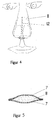
- the nasal filter is understood as a combination of individual elements that form a filter unit merge.
- the nasal filter has 2 connected to one another in parallel via a semicircular web 9
- These filter housings 1, 2 consist primarily of polymeric plastics, especially polyolefins, such as. B. polyethylene, polypropylene or other thermally have it reworked.
- the walls of the filter housings 1, 2 have a thickness of approximately 0.5 mm, which also corresponds to the thickness of the semicircular web 9.
- the filter housings 1, 2 have a smooth surface 4, with their lower end an edge 3 directed inwards by 90 ° is arranged. With this, a filter disc 6 is fixed connected.
- This filter disc 6 consists of split filter fibers 8, each on both Sides are covered by the cover fleece 7.
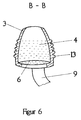
- the filter housings 1, 2 have a micro-roughened Surface 5, in order to improve the fit at the lower end in the filter housing 1, 2nd lamellar incisions 10 are introduced.
- the inward peripheral edge 3 has a width of approx. 1 mm.
- the connection of the filter housing 1, 2 by means of a semicircular Web 9 is designed so that no offset to the outer wall of the filter housing 1, 2 occurs.
- the inlet opening of the filter housing 1, 2, the inward edge 3 and thus also the Filter disc 6 have an oval shape to ensure maximum air passage on.
- the filter disk 6 can also be located at the outward opening the filter housing 1, 2 may be attached in variable thickness. This can advantageously the filter area and the filter volume are increased and the "spatial effect" is increased. Finally, the tight fit of the filter housings 1, 2 can be further improved in that instead of micro-roughening the surfaces, the filter housings 1, 2 are arranged concentrically Ripple 13 received.
Landscapes
- Health & Medical Sciences (AREA)
- Otolaryngology (AREA)
- General Health & Medical Sciences (AREA)
- Business, Economics & Management (AREA)
- Emergency Management (AREA)
- Respiratory Apparatuses And Protective Means (AREA)
- Orthopedics, Nursing, And Contraception (AREA)
Abstract
Description
Die Erfindung betrifft einen Nasenfilter und ein Verfahren zu dessen Herstellung, wobei der
Nasenfilter insbesondere bei Personen eingesetzt werden kann, die als Allergiker empfindlich auf
Pollenflug, Staub, Mikrosporen etc. reagieren als auch von Personen getragen werden kann, die
in sterilen Räumen, z. B. im Krankenhausbereich (OP-Saal), arbeiten.
Nasenfilter sind hinreichend bekannt und auch mehrfach in der Patentliteratur beschrieben.The invention relates to a nasal filter and a method for its production, the nasal filter can be used in particular in people who are sensitive to pollen, dust, microspores etc. as allergy sufferers and can also be worn by people who are in sterile rooms, for. B. work in the hospital area (operating room).
Nasal filters are well known and are also described several times in the patent literature.
So ist in WO 99/11326 ein Nasenfilter bekannt, der als kompakter Körper in jedem Nasengang
separat eingesetzt wird. Der Filterkörper, in zylindrischer Form, wird von einem porigen Gewebe
umschlossen und besitzt an der dem Nasenloch nach außen zugekehrten Seite eine krempenartige
Verbreiterung. Auf dieser wiederum befindet sich eine klebende Komponente, die somit den
Filter fest am Rand des Nasenloches positioniert. Der Filter kann bei Bedarf oder bei Nachlassen
der Funktion unter Überwindung der pflasterähnlichen Verklebung wieder gelöst und ggf
entsprechend entsorgt werden.
Der Nachteil dieser Lösung liegt darin begründet, daß die Formgebung an den Naseninnenraum
(Nasengang) nicht individuell dem Träger angepaßt ist und die Abdichtung gegen hindurchtretende
"Fremdluft" lediglich über den mit einer Klebkomponente versehenen Rand erreicht
wird. Der Tragekomfort ist bei dieser Lösung, die allerdings sehr einfach konzipiert ist, recht
gewöhnungsbedürftig für den Nutzer.For example, WO 99/11326 discloses a nasal filter which is used as a compact body in each nasal passage separately. The filter body, in cylindrical form, is enclosed by a porous fabric and has a brim-like widening on the side facing the nostril. On this in turn there is an adhesive component, which thus positions the filter firmly at the edge of the nostril. If necessary or if the function deteriorates, the filter can be removed again by overcoming the plaster-like adhesion and disposed of accordingly if necessary.
The disadvantage of this solution lies in the fact that the shape of the nasal cavity (nasal passage) is not individually adapted to the wearer and the sealing against "foreign air" passing through is only achieved via the edge provided with an adhesive component. The comfort of this solution, which is very simple, takes some getting used to for the user.
In der WO 95/33520 wird eine Filtereinrichtung vorgestellt deren Besonderheit es ist, daß 2 Filterelemente über ein Griffstück in einer Ebene miteinander verbunden sind. Jedes Filterelement besteht aus einem ringförmigen Rahmen aus deformierbarem Latexmaterial, der das eigentliche Filterelement in Position hält. Der mittig abgeknickte Steg liegt an der Nasenscheidewand und dient zur möglichen Entnahme der Filtereinrichtung bei Bedarf Das Filterelement ist hier so verarbeitet, daß es eine scheibenförmige Gestalt aufweist und durch den biegsamen Latexrahmen im wesentlichen sich den Gegebenheiten des Nasenganges anpaßt. Der Nachteil dieser Lösung besteht dann, daß durch unexakten Sitz dennoch Undichtheiten zugelassen werden können und der Effekt des Auffangens von z. B. Getreidepollen, Staubmilben oder anderer Mikrosporen nicht sicher gewahrleistet ist.A filter device is presented in WO 95/33520, the special feature of which is that 2 Filter elements are connected to one another in one plane using a handle. Every filter element consists of an annular frame made of deformable latex material, which is the real thing Holds the filter element in position. The bridge, which is kinked in the middle, lies on the nasal septum and is used to remove the filter device if necessary. The filter element is like this processed that it has a disc-shaped shape and by the flexible latex frame essentially adapts to the circumstances of the nasal passage. The disadvantage of this solution then there is that leaks can still be permitted due to inexact fit and the effect of collecting z. B. cereal pollen, dust mites or other microspores are not is guaranteed.
Weiter ist nach DE-GM G88 04 725.3 ein Luftfilter zur Einführung in die Nasenöffnung bekannt,
der aus parallel miteinander verbundenen Einsteckkörpern besteht, wobei die Filterwirkung durch
wechselbare Filterelemente erreicht wird. Der durch die vollständige Ausfüllung des Filtergehäuseraums
mit den Filterelementen entstehende Staudruck, insbesondere auch bei zunehmender
Ablagerung aufgenommenen Staubes oder anderer Partikel, bewirkt eine Einschränkung
des Tragekomforts.
Eine sogenannte "Kaminwirkung" zur Verstärkung des Luftdurchsatzes kommt erst gar nicht zur
Geltung. Außerdem ist zu befürchten, daß aufgrund der elastischen Verbindungsbrücke zwischen
den beiden Einsteckkörpern diese einander zugeneigt werden, sodaß dabei Nebenluft ungefiltert
vorbeistreichen kann, zumal an den Oberflächen der Einsteckkörper keine weiteren dichtenden
Maßnahmen vorgesehen sind.Furthermore, according to DE-GM G88 04 725.3, an air filter for insertion into the nostril is known, which consists of plug-in bodies connected in parallel, the filter effect being achieved by interchangeable filter elements. The dynamic pressure resulting from the complete filling of the filter housing space with the filter elements, in particular also with increasing accumulation of dust or other particles, results in a restriction of the wearing comfort.
A so-called "chimney effect" to increase the air throughput is not even effective. It is also to be feared that, due to the elastic connecting bridge between the two plug-in bodies, these are inclined towards one another, so that secondary air can pass unfiltered, especially since no further sealing measures are provided on the surfaces of the plug-in bodies.
Schließlich kann mit GB 886 056 eine verbesserte Schutzeinrichtung für die Atemwege
vorgestellt werden. Die äußere Formgebung und Verbindung der beiden Filtergehäuse kommt der
erfindungsgemäßen Lösung am nächsten, wobei auch dem Tragekomfort insoweit Rechnung
getragen wird, daß die äußeren Flächen aufgerauht sind.
Allerdings ist die Ausstattung der Filter"becher" mit als lose dargestelltein Filtergewebe als
unvorteilhaft anzusehen, da u. U. Bestandteile daraus eingeatmet werden, da sich unmittelbar
daran, an der Spitze der Filter"becher" kreisförmige bzw. punktförmige Öffnungen in Richtung
des Naseninnenraums befinden. Es wird davon auszugehen sein, daß diese Lösung nur Stäube,
Pollen oder andere Partikel in gröberer Form aufnimmt und auf keinen Fall dazu geeignet ist,
Krankheitskeime und Mikrosporen abzufangen. Das Prinzip "Kaminwirkung" wird auch hier
nicht praktiziert. Weitere zusätzliche Maßnahmen zur Verbesserung des Sitzes der Kombination
bzgl. der Rutschsicherheit und Berücksichtigung ergonomischer Besonderheiten sind nicht
vorgesehen.Finally, with GB 886 056, an improved protective device for the respiratory tract can be presented. The outer shape and connection of the two filter housings comes closest to the solution according to the invention, with the wearing comfort being taken into account to the extent that the outer surfaces are roughened.
However, the equipment of the filter "cup" with filter fabric shown as loose is to be regarded as disadvantageous, since u. U. components of it are inhaled, since there are circular or punctiform openings in the direction of the nasal cavity directly at the tip of the filter "cup". It will be assumed that this solution only absorbs dusts, pollen or other particles in a coarser form and is in no way suitable for trapping pathogens and microspores. The "chimney effect" principle is not practiced here either. There are no additional measures to improve the fit of the combination with regard to slip resistance and ergonomic features.
Der Erfindung liegt daher die Aufgabe zugrunde, eine Lösung anzubieten, die die Nachteile des
Standes der Technik überwindet und besonders darauf gerichtet ist, einen sicheren Sitz des Filters
mit optimaler Filtrierwirkung sowie hohem Tragekomfort zu realisieren.
Erfindungsgemäß wird die Aufgabe dadurch gelöst, daß der Nasenfilter in der Kombination der
einzelnen Bestandteile zu einer Filtereinheit gestaltet wird und Schritte zu seiner zweckmäßigen
Herstellung angegeben werden. The invention is therefore based on the object of offering a solution which overcomes the disadvantages of the prior art and is particularly aimed at realizing a secure fit of the filter with optimum filtering action and high wearing comfort.
According to the invention the object is achieved in that the nasal filter is designed in the combination of the individual components to form a filter unit and steps for its expedient manufacture are specified.
Die beiden parallel zueinander angeordneten Filtergehäuse besitzen eine im wesentlichen zylindrische Form und sind ergonomisch dem Naseninnenraum nachgeformt, wobei auch zur Unterstützung des Haltens die Formgebung sogenannter Nasenoliven Verwendungfinden kann.The two filter housings arranged parallel to each other essentially have one cylindrical shape and are ergonomically reshaped the nose interior, also for Support of holding the shape of so-called nasal olives can be used.
Diese Nachformung wird möglich, indem physiologisch unbedenkliche und thermisch bzw. spanend formbare Materialien, wie z. B. polymere Kunststoffe zum Einsatz kommen. Diese besitzen zudem den Vorteil, daß sie geruchsneutral sind und individuell farblich abgestuft werden können. Im inneren befindet sieh ein zylindrisch bis ovaler Hohlraum, der am unteren Ende eine vorwiegend ovale Öffnung besitzt. Die dem Naseninneren zugewandte Öffnung weist als Besonderheit einen um 90° nach innen gerichteten, umlaufenden Rand auf, worauf eine Filterscheibe mittels Spritzgießens oder thermischen Schweißens befestigt ist. Damit wird insbesondere die absolute Dichtheit zwischen Filtergehäuse und Filterscheibe dauerhaft gesichert. Die Filterscheibe nimmt, der Form der unteren Öffnung des Filtergehäuses folgend, ebenfalls eine ovale Gestalt an.This post-forming is made possible by physiologically harmless and thermally or machinable materials, such as. B. polymeric plastics are used. These also have the advantage that they are odorless and can be individually colored. Inside there is a cylindrical to oval cavity with a predominantly oval opening at the lower end. As a special feature, the opening facing the inside of the nose has a circumferential edge directed inwards by 90 °, to which a filter disk is attached by means of injection molding or thermal welding. This ensures that the absolute tightness between the filter housing and the filter disc is permanently ensured. The filter disk also takes on an oval shape, following the shape of the lower opening of the filter housing.
Es kann jedoch auch vorgesehen werden, daß die Filterscheibe in entgegengesetzter Weise, am Eingang des/der Filtergehäuses/-e plaziert ist und damit eine Vergrößerung der Filterfläche und des -volumens erreichbar ist. Gleichzeitig kann die Stärke der Filterscheibe variabel zur Erzielung eines Volumenfilters erhöht werden.However, it can also be provided that the filter disk in the opposite manner, on Entrance of the filter housing (s) is placed and thus an increase in the filter area and of the volume is accessible. At the same time, the thickness of the filter disc can be varied to achieve a volume filter can be increased.
Das Filtergehäuse besitzt 3 Grundformen, die den typischen Eigenheiten des Nasenganges männlicher
und weiblicher Erwachsener sowie Kindern nachempfinden sind, wobei diese
Grundformen weiter individuell anpaßbar sind. Der Hohlraum eines jeden Filtergehäuses weist
eine sehr glatte Oberfläche auf, wodurch der Strömungswiderstand positiv beeinflußt wird. Für
einen optimalen Sitz der parallel einzuführenden Filtergehäuse ist ihre äußere Oberfläche
mikroaufgerauht, wobei dieser Effekt noch durch längliche lamellenartige Einschnitte im oberen
Bereich der Filtergehäuse unterstützt wird. Diese konstruktive Ausbildung und die individuelle
Nachformung schließen insbesondere den Hindurchtritt von "Nebenluft" aus.
Die Mikroaufrauhung der beiden Filtergehäuse kann auch entfallen, wenn stattdessen eine
konzentrische Riffelung am Umfang derselben vorgesehen ist.The filter housing has 3 basic shapes, which are based on the typical peculiarities of the nasal passages of male and female adults and children, these basic shapes being individually adaptable. The cavity of each filter housing has a very smooth surface, which has a positive influence on the flow resistance. For an optimal fit of the filter housings to be inserted in parallel, their outer surface is micro-roughened, this effect being supported by elongated lamellar incisions in the upper area of the filter housings. This constructive training and the individual post-forming particularly exclude the passage of "secondary air".
The micro-roughening of the two filter housings can also be omitted if a concentric corrugation is provided on the circumference thereof instead.
Letztlich ist es möglich, Filterkörper aus physiologisch und physikalisch geeignetem Kunststoff-Schaum, ohne Filtergehause, zu bilden, die lediglich mit einem Steg miteinander verbunden sind. Der Kunststoff-Schaum erfüllt dabei alle Forderungen bzgl. der Filtereigenschaften im micron-Bereich und auch der mechanischen Eigenschaften hinsichtlich Flexibilität, Formstabilität Kompressibilität. Ultimately, it is possible to use filter bodies made of physiologically and physically suitable plastic foam, without filter housing, to form, which are only connected to each other with a web. The plastic foam fulfills all requirements with regard to the filter properties in the micron range and also the mechanical properties with regard to flexibility, dimensional stability Compressibility.
Die Filterscheibe enthält in ihrem Inneren ein dünnes Vlies aus gesplitteten Filterfasern, die ebenfalls den polymeren Kunststoffen zuzuordnen sind, welche von einem Deckvlies an beiden Seiten umschlossen sind. Die permanent vorhandene statische Aufladung der "inneren" Fasern bewirkt eine maximale Adhäsion von in der Atemluft enthaltener Mikrosporen und anderer Partikel. Das verwendete Material der Filterscheiben entspricht dem, welches für medizinische Zwecke z. B. bei Operationen an Mensch und Tier eingesetzt wird.The inside of the filter disc contains a thin fleece made of split filter fibers can also be assigned to the polymeric plastics, which have a cover fleece on both Sides are enclosed. The permanent static charge of the "inner" fibers causes maximum adhesion of microspores and others contained in the air we breathe Particle. The material used for the filter discs corresponds to that for medical Purposes z. B. is used in operations on humans and animals.
Die Ausbildung des Filtergehäuses und besonders die Verwendung von gesplitteten Filterfasern
in der Filterscheibe erhöht den Filtereffekt durch "Raumwirkung" und bietet eine vergleichsweise
höhere Filterkapazität und Nutzungsdauer sowie angenehmere Trageeigenschaften als bei
herkömmlichen Oberflächenfiltern.
Damit ein optimaler und gleichmäßiger Sitz von 2 Filtergehäusen nebst Filterscheiben garantiert
ist, sind diese über einen Steg, der auch aus polymerem Kunststoff gefertigt ist, miteinander
verbunden.
Die Steglänge wird dabei den entsprechenden Gegebenheiten des Trägers angepaßt, wobei die
Stegbreite bis ca. 5 mm und die Stärke des Steges bis ca. 0,5 mm betragen kann. Die Stärke des
Steges entspricht dabei stets der Wandstärke des Filtergehäuses. Die beiden Enden eines Steges,
der etwa halbkreisförmig gebogen ist, sitzen am unteren Teil eines jeden Filtergehäuses bündig
auf und sind dort thermisch oder durch Klebung mit diesem fest zur Filtereinheit verbunden.The design of the filter housing and especially the use of split filter fibers in the filter disk increases the filter effect through "spatial effect" and offers a comparatively higher filter capacity and service life as well as more comfortable wearing properties than with conventional surface filters.
So that an optimal and even fit of 2 filter housings and filter disks is guaranteed, these are connected to each other via a web, which is also made of polymer plastic.
The web length is adapted to the corresponding conditions of the wearer, the web width being up to approx. 5 mm and the thickness of the web being up to approx. 0.5 mm. The thickness of the web always corresponds to the wall thickness of the filter housing. The two ends of a web, which is curved approximately in a semicircle, sit flush on the lower part of each filter housing and are fixed there thermally or by gluing to the filter unit.
Die Herstellung des Nasenfilters soll durch nachfolgend beschriebene Schritte dargestellt werden: Als Material für Filtergehäuse sowie Steg wird polymerer Kunststoff, wie z. B. Polyethylen, Polyprophylen zum Einsatz gebracht. Dieses Material ist thermisch und spanend gut behandelbar. Die äußere Grundform des Filtergehäuses entspricht im wesentlichen der Ausbildung des Naseninnenraumes von männlichen und weiblichen Erwachsenen sowie Kindern und wird auf dem Wege eines vorangegangenen "Modellabdruckes" des Nasenganges und der Nasenscheidewand den speziellen Gegebenheiten nachgeformt. Als Abdruckmassen werden elastomere irreversible Werkstoffe auf der Basis von Silikonen verwendet.The manufacture of the nasal filter should be illustrated by the steps described below: As a material for the filter housing and web, polymeric plastic, such as. B. polyethylene, Polyprophylen used. This material is easy to treat thermally and by machining. The outer basic shape of the filter housing corresponds essentially to the design of the Nasal cavity of male and female adults and children and is on the way of a previous "model impression" of the nasal passage and the nasal septum reshaped to the special circumstances. Elastomeric are used as impression materials irreversible materials based on silicone are used.
Diese sind gut verträglich, haben eine kurze Aushärtezeit und eine hohe Dimensionsstabilität und
sie bieten über längere Zeit eine gute Haltbarkeit der Form, um nur einige Vorteile zu nennen.
Dieser "Modellabdruck" wird in einem weiteren Schritt dazu verwendet, die Grundform (äußere
Gestalt) des Filtergehäuses den individuellen Gegebenheiten des Trägers anzupassen, indem ein
entsprechender Verguß des polymeren Kunststoffes über diesen "Modellabdruck" stattfindet.
In einem weiteren Schritt wird die Oberfläche des Filtergehäuses, beispielsweise durch
Funkenerosion, mikroaufgerauht, wodurch ein paßgenauer und rutschsicherer Sitz erreicht wird. These are well tolerated, have a short curing time and high dimensional stability, and they offer good mold durability over a longer period, to name just a few advantages. In a further step, this "model impression" is used to adapt the basic shape (outer shape) of the filter housing to the individual circumstances of the wearer, by means of a corresponding casting of the polymer plastic over this "model impression".
In a further step, the surface of the filter housing is micro-roughened, for example by spark erosion, as a result of which a precise, non-slip fit is achieved.
Die "innere" Oberfläche des Filtergehäuses wird sehr glatt gehalten und es wird an der oberen Seite des Filtergehäuses mittels thermischer Formgebung ein nach innen gerichteter umlaufender Auflagerand für die dort aufzubringende Filterscheibe gefertigt. Letztere wird sodann entweder während oder nach dem Spritzgießen oder während oder nach einem Tiefziehvorgang mittels thermischen Schweißens mit dem Filtergehäuse fest verbunden. Als letzter Schritt erfolgt die Positionierung und Befestigung des Steges, der die beiden Filtergehäuse miteinander verbindet, an der unteren und inneren Seite der Filtergehäuse in bündiger Form mittels thermischen Schweißens oder Klebens.The "inner" surface of the filter housing is kept very smooth and it is on the top Side of the filter housing by means of thermal shaping an inward-facing circumferential Support edge for the filter disc to be applied there. The latter is then either during or after injection molding or during or after a deep-drawing process by means of thermal welding firmly connected to the filter housing. The last step is the Positioning and fastening of the web that connects the two filter housings to each other, on the lower and inner side of the filter housing in flush form by means of thermal Welding or gluing.
Unter Nutzung moderner CAD-CAM-Technologie können die eingangs erwähnten 3 Grundformen der Filtergehäuse im Hinblick auf die Herstellung der Filtergehäuse aus den bekannten Nasenoliven in insgesamt bis zu 36 Grundformen variiert werden. Auch hier wird vorgesehen, die CAD-Modelle im Spritzgußverfahren mit gleichzeitigem Anspritzen des Steges und mit gleichzeitigem oder nachträglichem Einschweißen des Filtermaterials herzustellen.Using the modern CAD-CAM technology, the 3 basic shapes mentioned at the beginning can be created the filter housing with regard to the manufacture of the filter housing from the known Nose olives can be varied in a total of up to 36 basic forms. It is also provided here that CAD models in the injection molding process with simultaneous injection molding of the web and with produce simultaneous or subsequent welding of the filter material.
Die Erfindung soll in einem Ausführungsbeispiel näher erläutert werden. Dabei wird auf folgende Figuren Bezug genommen:
- Fig. 1:
- Vorderansicht
- Fig. 2:
- Untere Draufsicht
- Fig. 3:
- Darstellung Schnitt A-A
- Fig. 4:
- Darstellung beim Benutzer
- Fig. 5:
- Filterscheibe im Schnitt
- Fig. 6:
- Filtergehäuse mit Riffelung Schnitt B-B
- Fig. 1:
- Front view
- Fig. 2:
- Bottom top view
- Fig. 3:
- Representation section AA
- Fig. 4:
- Representation to the user
- Fig. 5:
- Filter disc in the cut
- Fig. 6:
- Filter housing with corrugation cut BB
Der Nasenfilter versteht sich als Kombination einzelner Elemente, die zu einer Filtereinheit verschmelzen.The nasal filter is understood as a combination of individual elements that form a filter unit merge.
Der Nasenfilter besitzt 2 parallel über einen halbkreisförmigen Steg 9 miteinander verbundenen
Filtergehäuse 1, 2. Diese Filtergehäuse 1, 2 bestehen aus vorwiegend polymeren Kunststoffen,
insbesondere Polyolefinen, wie z. B. Polyethylen, Polyprophylen oder anderen, die sich thermisch
nachbearbeiten lassen. Die Wandungen der Filtergehäuse 1, 2 haben eine Dicke von etwa 0,5
mm, was auch der Dicke des halbkreisförmigen Steges 9 entspricht.The nasal filter has 2 connected to one another in parallel via a
Im Inneren besitzen die Filtergehause 1, 2 eine glatte Oberfläche 4, wobei an ihrem unteren Ende
ein um 90° nach innen gerichteter Rand 3 angeordnet ist. Mit diesem ist eine Filterscheibe 6 fest
verbunden. Diese Filterscheibe 6 besteht aus gesplitteten Filterfasern 8, die jeweils auf beiden
Seiten durch das Deckvlies 7 umhüllt sind. Inside, the
Zur besseren Haftung im Nasengang 11 haben die Filtergehäuse 1, 2 eine mikroaufgerauhte
Oberfläche 5, wobei zur Verbesserung des Sitzes am unteren Ende in das Filtergehäuse 1, 2
lamellenartige Einschnitte 10 eingebracht sind. Der nach innen gerichtete umlaufende Rand 3 hat
eine Breite von ca. 1 mm. Die Verbindung der Filtergehäuse 1, 2 mittels halbkreisförmigem
Steg 9 ist so gestaltet, daß kein Versatz zur äußeren Wand der Filtergehäuse 1, 2 auftritt.For better adhesion in the
Die Eintrittsöffnung der Filtergehäuse 1, 2, der nach innen gerichtete Rand 3 und damit auch die
Filterscheibe 6 weisen zur Gewährleistung eines maximalen Luftdurchlasses eine ovale Gestalt
auf.The inlet opening of the
In einer weiteren Variante kann die Filterscheibe 6 auch an der nach außen gerichteten Öffhnung
der Filtergehäuse 1, 2 in ggfs. variabler Stärke angebracht sein. Damit können vorteilhafterweise
die Filterfläche und das Filtervolumen vergrößert und auch die "Raumwirkung" erhöht werden.
Schließlich kann der Haftsitz der Filtergehäuse 1, 2 weiter dadurch verbessert werden, daß
anstelle der Mikroaufrauhung der Oberflächen, die Filtergehäuse 1, 2 konzentrisch angeordnete
Riffelungen 13 erhalten.In a further variant, the
Der Nasenfilter weist in seiner Konzeption gegenüber dem Stand der Technik folgende Vorteile auf:
- Das Prinzip der "Raumform" realisiert eine längere Nutzung als es bei "Oberflächenfiltern" der Fall ist.
- Der Effekt der Raumform wird meistens dadurch verstärkt, daß gesplittete Mikrofasern verwendet werden, wodurch eine vergrößerte Filterkapazität erreicht wird.
- maximaler Luftdurchlaß bei minimalem Strömungswiderstand
- gute Atembarkeit
- vollkommen dichte Verbindung zur Naseninnenwand des Nasenganges und der Außenwandung
der Filtergehäuse 1, 2 einerseits und zwischen dem nach innen gerichteten
Rand 3 und Filterscheibe 6 andererseits. - Schutz vor Mikrosporen etc. bei nicht nur entsprechend empfindlichen Personen, sondern auch Schutz von Personen, die in medizinisch sensiblen Bereichen tätig sind oder ähnliches.
- Endgültige Gestaltung nach einem "Modellabdruck" mittels elastomerer Abformwerkstoffe auf Vinylpolysiloxan-Basis.
- Wiederholbarkeit einer maßgenauen Nasenfertigung wird gegeben durch gute Lagerfähigkeit des "Formlings".
- The principle of the "spatial shape" realizes a longer use than is the case with "surface filters".
- The effect of the spatial shape is usually enhanced by using split microfibers, which results in an increased filter capacity.
- maximum air flow with minimum flow resistance
- good breathability
- completely tight connection to the inner wall of the nasal passage and the outer wall of the
filter housings edge 3 andfilter disc 6 on the other. - Protection against microspores etc. not only for appropriately sensitive people, but also for people working in medically sensitive areas or the like.
- Final design based on a "model impression" using elastomeric impression materials based on vinyl polysiloxane.
- Repeatability of a dimensionally accurate nose production is given by the good shelf life of the "molding".
Zweckmäßige Verfahrensschritte zur Herstellung des Nasenfilters sind nachfolgende:
oder alternativ
oder alternativ
oder alternativ
oder alternativ
or alternatively
or alternatively
or alternatively
or alternatively
- 11
- - Filtergehäuse- filter housing
- 22nd
- - Filtergehäuse- filter housing
- 33rd
- - nach innen gerichteter Rand- inward edge
- 44th
- - glatte Oberfläche- smooth surface
- 55
- - mikroaufgerauhte Oberfläche- micro-roughened surface
- 66
- - Filterscheibe- filter disc
- 77
- - Deckvlies- cover fleece
- 88th
- - gesplittete Filterfasern- Split filter fibers
- 99
- - halbkreisförmiger Steg- semicircular bridge
- 1010th
- - lamellenartige Einschnitte- lamellar incisions
- 1111
- - Nasengang- nasal passage
- 1212th
- - Nasenscheidewand- nasal septum
- 1313
- - konzentrische Riffelung- concentric corrugation
Claims (16)
Applications Claiming Priority (2)
| Application Number | Priority Date | Filing Date | Title |
|---|---|---|---|
| DE19938610 | 1999-08-14 | ||
| DE1999138610 DE19938610A1 (en) | 1999-08-14 | 1999-08-14 | Nasal filter and process for its manufacture |
Publications (2)
| Publication Number | Publication Date |
|---|---|
| EP1077074A2 true EP1077074A2 (en) | 2001-02-21 |
| EP1077074A3 EP1077074A3 (en) | 2001-09-19 |
Family
ID=7918424
Family Applications (1)
| Application Number | Title | Priority Date | Filing Date |
|---|---|---|---|
| EP00202857A Withdrawn EP1077074A3 (en) | 1999-08-14 | 2000-08-14 | Nose filter and process for producing the same |
Country Status (2)
| Country | Link |
|---|---|
| EP (1) | EP1077074A3 (en) |
| DE (1) | DE19938610A1 (en) |
Cited By (3)
| Publication number | Priority date | Publication date | Assignee | Title |
|---|---|---|---|---|
| EP1340522A3 (en) * | 2002-02-14 | 2003-10-29 | Adrian John Soper | Nasal filtration device |
| GB2354952B (en) * | 1999-08-27 | 2004-05-12 | Adrian John Soper | The hay fever guard |
| WO2007002979A1 (en) * | 2005-07-01 | 2007-01-11 | Robair Wartan Dallal | Advanced mask air filter |
Citations (4)
| Publication number | Priority date | Publication date | Assignee | Title |
|---|---|---|---|---|
| GB886056A (en) | 1958-12-22 | 1962-01-03 | Henry Louis Pierre Berge | Improved protective device for respiratory tracts |
| DE8804725U1 (en) | 1988-04-11 | 1988-05-26 | Weng, Kuo-Chin, Chiayi City | Air filter for insertion into the nostrils |
| WO1995033520A1 (en) | 1994-06-02 | 1995-12-14 | Noreen Hurlin | Filtration device |
| WO1999011326A1 (en) | 1997-09-03 | 1999-03-11 | Amtec Products, Inc. | Improved nose filter |
Family Cites Families (2)
| Publication number | Priority date | Publication date | Assignee | Title |
|---|---|---|---|---|
| FR830545A (en) * | 1937-12-08 | 1938-08-02 | Nasal apparatus intended to filter, sanitize, impregnate or modify the air breathed | |
| CH662742A5 (en) * | 1984-01-11 | 1987-10-30 | Reinhold Beister | Nose plug |
-
1999
- 1999-08-14 DE DE1999138610 patent/DE19938610A1/en not_active Withdrawn
-
2000
- 2000-08-14 EP EP00202857A patent/EP1077074A3/en not_active Withdrawn
Patent Citations (4)
| Publication number | Priority date | Publication date | Assignee | Title |
|---|---|---|---|---|
| GB886056A (en) | 1958-12-22 | 1962-01-03 | Henry Louis Pierre Berge | Improved protective device for respiratory tracts |
| DE8804725U1 (en) | 1988-04-11 | 1988-05-26 | Weng, Kuo-Chin, Chiayi City | Air filter for insertion into the nostrils |
| WO1995033520A1 (en) | 1994-06-02 | 1995-12-14 | Noreen Hurlin | Filtration device |
| WO1999011326A1 (en) | 1997-09-03 | 1999-03-11 | Amtec Products, Inc. | Improved nose filter |
Cited By (3)
| Publication number | Priority date | Publication date | Assignee | Title |
|---|---|---|---|---|
| GB2354952B (en) * | 1999-08-27 | 2004-05-12 | Adrian John Soper | The hay fever guard |
| EP1340522A3 (en) * | 2002-02-14 | 2003-10-29 | Adrian John Soper | Nasal filtration device |
| WO2007002979A1 (en) * | 2005-07-01 | 2007-01-11 | Robair Wartan Dallal | Advanced mask air filter |
Also Published As
| Publication number | Publication date |
|---|---|
| DE19938610A1 (en) | 2001-02-22 |
| EP1077074A3 (en) | 2001-09-19 |
Similar Documents
| Publication | Publication Date | Title |
|---|---|---|
| DE102015105496B4 (en) | Speaking valve with cover part, comprising a closure part with a rising central part | |
| DE202005019670U1 (en) | Wound treatment device with elastically deformable negative pressure generating element | |
| WO2016001198A1 (en) | Respiratory mask and respiratory kit | |
| EP2908895A1 (en) | Speaking valve for tracheostomy cannula | |
| DE202010002043U1 (en) | face mask | |
| EP3233168B1 (en) | Housing of a heat and moisture exchanger and method for detaching a cover from a housing | |
| EP3107493A1 (en) | Speaking valve having a cover part formed at least partially of an elastic material | |
| EP3065802B1 (en) | Speech valve for persons having undergone a laryngectomy or tracheotomy | |
| DE202020103896U1 (en) | Mouth and nose coverings and their use | |
| EP1077074A2 (en) | Nose filter and process for producing the same | |
| EP3484562B1 (en) | Atomizer unit comprising a replaceable mouthpiece | |
| EP3107492B1 (en) | Speech valve with a cover element, comprising a piston-shaped closure element | |
| EP3551267B1 (en) | Heat and moisture exchanger | |
| WO2021161068A1 (en) | Breathing protection device, which expands during the process of sneezing, coughing or blowing one's nose, for preventing infection with diseases that can be transmitted via respiratory air | |
| DE29914277U1 (en) | Nasal filter | |
| DE2520422A1 (en) | MASK FOR SURGERY, NEONATOLOGY, CHILD CARE AND OTHER USES | |
| EP3280478A1 (en) | Cover for a housing of a moisture-heat exchanger | |
| DE202020102872U1 (en) | Respirator | |
| DE4239425C2 (en) | Device for performing mouth-to-mouth resuscitation | |
| EP3251718B1 (en) | Airway therapy apparatus | |
| DE20200168U1 (en) | nose ring | |
| DE102023112402A1 (en) | Breathing mask with particle filter | |
| DE202015100431U1 (en) | face mask | |
| WO2021219270A1 (en) | Filter element, method for producing the same, and respirator | |
| EP3909648A1 (en) | Half mask for mouth and nose, base body of a half mask and method of manufacturing a base body |
Legal Events
| Date | Code | Title | Description |
|---|---|---|---|
| PUAI | Public reference made under article 153(3) epc to a published international application that has entered the european phase |
Free format text: ORIGINAL CODE: 0009012 |
|
| AK | Designated contracting states |
Kind code of ref document: A2 Designated state(s): AT BE CH FR GB LI NL Kind code of ref document: A2 Designated state(s): AT BE CH CY DE DK ES FI FR GB GR IE IT LI LU MC NL PT SE |
|
| AX | Request for extension of the european patent |
Free format text: AL;LT;LV;MK;RO;SI |
|
| PUAL | Search report despatched |
Free format text: ORIGINAL CODE: 0009013 |
|
| RIN1 | Information on inventor provided before grant (corrected) |
Inventor name: SCHULZE, HOLGER J. |
|
| AK | Designated contracting states |
Kind code of ref document: A3 Designated state(s): AT BE CH CY DE DK ES FI FR GB GR IE IT LI LU MC NL PT SE |
|
| AX | Request for extension of the european patent |
Free format text: AL;LT;LV;MK;RO;SI |
|
| RAP1 | Party data changed (applicant data changed or rights of an application transferred) |
Owner name: RAEUSCHER, KHANH PHUONG |
|
| 17P | Request for examination filed |
Effective date: 20020309 |
|
| AKX | Designation fees paid |
Free format text: AT BE CH FR GB LI NL |
|
| REG | Reference to a national code |
Ref country code: DE Ref legal event code: 8566 |
|
| STAA | Information on the status of an ep patent application or granted ep patent |
Free format text: STATUS: THE APPLICATION IS DEEMED TO BE WITHDRAWN |
|
| 18D | Application deemed to be withdrawn |
Effective date: 20030301 |