EP1076537B1 - Instrument zur handhabung von komponenten von gelenkprothesen - Google Patents
Instrument zur handhabung von komponenten von gelenkprothesen Download PDFInfo
- Publication number
- EP1076537B1 EP1076537B1 EP99923501A EP99923501A EP1076537B1 EP 1076537 B1 EP1076537 B1 EP 1076537B1 EP 99923501 A EP99923501 A EP 99923501A EP 99923501 A EP99923501 A EP 99923501A EP 1076537 B1 EP1076537 B1 EP 1076537B1
- Authority
- EP
- European Patent Office
- Prior art keywords
- insert
- shell
- instrument
- insert shell
- handle
- Prior art date
- Legal status (The legal status is an assumption and is not a legal conclusion. Google has not performed a legal analysis and makes no representation as to the accuracy of the status listed.)
- Expired - Lifetime
Links
Images

Classifications
-
- A—HUMAN NECESSITIES
- A61—MEDICAL OR VETERINARY SCIENCE; HYGIENE
- A61F—FILTERS IMPLANTABLE INTO BLOOD VESSELS; PROSTHESES; DEVICES PROVIDING PATENCY TO, OR PREVENTING COLLAPSING OF, TUBULAR STRUCTURES OF THE BODY, e.g. STENTS; ORTHOPAEDIC, NURSING OR CONTRACEPTIVE DEVICES; FOMENTATION; TREATMENT OR PROTECTION OF EYES OR EARS; BANDAGES, DRESSINGS OR ABSORBENT PADS; FIRST-AID KITS
- A61F2/00—Filters implantable into blood vessels; Prostheses, i.e. artificial substitutes or replacements for parts of the body; Appliances for connecting them with the body; Devices providing patency to, or preventing collapsing of, tubular structures of the body, e.g. stents
- A61F2/02—Prostheses implantable into the body
- A61F2/30—Joints
- A61F2/46—Special tools for implanting artificial joints
- A61F2/4637—Special tools for implanting artificial joints for connecting or disconnecting two parts of a prosthesis
-
- A—HUMAN NECESSITIES
- A61—MEDICAL OR VETERINARY SCIENCE; HYGIENE
- A61F—FILTERS IMPLANTABLE INTO BLOOD VESSELS; PROSTHESES; DEVICES PROVIDING PATENCY TO, OR PREVENTING COLLAPSING OF, TUBULAR STRUCTURES OF THE BODY, e.g. STENTS; ORTHOPAEDIC, NURSING OR CONTRACEPTIVE DEVICES; FOMENTATION; TREATMENT OR PROTECTION OF EYES OR EARS; BANDAGES, DRESSINGS OR ABSORBENT PADS; FIRST-AID KITS
- A61F2/00—Filters implantable into blood vessels; Prostheses, i.e. artificial substitutes or replacements for parts of the body; Appliances for connecting them with the body; Devices providing patency to, or preventing collapsing of, tubular structures of the body, e.g. stents
- A61F2/02—Prostheses implantable into the body
- A61F2/30—Joints
- A61F2002/30001—Additional features of subject-matter classified in A61F2/28, A61F2/30 and subgroups thereof
- A61F2002/30316—The prosthesis having different structural features at different locations within the same prosthesis; Connections between prosthetic parts; Special structural features of bone or joint prostheses not otherwise provided for
- A61F2002/30329—Connections or couplings between prosthetic parts, e.g. between modular parts; Connecting elements
- A61F2002/30331—Connections or couplings between prosthetic parts, e.g. between modular parts; Connecting elements made by longitudinally pushing a protrusion into a complementarily-shaped recess, e.g. held by friction fit
- A61F2002/30332—Conically- or frustoconically-shaped protrusion and recess
-
- A—HUMAN NECESSITIES
- A61—MEDICAL OR VETERINARY SCIENCE; HYGIENE
- A61F—FILTERS IMPLANTABLE INTO BLOOD VESSELS; PROSTHESES; DEVICES PROVIDING PATENCY TO, OR PREVENTING COLLAPSING OF, TUBULAR STRUCTURES OF THE BODY, e.g. STENTS; ORTHOPAEDIC, NURSING OR CONTRACEPTIVE DEVICES; FOMENTATION; TREATMENT OR PROTECTION OF EYES OR EARS; BANDAGES, DRESSINGS OR ABSORBENT PADS; FIRST-AID KITS
- A61F2/00—Filters implantable into blood vessels; Prostheses, i.e. artificial substitutes or replacements for parts of the body; Appliances for connecting them with the body; Devices providing patency to, or preventing collapsing of, tubular structures of the body, e.g. stents
- A61F2/02—Prostheses implantable into the body
- A61F2/30—Joints
- A61F2002/30001—Additional features of subject-matter classified in A61F2/28, A61F2/30 and subgroups thereof
- A61F2002/30316—The prosthesis having different structural features at different locations within the same prosthesis; Connections between prosthetic parts; Special structural features of bone or joint prostheses not otherwise provided for
- A61F2002/30535—Special structural features of bone or joint prostheses not otherwise provided for
- A61F2002/30593—Special structural features of bone or joint prostheses not otherwise provided for hollow
-
- A—HUMAN NECESSITIES
- A61—MEDICAL OR VETERINARY SCIENCE; HYGIENE
- A61F—FILTERS IMPLANTABLE INTO BLOOD VESSELS; PROSTHESES; DEVICES PROVIDING PATENCY TO, OR PREVENTING COLLAPSING OF, TUBULAR STRUCTURES OF THE BODY, e.g. STENTS; ORTHOPAEDIC, NURSING OR CONTRACEPTIVE DEVICES; FOMENTATION; TREATMENT OR PROTECTION OF EYES OR EARS; BANDAGES, DRESSINGS OR ABSORBENT PADS; FIRST-AID KITS
- A61F2/00—Filters implantable into blood vessels; Prostheses, i.e. artificial substitutes or replacements for parts of the body; Appliances for connecting them with the body; Devices providing patency to, or preventing collapsing of, tubular structures of the body, e.g. stents
- A61F2/02—Prostheses implantable into the body
- A61F2/30—Joints
- A61F2/32—Joints for the hip
- A61F2/34—Acetabular cups
- A61F2002/3401—Acetabular cups with radial apertures, e.g. radial bores for receiving fixation screws
- A61F2002/3403—Polar aperture
-
- A—HUMAN NECESSITIES
- A61—MEDICAL OR VETERINARY SCIENCE; HYGIENE
- A61F—FILTERS IMPLANTABLE INTO BLOOD VESSELS; PROSTHESES; DEVICES PROVIDING PATENCY TO, OR PREVENTING COLLAPSING OF, TUBULAR STRUCTURES OF THE BODY, e.g. STENTS; ORTHOPAEDIC, NURSING OR CONTRACEPTIVE DEVICES; FOMENTATION; TREATMENT OR PROTECTION OF EYES OR EARS; BANDAGES, DRESSINGS OR ABSORBENT PADS; FIRST-AID KITS
- A61F2220/00—Fixations or connections for prostheses classified in groups A61F2/00 - A61F2/26 or A61F2/82 or A61F9/00 or A61F11/00 or subgroups thereof
- A61F2220/0025—Connections or couplings between prosthetic parts, e.g. between modular parts; Connecting elements
- A61F2220/0033—Connections or couplings between prosthetic parts, e.g. between modular parts; Connecting elements made by longitudinally pushing a protrusion into a complementary-shaped recess, e.g. held by friction fit
Definitions
- the invention relates to an instrument for handling and inserting an insert shell in an outer shell of a two-part socket prosthesis according to the preamble of the first claim, as known for example from US-A - 5 169 399.
- Joint prostheses in which a joint partner is formed as a pan and the other joint partner as a ball head, which is rotatably mounted in the pan are known in particular as shoulder and hip prostheses.
- These prostheses are generally modular. That is, for example, the acetabulum is in two parts and consists of an outer shell which is inserted into the bone and an insert shell which is inserted into the outer shell and which has the articular surface, the sliding surface for the other articular partner.
- the insertion of the insert shell in the outer shell is usually by means of press fit. For this purpose, it is necessary that the insert shell must be aligned very precisely to the outer shell to avoid tilting during insertion. When tilted insertion can, except for an inaccurate allocation of the articular surface to the ball head, damage to the insert shell occur. In particular ceramic inserts can break or even break.
- This handling instrument is placed with the sealing element on the articular surface of the insert shell to be used, the pressure in the suction chamber is lowered, thereby sucking the insert shell. After inserting the insert shell, the pressure is increased again and the handling instrument automatically releases from the insert shell used.
- the known handling instrument provides no assurance that the insert tray placed in the required accuracy on the outer shell and thereby tilting can be avoided.
- the known handling devices are long (up to 40 cm). They are therefore unwieldy and thus miss the required sensitivity during the insertion process.
- the present invention has for its object to present an instrument for handling and inserting an insert shell in an outer shell of a two-part socket prostheses, with the easy positioning and a tilt-free insertion is possible.
- the inventive instrument for handling and inserting an insert shell in an outer shell of a two-part socket prosthesis consists of a handle with an adjoining holding tool.
- the holding tool for the insert tray can be handled easily.
- the holding tool has at least two gripping claws. These extend substantially radially to the longitudinal axis of the handle. The claws of the gripping claws lie on the frontal peripheral surface of the insert shell to be used.
- the insert tray Due to the arrangement of the gripping jaws and their claws, the insert tray is kept exactly centered relative to the longitudinal axis of the handle and perpendicular to this axis. This allows the surgeon to accurately align the insert tray during insertion.
- the short design of the instrument also provides the surgeon with the required sensitivity during insertion.
- the claws of the gripping claws surround the tapered outer surface of the insert shell in each case the same length so far that on the one hand a secure holding but also on the other hand, a slight ejection from the claws is possible.
- the ejection of the insert shell from the gripping jaws of the holding tool by means of a plunger which is slidably mounted in a bore which extends concentrically to the longitudinal axis of the handle.
- the claws of the gripping claws perpendicular to the longitudinal axis extending end surfaces. These end faces are used for placing on the end face of the outer shell. Since the claws on the gripping jaws are all the same length, when inserting all the claws on the end face of the outer shell, the insert shell is accurately positioned for their use.
- This embodiment of the gripping jaws is an advantageous tool for the surgeon, with whom he can safely and accurately position the insert shell for use in the difficult environment of the surgical wound.
- the length of the claws is at least dimensioned so that when they are placed on the end face of the outer shell held by them insert shell still has no terminal contact with the outer shell , This is a correction of the positioning anytime possible. This is completed when all claws rest with their faces on the end face of the outer shell.
- the claws are made of an elastic material, so that the held insert shell can be pressed out of the holding tool easily. Another advantage is that insert shells, which differ only slightly in their diameters, can be held by one and the same holding tool.
- the claws of the gripping claws are made of an elastic material.
- the claws can be designed so that they deform even when pushing out the insert shell from the gripping jaws permanently.
- the handle on a recessed grip allows, for example, the clamping of the handle between two parallel fingers, such as the middle and the ring finger or the index and the middle finger.
- the recessed grip may be, for example, U-shaped and run around the entire handle, so that an optimal storage of the instrument in the surgeon's hand in every possible orientation is possible.
- the expression of the insert shell can then be done for example by means of the thumb or the hand bale.
- the plunger exerts no punctual load on the insert shell when ejecting the insert shell from the gripping claws, it is advantageous if its end has at least one plate, with which it is supported annularly on the insert shell.
- Such a plate has the advantage that the plunger can be used for insert trays with different joint surface diameters.
- the plunger at its end on the articular surface of the insert cup adapted stamp head is adapted stamp head.
- stamp head has the shape of a spherical cap whose radius corresponds to the radius of the articular surface.
- a plunger can be used only for a diameter of an insert shell, but has the advantage that it distributes the force to be applied during insertion over a large area and evenly on the insert shell.
- the instrument according to the invention also offers a possibility of selectively applying such a fixation impact to the insert shell. Due to the precise alignment of the instrument to the outer shell and thus the insert shell to the outer shell, the forces applied by the impact are introduced evenly and their purpose exactly in the insert shell.
- FIG. 1 the instrument according to the invention for handling and inserting the instrument of FIG him held insert shell 2 referred.
- the instrument 1 consists of a handle 3 and a holding tool 4.
- the holding tool 4 has in the present embodiment, three gripping jaws 5, which extend substantially radially from the longitudinal axis 6 of the handle 3 from.
- the gripping jaws are arranged in the present embodiment at equal angular intervals ⁇ , but this is not absolutely necessary.
- the gripping claws 5 have claw 8, which engage over the tapered outer surface 9 of the insert shell 2.
- the claws 8 each have an undercut 13.
- the claws 8 all have the same length 10.
- the gripping jaws 5 are elastic, so that at a pressure on the insert shell 2 in the direction of the instrument 1, the claws 8 are bent outwards and release the insert shell 2.
- the expression of the insert shell 2 from the holding tool 4 by means of a plunger 16 by means of a plunger 16.
- the plunger 16 is mounted in a bore 17 which extends concentrically to the longitudinal axis 6 in the handle 3.
- the insert shell 2 end facing the plunger 16 carries in the present embodiment, a plate 18. This rests with its outer periphery 27 annularly on the joint surface 19 of the insert shell 2.
- the contact surface is concentric with the longitudinal axis 6 of the handle 3, as shown in FIG.
- a uniform introduction of the compressive force is ensured in the insert shell 2.
- Will on the Plunger 16 in the direction of arrow 20 exerted a force so give the gripping claws 5 due to their elasticity, the insert shell 2 free.
- the handle 3 has a U-shaped recessed grip 21 which runs centrally around the handle. It is designed so that the handle can be held in particular between two parallel fingers. Then it is possible to press by means of the handball or with the thumb on the end face 22 of the plunger 16 and push out the insert shell 2 from the holding tool 4.
- a cap 23 on the end surface 22 of the plunger 16 has a diameter such that the plunger can not slide through the bore 17 when the insert shell 2 is pressed into the outer shell. In addition, this cap 23 protects the shaft 22 in case of impact with a percussion tool and thus prevents chipping or splintering of the front side edges of the plunger 16.
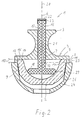
- FIG. 2 shows a longitudinal section through the instrument 1 and the insert shell 2 held by it in the positioning position on an outer shell 24.
- the sectional profile is shown in FIG. 1 as II-II. It passes through two adjacent gripping claws. 5
- the instrument 1 with the insert shell 2 held by it is placed with the end faces 11 of the claws 8 on the end face 25 of the outer shell 24.
- the insert shell 2 is positioned in the outer shell 24.
- the claws 8 overlap the outer surface 9 of the insert shell 2 in its edge region in the same length 10. This length coincides with the length of the claws 8.
- the length 10 of the claws 8 is chosen so that when their end faces 11 on the end face 25 of Outer shell 24 fully rest, no clamping contact between the outer surface 9 of the insert shell 2 and the inner surface 26 of the outer shell 24 is made.
- the plunger 16 Only by pressing the plunger 16 by a force in the direction of arrow 20, the gripping claws 5 release the insert shell 2 due to their elasticity.
- the plunger 16 carries at its end facing the insert shell 2 a plate 18 which lies on its outer periphery 27 annularly on the joint surface 19 of the insert shell 2.
- the insert shell 2 is pressed after release by the holding tool 4 in the outer shell 24. Due to the Konizticianen the outer surface 9 of the insert shell 2 and the inner surface 26 of the outer shell 24 is a press fit.
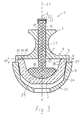
- FIG. 3 which reproduces a sectional view corresponding to FIG. 2, the plunger 16 carries at its end facing the insert shell 2 a punch head 28 adapted to the articular surface 19. Similar features are denoted by the same reference numerals in this exemplary embodiment.
- the punch head 28 has the shape of a spherical cap and its surface 29 corresponds exactly to the joint surface 19 of the insert shell 2. In this embodiment, a large-scale and uniform introduction of the force in the insert shell 2 is possible.
- the instrument 1 for handling a tray 2 may be made of a sterilizable material, for example, a heat and chemical resistant plastic or a metal having the same characteristics, so that reuse is possible.
- the instrument can also be considered as a disposable tool, which is disposed of after use. In this case, it is possible to provide an insert tray together with an instrument that already holds the insert tray with its holding tool, sterile packaged the surgeon. In order to eliminates the manual insertion of the insert shell in the holding tool of the instrument during the operation, which facilitates the working conditions of the surgeon and excludes damage to the sensitive joint surface of the insert shell.
Landscapes
- Health & Medical Sciences (AREA)
- Transplantation (AREA)
- Orthopedic Medicine & Surgery (AREA)
- Heart & Thoracic Surgery (AREA)
- Life Sciences & Earth Sciences (AREA)
- Oral & Maxillofacial Surgery (AREA)
- Engineering & Computer Science (AREA)
- Biomedical Technology (AREA)
- Physical Education & Sports Medicine (AREA)
- Vascular Medicine (AREA)
- Cardiology (AREA)
- Animal Behavior & Ethology (AREA)
- General Health & Medical Sciences (AREA)
- Public Health (AREA)
- Veterinary Medicine (AREA)
- Prostheses (AREA)
- Surgical Instruments (AREA)
- Non-Disconnectible Joints And Screw-Threaded Joints (AREA)
- Lining Or Joining Of Plastics Or The Like (AREA)
Description
- Die Erfindung betrifft ein Instrument zur Handhabung und zum Einsetzen einer Einsatzschale in eine Außenschale einer zweiteiligen Gelenkpfannen-Prothese entsprechend dem Oberbegriff des ersten Anspruchs, wie es z.B. aus der US-A-5 169 399 bekannt ist.
- Gelenk-Prothesen, bei denen ein Gelenkpartner als Pfanne und der andere Gelenkpartner als Kugelkopf ausgebildet ist, der in der Pfanne drehbar gelagert ist, sind insbesondere als Schulter- und Hüftgelenk-Prothesen bekannt. Diese Prothesen sind in der Regel modular aufgebaut. Das heißt, daß beispielsweise die Gelenkpfanne zweiteilig ist und aus einer Außenschale besteht, die in den Knochen eingesetzt wird und aus einer Einsatzschale, die in die Außenschale eingesetzt wird und die die Gelenkfläche, die Gleitfläche für den anderen Gelenkpartner, aufweist. Das Einsetzen der Einsatzschale in die Außenschale erfolgt in der Regel mittels Preßsitz. Dazu ist es notwendig, daß die Einsatzschale sehr genau zur Außenschale ausgerichtet werden muß, um beim Einsetzen ein Verkanten zu vermeiden. Beim verkanteten Einsetzen können, außer einer ungenauen Zuordnung der Gelenkfläche zum Kugelkopf, Beschädigungen an der Einsatzschale auftreten. Insbesondere Einsatzschalen aus Keramik können ausbrechen oder sogar zerbrechen.
- Werden die Einsatzschalen durch den Chirurgen mit der Hand eingesetzt, ist die Handhabung in dem Umfeld der Operationswunde aufgrund der durch Körperflüssigkeiten benetzten Handschuhe des Chirurgen und der schlechten Übersichtlichkeit schwierig. Aus diesem Grund ist es bekannt, Instrumente vorzusehen, mit der einzusetzende Einsatzschalen besser zu handhaben sein sollen. Aus dem deutschen Gebrauchsmuster DE 297 02 093 U1 ist ein Handhabungsinstrument von Gelenkkomponenten mit Gelenkflächen bekannt, das ein Griffteil und daran ein endseitig angeordnetes Saugelement aufweist, welches ein in sich geschlossenes, an die Gelenkfläche der Gelenkkomponente abdichtend anlegbares und mit dieser Gelenkfläche dadurch eine abgeschlossene Saugkammer ausbildendes Dichtelement sowie eine den Druck der Saugkammer absenkende Einrichtung umfaßt. Dieses Handhabungsinstrument wird mit dem Dichtelement auf die Gelenkfläche der einzusetzenden Einsatzschale aufgesetzt, der Druck in der Saugkammer wird erniedrigt und dadurch die Einsatzschale angesaugt. Nach dem Einsetzen der Einsatzschale wird der Druck wieder erhöht und das Handhabungsinstrument löst sich selbsttätig von der eingesetzten Einsatzschale.
- Das bekannte Handhabungsinstrument bietet aber keine Sicherheit, daß die Einsatzschale in der erforderlichen Genauigkeit auf die Außenschale aufgesetzt und dadurch ein Verkanten vermieden werden kann. Außerdem sind die bekannten Handhabungsgeräte lang (bis zu 40 cm). Sie sind dadurch unhandlich und lassen somit das erforderliche Feingefühl beim Einsetzvorgang vermissen.
- Der vorliegenden Erfindung liegt die Aufgabe zugrunde, ein Instrument zur Handhabung und zum Einsetzen einer Einsatzschale in eine Außenschale einer zweiteiligen Gelenkpfannen-Prothesen vorzustellen, mit dem ein leichtes Positionieren und ein verkantungsfreies Einsetzen möglich ist.
- Die Lösung der Aufgabe erfolgt mit Hilfe der kennzeichnenden Merkmale des ersten Anspruchs. Vorteilhafte Ausgestaltungen der Erfindung werden in den Unteransprüchen beansprucht.
- Das erfindungsgemäße Instrument zur Handhabung und zum Einsetzen einer Einsatzschale in eine Außenschale einer zweiteiligen Gelenkpfannen-Prothese besteht aus einem Griff mit einem daran anschließenden Haltewerkzeug. Durch den Griff läßt sich das Haltewerkzeug fur die Einsatzschale leicht handhaben. Das Haltewerkzeug weist mindestens zwei Greifklauen auf. Diese erstrecken sich im wesentlichen radial zur Längsachse des Griffs. Die Krallen der Greifklauen liegen auf der stirnseitigen Umfangsflache der einzusetzenden Einsatzschale auf.
- Durch die Anordnung der Greifklauen und ihrer Krallen wird die Einsatzschale genau zentrisch zur Längsachse des Griffs und senkrecht zu dieser Achse ausgerichtet gehalten. Dadurch wird für den Chirurgen eine genaue Ausrichtung der Einsatzschale beim Einsetzen möglich. Die kurze Bauart des Instruments bietet außerdem dem Chirurgen das erforderliche Feingefühl beim Einsetzvorgang.
- Die Krallen der Greifklauen umgreifen die sich verjüngende Außenfläche der Einsatzschale in jeweils gleicher Länge so weit, daß einerseits ein sicheres Halten aber auch andererseits ein leichtes Ausstoßen aus den Krallen möglich ist. Das Ausstoßen der Einsatzschale aus den Greifklauen des Haltewerkzeugs erfolgt mittels eines Stößels, der verschiebbar in einer Bohrung gelagert ist, die konzentrisch zur Längsachse des Griffs verläuft. Beim Verschieben des Stößels in Richtung auf die Einsatzschale wird diese aus den Krallen der Greifklauen herausgedrückt und kann in die Außenschale der Gelenkpfannen-Prothese eingedrückt werden.
- In einer Ausgestaltung der Erfindung weisen die Krallen der Greifklauen senkrecht zur Längsachse verlaufende Stirnflächen auf. Diese Stirnflächen dienen zum Aufsetzen auf die Stirnfläche der Außenschale. Da die Krallen an den Greifklauen alle gleich lang sind, ist beim Aufsetzen aller Klauen auf die Stirnfläche der Außenschale die Einsatzschale für ihren Einsatz genau positioniert. Diese Ausgestaltung der Greifklauen ist ein vorteilhaftes Hilfsmittel für den Chirurgen, mit dem er in dem schwierigen Umfeld der Operationswunde die Einsatzschale sicher und genau für den Einsatz positionieren kann.
- Damit bei der Positionierung des Instruments mit der Einsatzschale auf der Außenschale keine Beeinträchtigung der Lage der Einsatzschale erfolgt, ist die Länge der Krallen mindestens so bemessen, daß bei ihrem Aufsetzen auf die Stirnfläche der Außenschale die von ihnen gehaltene Einsatzschale noch keinen Klemmkontakt mit der Außenschale hat. Damit ist ein Korrektur der Positionierung jeder Zeit möglich. Diese ist abgeschlossen, wenn alle Klauen mit ihren Stirnflächen auf der Stirnfläche der Außenschale aufliegen.
- In weiterer Ausgestaltung der Erfindung sind die Klauen aus einem elastischen Werkstoff, damit die gehaltene Einsatzschale leicht aus dem Haltewerkzeug herausdrückbar ist. Ein weiterer Vorteil besteht darin, daß Einsatzschalen, die sich in ihren Durchmessern nur geringfügig unterscheiden, von ein und dem selben Haltewerkzeug gehalten werden können.
- In einer anderen Ausgestaltung der Erfindung sind die Krallen der Greifklauen aus einem elastischen Werkstoff gefertigt. Insbesondere bei Instrumenten, die nur einmal benutzt werden, können die Krallen so ausgebildet sein, daß sie sich beim Herausdrücken der Einsatzschale aus den Greifklauen sogar bleibend verformen.
- In weiterer vorteilhafter Ausgestaltung der Erfindung weist der Griff eine Griffmulde auf. Diese Griffmulde ermöglichst beispielsweise die Klemmung des Griffs zwischen zwei parallelen Fingern, beispielsweise dem Mittel- und dem Ringfinger oder dem Zeige- und dem Mittelfinger. Die Griffmulde kann beispielsweise U-förmig sein und um den gesamten Griff laufen, so daß eine optimale Lagerung des Instruments in der Hand des Chirurgen in jeder möglichen Ausrichtung möglich ist. Das Ausdrücken der Einsatzschale kann dann beispielsweise mittels des Daumens oder des Handballens erfolgen.
- Damit der Stößel beim Ausstoßen der Einsatzschale aus den Greifklauen keine punktuelle Belastung auf die Einsatzschale ausübt, ist es vorteilhaft, wenn sein Ende mindestens eine Platte aufweist, mit der er sich ringförmig auf die Einsatzschale abstützt. Eine solche Platte hat den Vorteil, daß der Stößel für Einsatzschalen mit unterschiedlichen Gelenkflächendurchmessern einsetzbar ist.
- In einer anderen Ausgestaltung der Erfindung weist der Stößel an seinem Ende einen der Gelenkfläche der Einsatzschale angepaßten Stempelkopf auf. Der Stempelkopf hat dann die Form einer Kugelkalotte, deren Radius dem Radius der Gelenkfläche entspricht. Ein solcher Stößel ist zwar nur für einen Durchmesser einer Einsatzschale einsetzbar, weist aber den Vorteil auf, daß er die beim Einsetzen aufzubringende Kraft großflächig und gleichmäßig auf die Einsatzschale verteilt.
- Das Einpressen der Einsatzschale in die Außenschale erfolgt in der Regel durch den Chirurgen manuell. Zur endgültigen Fixierung kann allerdings noch ein nachträglicher Schlag mit einem Schlagwerkzeug erforderlich sein. In einem solchen Fall bietet auch das erfindungsgemäße Instrument eine Möglichkeit, einen solchen Fixierungsschlag gezielt auf die Einsatzschale aufzubringen. Durch die genaue Ausrichtung des Instruments zur Außenschale und damit der Einsatzschale zur Außenschale werden die durch den Schlag aufgebrachten Kräfte gleichmäßig und ihrem Zweck entsprechend genau in die Einsatzschale eingeleitet.
- Anhand eines Ausführungsbeispiels wird die Erfindung näher erläutert.
- Es zeigen:
- Figur 1
- das erfindungsgemäße Instrument mit einer einzusetzenden Einsatzschale im Haltewerkzeug,
- Figur 2
- einen Schnitt längs der Achse durch den Griff des Instruments, wie in der Figur eingezeichnet, und
- Figur 3
- ein Schnittbild entsprechend Figur 2 mit einer weiteren Ausgestaltung des Stößels.
- Die Darstellung in den Figuren erfolgt in vergrößertem Maßstab. In Figur 1 ist mit 1 das erfindungsgemäße Instrument zur Handhabung und zum Einsetzen der von ihm gehaltenen Einsatzschale 2 bezeichnet. Das Instrument 1 besteht aus einem-Griff 3 und einem Haltewerkzeug 4. Das Haltewerkzeug 4 weist im vorliegenden Ausführungsbeispiel drei Greifklauen 5 auf, die sich im wesentlichen radial von der Längsachse 6 des Griffs 3 aus erstrecken. Im Schnittbild der Figur 2 ist das anhand des rechten Winkels 7 ersichtlich. Die Greifklauen sind im vorliegenden Ausführungsbeispiel in gleichen Winkelabständen → angeordnet, was aber nicht zwingend erforderlich ist.
- Die Greifklauen 5 weisen Kralle 8 auf, die die sich verjüngende Außenfläche 9 der Einsatzschale 2 übergreifen. Um der Konizität der Außenfläche 9 der Einsatzschale 2 Rechnung zu tragen, weisen die Krallen 8 jeweils eine Hinterschneidung 13 auf. Die Krallen 8 weisen alle die gleiche Länge 10 auf. Damit eine genaue Positionierung und Ausrichtung der Einsatzschale 2 zur Außenschale möglich ist, stehen die Anlageflächen 14 der Greifklauen 5, die auf der Stirnseite 15 der Einsatzschale 2 liegen, senkrecht zur Längsachse 6 des Griffs 3. Ihre Verlängerung schneidet die Achse 6 im rechten Winkel 7, wie in Figur 2 dargestellt. Das ermöglicht eine genaue Anlage des Instruments an die Stirnfläche der Außenschale, wie aus der Figur 2 ersichtlich ist.
- Im vorliegenden Ausführungsbeispiel sind die Greifklauen 5 elastisch, so daß bei einem Druck auf die Einsatzschale 2 in Richtung aus dem Instrument 1 heraus die Krallen 8 nach außen gebogen werden und die Einsatzschale 2 freigeben.
- Das Ausdrücken der Einsatzschale 2 aus dem Haltewerkzeug 4 erfolgt mittels eines Stößels 16. Der Stößel 16 ist in einer Bohrung 17 gelagert, die konzentrisch zur Längsachse 6 im Griff 3 verläuft. An seinem, der Einsatzschale 2 zugewandten Ende trägt der Stößel 16 im vorliegenden Ausführungsbeispiel eine Platte 18. Diese liegt mit ihrem äußeren Umfang 27 ringförmig an der Gelenkfläche 19 der Einsatzschale 2 an. Die Anlagefläche liegt konzentrisch zur Längsachse 6 des Griffs 3, wie aus der Figur 2 ersichtlich. Dadurch wird eine gleichmäßige Einleitung der Druckkraft in die Einsatzschale 2 gewährleistet. Wird auf den Stößel 16 in Pfeilrichtung 20 eine Kraft ausgeübt, so geben die Greifklauen 5 aufgrund ihrer Elastizität die Einsatzschale 2 frei.
- Der Griff 3 besitzt eine U-förmige Griffmulde 21, die zentrisch um den Griff umläuft. Sie ist so gestaltet, daß der Griff insbesondere zwischen zwei parallel verlaufende Finger gehalten werden kann. Dann ist es möglich, mittels des Handballens oder mit dem Daumen auf die Stirnfläche 22 des Stößels 16 zu drücken und die Einsatzschale 2 aus dem Haltewerkzeug 4 herauszudrücken. Eine Kappe 23 auf der Stirnfläche 22 des Stößels 16 besitzt einen solchen Durchmesser, daß der Stößel nicht durch die Bohrung 17 hindurchgleiten kann, wenn die Einsatzschale 2 in die Außenschale gedrückt wird. Außerdem schützt diese Kappe 23 den Schaft 22 bei eventuellen Schlägen mit einem Schlagwerkzeug und verhindert so ein Abplatzen oder Absplittern der Stirnseitenkanten des Stößels 16.
- Figur 2 zeigt einen Längsschnitt durch das Instrument 1 und der von ihr gehaltenen Einsatzschale 2 in der Positionierposition auf einer Außenschale 24. Der Schnittverlauf ist in Figur 1 mit II-II eingezeichnet. Er verläuft durch zwei benachbarte Greifklauen 5.
- In Figur 2 ist das Instrument 1 mit der von ihm gehaltenen Einsatzschale 2 mit den Stirnflächen 11 der Krallen 8 auf die Stirnfläche 25 der Außenschale 24 aufgesetzt. Die Einsatzschale 2 ist in der Außenschale 24 positioniert. Beim Aufsetzen aller Stirnflächen 11 der Krallen 8 auf die Stirnfläche 25 der Außenschale 24 ist eine genaue Zentrierung und Positionierung der Einsatzschale 2 gewährleistet.
- Wie aus dem Schnittbild ersichtlich, ubergreifen die Krallen 8 die Außenfläche 9 der Einsatzschale 2 in ihrem Randbereich in gleicher Länge 10. Diese Länge stimmt mit der Länge der Krallen 8 überein. Die Länge 10 der Krallen 8 ist so gewählt, daß dann, wenn ihre Stirnflächen 11 auf der Stirnfläche 25 der Außenschale 24 vollständig aufliegen, noch kein Klemmkontakt zwischen der Außenfläche 9 der Einsatzschale 2 und der Innenfläche 26 der Außenschale 24 besteht.
- Erst durch Betätigung des Stößels 16 durch eine Krafteinwirkung in Pfeilrichtung 20 werden die Greifklauen 5 aufgrund ihrer Elastizität die Einsatzschale 2 freigeben. Im vorliegenden Ausführungsbeispiel trägt der Stößel 16 an seinem der Einsatzschale 2 zugewandten Ende eine Platte 18, die auf ihrem äußeren Umfang 27 ringförmig auf der Gelenkfläche 19 der Einsatzschale 2 liegt. Durch eine Krafteinwirkung in Pfeilrichtung 20 auf den Stößel 16 wird die Einsatzschale 2 nach Freigabe durch das Haltewerkzeug 4 in die Außenschale 24 gepreßt. Aufgrund der Konizitäten der Außenfläche 9 der Einsatzschale 2 und der Innenfläche 26 der Außenschale 24 erfolgt ein Preßsitz.
- In Figur 3, das ein der Figur 2 entsprechendes Schnittbild wiedergibt, trägt der Stößel 16 an seinem, der Einsatzschale 2 zugewandten Ende einen der Gelenkfläche 19 angepaßten Stempelkopf 28. Gleichartige Merkmale sind in diesem Ausführungsbeispiel mit denselben Bezugszeichen bezeichnet. Der Stempelkopf 28 hat die Form einer Kugelkalotte und seine Oberfläche 29 entspricht genau der der Gelenkfläche 19 der Einsatzschale 2. Bei dieser Ausführungsform ist eine großflächige und gleichmäßige Einleitung der Kraft in die Einsatzschale 2 möglich.
- Das Instrument 1 zur Handhabung einer Einsatzschale 2 kann aus einem sterilisierbaren Material hergestellt werden, beispielsweise aus einem hitze- und chemikalienresistenten Kunststoff oder aus einem Metall mit gleichen Eigenschaften, so daß eine Wiederverwendung möglich ist. Das Instrument kann aber auch als ein Einmalwerkzeug angesehen werden, das nach seiner Verwendung entsorgt wird. In diesem Fall ist es möglich, eine Einsatzschale zusammen mit einem Instrument, das die Einsatzschale bereits mit seinem Haltewerkzeug hält, steril verpackt dem Chirurgen zur Verfügung zu stellen. Damit entfällt das manuelle Einsetzen der Einsatzschale in das Haltewerkzeug des Instruments während der Operation, was die Arbeitsbedingungen des Chirurgen erleichtert und Beschädigungen der empfindlichen Gelenkfläche der Einsatzschale ausschließt.
Claims (9)
- Instrument zur Handhabung und zum Einsetzen einer Einsatzschale in eine Außenschale einer zweiteiligen Gelenkpfannen-Prothese mit einem Haltewerkzeug zum lösbaren Halten der einzusetzenden Einsatzschale, wobei das Instrument (1) aus einem Griff (3) und einem sich daran anschließenden Haltewerkzeug (4) besteht, und das Haltewerkzeug (4) mindestens zwei Greifklauen (5) aufweist, die sich im wesentlichen radial (7) von der Längsachse (6) des Griffs (3) erstrecken, dadurch gekennzeichnet, daß die Greifklauen (5) dazu geeignet sind, auf der Stirnfläche (15) der Einsatzschale (2) aufzuliegen, daß die Greifklauen (5) Krallen (8) aufweisen, die dazu geeignet sind, die sich verjüngende Außenfläche (9) der Einsatzschale (2) in jeweils gleicher Länge (10) so weit zu übergreifen, daß eine Freigabe der Einsatzschale (2) bei einer auf ihr ausgeübten Druckkraft erfolgt, daß durch den Griff (3) konzentrisch zu seiner Längsachse (6) eine Bohrung (17) verläuft, in der ein aus dem Griff (3) herausragender Stößel (16) verschiebbar gelagert ist, und daß beim Verschieben des Stößels (16) in Richtung (20) auf die Einsatzschale (2) diese aus dem Haltewerkzeug (4) herausdrückbar ist.
- Instrument nach Anspruch 1, dadurch gekennzeichnet, daß die Krallen (8) der Greifklauen (5) des Haltewerkzeugs (4) senkrecht (12) zur Längsachse (6) des Griffs (3) verlaufende Stirnflächen (11) zum Aufsetzen auf die Stirnfläche (25) der Außenschale (24) aufweisen.
- Instrument nach Anspruch 1 oder 2 in Kombination mit einer Einsatzschale und einer Außenschale, dadurch gekennzeichnet, daß die Länge (10) der Krallen (8) mindestens so bemessen ist, daß beim Aufsetzen der Einrichtung (1) auf die Stirnfläche (25) der Außenschale (24) die konische Außenfläche (9) der Einsatzschale (2) noch keinen Klemmkontakt mit der Innenfläche (26) der Außenschale (24) hat.
- Instrument nach einem der Ansprüche 1 bis 3, dadurch gekennzeichnet, daß die Greifklauen (5) des Haltewerkzeugs (4) aus einem elastischen Werkstoff bestehen.
- Instrument nach einem der Ansprüche 1 bis 3, dadurch gekennzeichnet, daß die Krallen (8) der Greifklauen (5) des Haltewerkzeugs (4) aus einem elastischen Werkstoff bestehen.
- Instrument nach einem der Ansprüche 1 bis 5, dadurch gekennzeichnet, daß der Griff (3) des Instruments (1) eine Griffmulde (21) aufweist.
- Instrument nach Anspruch 6, dadurch gekennzeichnet, daß die Griffmulde (21) U-förmig und umlaufend ist.
- Instrument nach einem der Ansprüche 1 bis 7, dadurch gekennzeichnet, daß der Stößel (16) an seinem der Einsatzschale (2) zugewandten Ende eine Platte (18) aufweist, die mit ihrem äußeren Umfang (27) konzentrisch an der Gelenkfläche (19) der Einsatzschale (2) anlegbar ist.
- Instrument nach einem der Ansprüche 1 bis 8, dadurch gekennzeichnet, daß der Stößel (16) an seinem der Einsatzschale (2) zugewandtem Ende einen der Gelenkfläche (19) angepaßten Stempelkopf (28) trägt.
Applications Claiming Priority (5)
| Application Number | Priority Date | Filing Date | Title |
|---|---|---|---|
| DE19819193 | 1998-04-30 | ||
| DE19819193 | 1998-04-30 | ||
| DE19820721A DE19820721A1 (de) | 1998-04-30 | 1998-05-11 | Instrument zur Handhabung von Komponenten von Gelenkprothesen |
| DE19820721 | 1998-05-11 | ||
| PCT/EP1999/002933 WO1999056677A1 (de) | 1998-04-30 | 1999-04-29 | Instrument zur handhabung von komponenten von gelenkprothesen |
Publications (2)
| Publication Number | Publication Date |
|---|---|
| EP1076537A1 EP1076537A1 (de) | 2001-02-21 |
| EP1076537B1 true EP1076537B1 (de) | 2006-10-11 |
Family
ID=26045850
Family Applications (1)
| Application Number | Title | Priority Date | Filing Date |
|---|---|---|---|
| EP99923501A Expired - Lifetime EP1076537B1 (de) | 1998-04-30 | 1999-04-29 | Instrument zur handhabung von komponenten von gelenkprothesen |
Country Status (6)
| Country | Link |
|---|---|
| US (1) | US6468281B1 (de) |
| EP (1) | EP1076537B1 (de) |
| JP (1) | JP4073626B2 (de) |
| AT (1) | ATE342022T1 (de) |
| DE (1) | DE59913912D1 (de) |
| WO (1) | WO1999056677A1 (de) |
Cited By (2)
| Publication number | Priority date | Publication date | Assignee | Title |
|---|---|---|---|---|
| WO2010069940A1 (de) * | 2008-12-17 | 2010-06-24 | Ceramtec Ag | Einsetzinstrument zum einsetzen von pfanneneinsätzen in die kalotten von hüftpfannen |
| WO2011161166A1 (de) | 2010-06-25 | 2011-12-29 | Ceramtec Gmbh | Einsetzinstrument zum einsetzen von pfanneneinsätzen in hüftpfannen für die hüftendoprothetik |
Families Citing this family (40)
| Publication number | Priority date | Publication date | Assignee | Title |
|---|---|---|---|---|
| DE19926923A1 (de) * | 1999-06-14 | 2000-12-21 | Ceramtec Ag | Modular aufgebaute Gelenkpfanne für eine Kugelgelenk-Prothese |
| US20020120340A1 (en) | 2001-02-23 | 2002-08-29 | Metzger Robert G. | Knee joint prosthesis |
| US7497874B1 (en) | 2001-02-23 | 2009-03-03 | Biomet Manufacturing Corp. | Knee joint prosthesis |
| US20050137603A1 (en) * | 2003-11-12 | 2005-06-23 | Kevin Belew | Acetabular cup positioning instrument |
| US20050171545A1 (en) * | 2004-01-30 | 2005-08-04 | Howmedica Osteonics Corp. | Knee computer-aided navigation instruments |
| GB0405059D0 (en) * | 2004-03-05 | 2004-04-07 | Benoist Girard Sas | Prosthetic acetabular cup inserter |
| US20050228394A1 (en) * | 2004-03-31 | 2005-10-13 | Diane Bihary | Suction inserter |
| FR2876278B1 (fr) | 2004-10-13 | 2007-10-26 | Thomas Gradel | Instruments de pose de cotyle |
| US8147547B2 (en) * | 2005-04-29 | 2012-04-03 | Warsaw Orthopedic, Inc. | Spinal implant |
| US7727282B2 (en) | 2006-03-17 | 2010-06-01 | Biomet Manufacturing Corp. | Method and apparatus for implanting a prosthesis |
| US20080133023A1 (en) * | 2006-10-05 | 2008-06-05 | Zimmer Technology, Inc. | Provisional prosthetic component formed of multiple materials |
| US8328873B2 (en) | 2007-01-10 | 2012-12-11 | Biomet Manufacturing Corp. | Knee joint prosthesis system and method for implantation |
| US8157869B2 (en) | 2007-01-10 | 2012-04-17 | Biomet Manufacturing Corp. | Knee joint prosthesis system and method for implantation |
| US8163028B2 (en) | 2007-01-10 | 2012-04-24 | Biomet Manufacturing Corp. | Knee joint prosthesis system and method for implantation |
| US8562616B2 (en) | 2007-10-10 | 2013-10-22 | Biomet Manufacturing, Llc | Knee joint prosthesis system and method for implantation |
| US8187280B2 (en) | 2007-10-10 | 2012-05-29 | Biomet Manufacturing Corp. | Knee joint prosthesis system and method for implantation |
| JP2010519972A (ja) * | 2007-02-28 | 2010-06-10 | スミス アンド ネフュー インコーポレーテッド | 寛骨臼ライナーインサーターガイド |
| US20080269765A1 (en) * | 2007-04-27 | 2008-10-30 | Zimmer, Inc. | Instrument and method for implanting a prosthetic component |
| US8123815B2 (en) | 2008-11-24 | 2012-02-28 | Biomet Manufacturing Corp. | Multiple bearing acetabular prosthesis |
| US10420648B2 (en) * | 2009-06-10 | 2019-09-24 | Jean-Pierre LAFFAY | Acetabular prosthetic system with simplified impaction |
| US8308810B2 (en) | 2009-07-14 | 2012-11-13 | Biomet Manufacturing Corp. | Multiple bearing acetabular prosthesis |
| US8679130B2 (en) * | 2010-03-05 | 2014-03-25 | Biomet Manufacturing, Llc | Guide assembly for lateral implants and associated methods |
| US8221432B2 (en) | 2010-03-05 | 2012-07-17 | Biomet Manufacturing Corp. | Method and apparatus for implanting a modular femoral hip |
| US8529569B2 (en) | 2010-03-05 | 2013-09-10 | Biomet Manufacturing, Llc | Method and apparatus for preparing a proximal femur |
| US8419743B2 (en) | 2010-03-05 | 2013-04-16 | Biomet Manufacturing Corp. | Assembly tool for modular implants and associated method |
| US8460393B2 (en) * | 2010-03-05 | 2013-06-11 | Biomet Manufacturing Corp. | Modular lateral hip augments |
| US8333807B2 (en) * | 2010-03-05 | 2012-12-18 | Biomet Manufacturing Corp. | Method and apparatus for trialing and implanting a modular femoral hip |
| FR2961387B1 (fr) * | 2010-06-17 | 2013-06-07 | Thomas Gradel | Cotyle ceramique a fixation externe |
| US20150094728A1 (en) * | 2013-09-30 | 2015-04-02 | DePuy Synthes Products, LLC | Instrument for positioning a cup component of an orthopaedic joint prosthesis |
| GB201317287D0 (en) | 2013-09-30 | 2013-11-13 | Depuy Ireland Ltd | An instrument for positioning a cup component of an orthopaedic joint prosthesis |
| US20150230926A1 (en) | 2014-02-18 | 2015-08-20 | Biomet Manufacturing, Llc | Method and device for reducing implant contamination from handling |
| FR3018188B1 (fr) | 2014-03-07 | 2016-02-26 | Xnov Ip | Dispositif pour prendre et inserer un element insert |
| FR3028173B1 (fr) * | 2014-11-07 | 2016-12-09 | Soc D'etudes De Rech Et De Fabrication (Serf) | Instrument pour le montage d’un insert dans une cupule et ensemble pour la mise en place d’une prothese de hanche sur un patient |
| FR3028174B1 (fr) * | 2014-11-07 | 2022-07-01 | Dedienne Sante | Ensemble pour l'implantation d'un cotyle |
| GB201507211D0 (en) * | 2015-04-28 | 2015-06-10 | Depuy Ireland | Device and method for inserting a liner into an acetabular cup |
| EP3231398B1 (de) | 2016-04-12 | 2018-09-26 | Dedienne Sante | Einheit zur implantation einer gelenkpfanne in einen gelenkpfannenhohlraum |
| US10245161B2 (en) | 2016-07-12 | 2019-04-02 | Dedienne Sante | Assembly for implanting an acetabular cup in a cotyloid cavity |
| US10709581B2 (en) * | 2016-08-17 | 2020-07-14 | Joint Innovation Technology Llc | Thermally securing Morse taper |
| US10588756B2 (en) | 2017-03-31 | 2020-03-17 | DePuy Synthes Products, Inc. | System and method for implanting an acetabular prosthetic component |
| US10596011B2 (en) | 2018-01-31 | 2020-03-24 | Depuy Ireland Unlimited Company | Orthopaedic surgical instrument and method for positioning an acetabular prosthetic component |
Family Cites Families (9)
| Publication number | Priority date | Publication date | Assignee | Title |
|---|---|---|---|---|
| FR2639824B1 (fr) * | 1988-12-07 | 1991-03-29 | Implants Instr Ch Fab | Appareil pour la pose d'un element de prothese |
| US5098437A (en) | 1991-02-13 | 1992-03-24 | Pfizer Hospital Products Group, Inc. | Acetabular cup positioning insert |
| US5169399A (en) * | 1991-10-17 | 1992-12-08 | Boehringer Mannheim Corporation | Acetabular cup impactor |
| FR2701206A1 (fr) | 1993-02-09 | 1994-08-12 | Medinov Sa | Appareil impacteur d'un noyau ou d'une cupule en polyéthylène pour implant cotyloïdien. |
| US5571111A (en) | 1995-05-01 | 1996-11-05 | Aboczky; Robert I. | Instrument for orienting, inserting and impacting an acetabular cup prosthesis including prosthesis retaining head arrangement |
| DE19611249A1 (de) | 1996-03-22 | 1997-09-25 | Cerasiv Gmbh | Kombination aus einer Gelenkprothese und einem Ausziehwerkzeug |
| DE19628193C2 (de) | 1996-07-12 | 1998-06-04 | Eska Implants Gmbh & Co | Beckenpfannen-Setzinstrument |
| DE19722923B4 (de) | 1997-02-06 | 2008-04-10 | Ceramtec Ag Innovative Ceramic Engineering | Werkzeug zum Einsetzen einer keramischen Einsatzschale in eine metallische Außenschale einer zweiteiligen Gelenkpfannen-Prothese |
| EP0888759B1 (de) * | 1997-07-04 | 2003-01-02 | Sulzer Orthopädie AG | Instrument zum Einbringen eines Einsatzes eines Implantats in die zugehörige Schale |
-
1999
- 1999-04-29 EP EP99923501A patent/EP1076537B1/de not_active Expired - Lifetime
- 1999-04-29 WO PCT/EP1999/002933 patent/WO1999056677A1/de not_active Ceased
- 1999-04-29 JP JP2000546710A patent/JP4073626B2/ja not_active Expired - Fee Related
- 1999-04-29 US US09/673,541 patent/US6468281B1/en not_active Expired - Lifetime
- 1999-04-29 DE DE59913912T patent/DE59913912D1/de not_active Expired - Lifetime
- 1999-04-29 AT AT99923501T patent/ATE342022T1/de active
Cited By (4)
| Publication number | Priority date | Publication date | Assignee | Title |
|---|---|---|---|---|
| WO2010069940A1 (de) * | 2008-12-17 | 2010-06-24 | Ceramtec Ag | Einsetzinstrument zum einsetzen von pfanneneinsätzen in die kalotten von hüftpfannen |
| DE102009054633A1 (de) | 2008-12-17 | 2010-06-24 | Ceramtec Ag | Einsetzinstrument zum Einsetzen von Pfanneneinsätzen in die Kalotten von Hüftpfannen |
| WO2011161166A1 (de) | 2010-06-25 | 2011-12-29 | Ceramtec Gmbh | Einsetzinstrument zum einsetzen von pfanneneinsätzen in hüftpfannen für die hüftendoprothetik |
| DE102011077992A1 (de) | 2010-06-25 | 2012-06-14 | Ceramtec Gmbh | Einsetzinstrument zum Einsetzen von Pfanneneinsätzen in Hüftpfannen für die Hüftendoprothetik |
Also Published As
| Publication number | Publication date |
|---|---|
| ATE342022T1 (de) | 2006-11-15 |
| WO1999056677A1 (de) | 1999-11-11 |
| JP2002513631A (ja) | 2002-05-14 |
| US6468281B1 (en) | 2002-10-22 |
| EP1076537A1 (de) | 2001-02-21 |
| JP4073626B2 (ja) | 2008-04-09 |
| DE59913912D1 (de) | 2006-11-23 |
Similar Documents
| Publication | Publication Date | Title |
|---|---|---|
| EP1076537A1 (de) | Instrument zur handhabung von komponenten von gelenkprothesen | |
| EP2349117B1 (de) | Instrument zur handhabung einer gelenkkomponente mittels unterdruck | |
| DE68913927T2 (de) | Vorrichtung für das Einsetzen eines Femoralkopfes. | |
| DE19813328A1 (de) | Einrichtung zur Handhabung von Kugelköpfen von Gelenk-Prothesen | |
| EP2497432B1 (de) | Medizinisches Einstechwerkzeug | |
| DE60210735T2 (de) | Transfervorrichtung sowie System mit einer Kappenanordnung, einem Behälter und der Transfervorrichtung | |
| DE2838348C2 (de) | Vorrichtung zum Ausformen einer Knochenöffnung | |
| DE69631344T2 (de) | Bohrlehre instrument | |
| DE4300039C1 (de) | Befestigungsnagel und Setzwerkzeug hierfür | |
| EP0281763B1 (de) | Hilfsinstrument zum Setzen von Löchern beim Implantieren von Verriegelungsnägeln | |
| EP1463466A2 (de) | Hilfsmittel zur implantation einer hüftgelenkendoprothese sowie verfahren für handhabung desselben | |
| DE69808703T2 (de) | Apparat zum Verdichten von Knochenspänen in einem Knochenkanal | |
| EP1721583A2 (de) | Implantat zum Einsetzen zwischen Wirbelkörper sowie Operationsinstrument zum Betätigen des Implantats | |
| DE9490464U1 (de) | Hüftgelenkspfannen-Positionierwerkzeug | |
| DE19722923B4 (de) | Werkzeug zum Einsetzen einer keramischen Einsatzschale in eine metallische Außenschale einer zweiteiligen Gelenkpfannen-Prothese | |
| EP0450007B1 (de) | Vorrichtung zum halten von prothesen für die im- und explantation der prothese | |
| DE19820721A1 (de) | Instrument zur Handhabung von Komponenten von Gelenkprothesen | |
| DE10215751A1 (de) | Vorrichtung zur Implantierung von Markierungskörpern und Magazin mit Markierungskörpern für diese Vorrichtung | |
| DE29702093U1 (de) | Handhabungsinstrument von Gelenkkomponenten mit Gelenkflächen | |
| DE4216254C2 (de) | Lichtleiter für ein Bestrahlungsgerät | |
| DE19742535C2 (de) | Chirurgische Vorrichtung zum Herausschneiden einer Schädelplatte aus dem Schädelknochen | |
| DE3613762A1 (de) | Applikationsvorrichtung von injektionsgut, insbesondere zur instrumentellen besamung oder embryouebertragung | |
| DE10151816B4 (de) | Hülsenförmige Druck- oder Übertragungsform und Gerät zum Anfasen der Längenenden einer hülsenförmigen Druck- oder Übertragungsform | |
| DE19708604C1 (de) | Chirurgisches Instrument | |
| DE29922792U1 (de) | Instrument zur Handhabung und zum Einsetzen einer Prothesenkomponente |
Legal Events
| Date | Code | Title | Description |
|---|---|---|---|
| PUAI | Public reference made under article 153(3) epc to a published international application that has entered the european phase |
Free format text: ORIGINAL CODE: 0009012 |
|
| 17P | Request for examination filed |
Effective date: 20001130 |
|
| AK | Designated contracting states |
Kind code of ref document: A1 Designated state(s): AT BE CH CY DE DK ES FI FR GB GR IE IT LI LU MC NL PT SE |
|
| GRAP | Despatch of communication of intention to grant a patent |
Free format text: ORIGINAL CODE: EPIDOSNIGR1 |
|
| GRAS | Grant fee paid |
Free format text: ORIGINAL CODE: EPIDOSNIGR3 |
|
| GRAA | (expected) grant |
Free format text: ORIGINAL CODE: 0009210 |
|
| AK | Designated contracting states |
Kind code of ref document: B1 Designated state(s): AT BE CH CY DE DK ES FI FR GB GR IE IT LI LU MC NL PT SE |
|
| PG25 | Lapsed in a contracting state [announced via postgrant information from national office to epo] |
Ref country code: NL Free format text: LAPSE BECAUSE OF FAILURE TO SUBMIT A TRANSLATION OF THE DESCRIPTION OR TO PAY THE FEE WITHIN THE PRESCRIBED TIME-LIMIT Effective date: 20061011 Ref country code: IE Free format text: LAPSE BECAUSE OF FAILURE TO SUBMIT A TRANSLATION OF THE DESCRIPTION OR TO PAY THE FEE WITHIN THE PRESCRIBED TIME-LIMIT Effective date: 20061011 Ref country code: FI Free format text: LAPSE BECAUSE OF FAILURE TO SUBMIT A TRANSLATION OF THE DESCRIPTION OR TO PAY THE FEE WITHIN THE PRESCRIBED TIME-LIMIT Effective date: 20061011 |
|
| REG | Reference to a national code |
Ref country code: GB Ref legal event code: FG4D Free format text: NOT ENGLISH |
|
| REG | Reference to a national code |
Ref country code: CH Ref legal event code: EP |
|
| REG | Reference to a national code |
Ref country code: IE Ref legal event code: FG4D Free format text: LANGUAGE OF EP DOCUMENT: GERMAN |
|
| REF | Corresponds to: |
Ref document number: 59913912 Country of ref document: DE Date of ref document: 20061123 Kind code of ref document: P |
|
| PG25 | Lapsed in a contracting state [announced via postgrant information from national office to epo] |
Ref country code: SE Free format text: LAPSE BECAUSE OF FAILURE TO SUBMIT A TRANSLATION OF THE DESCRIPTION OR TO PAY THE FEE WITHIN THE PRESCRIBED TIME-LIMIT Effective date: 20070111 Ref country code: DK Free format text: LAPSE BECAUSE OF FAILURE TO SUBMIT A TRANSLATION OF THE DESCRIPTION OR TO PAY THE FEE WITHIN THE PRESCRIBED TIME-LIMIT Effective date: 20070111 |
|
| PG25 | Lapsed in a contracting state [announced via postgrant information from national office to epo] |
Ref country code: ES Free format text: LAPSE BECAUSE OF FAILURE TO SUBMIT A TRANSLATION OF THE DESCRIPTION OR TO PAY THE FEE WITHIN THE PRESCRIBED TIME-LIMIT Effective date: 20070122 |
|
| REG | Reference to a national code |
Ref country code: CH Ref legal event code: NV Representative=s name: ISLER & PEDRAZZINI AG |
|
| PG25 | Lapsed in a contracting state [announced via postgrant information from national office to epo] |
Ref country code: PT Free format text: LAPSE BECAUSE OF FAILURE TO SUBMIT A TRANSLATION OF THE DESCRIPTION OR TO PAY THE FEE WITHIN THE PRESCRIBED TIME-LIMIT Effective date: 20070319 |
|
| NLV1 | Nl: lapsed or annulled due to failure to fulfill the requirements of art. 29p and 29m of the patents act | ||
| GBV | Gb: ep patent (uk) treated as always having been void in accordance with gb section 77(7)/1977 [no translation filed] |
Effective date: 20061011 |
|
| ET | Fr: translation filed | ||
| REG | Reference to a national code |
Ref country code: IE Ref legal event code: FD4D |
|
| PLBE | No opposition filed within time limit |
Free format text: ORIGINAL CODE: 0009261 |
|
| STAA | Information on the status of an ep patent application or granted ep patent |
Free format text: STATUS: NO OPPOSITION FILED WITHIN TIME LIMIT |
|
| REG | Reference to a national code |
Ref country code: CH Ref legal event code: PCAR Free format text: ISLER & PEDRAZZINI AG;POSTFACH 1772;8027 ZUERICH (CH) |
|
| 26N | No opposition filed |
Effective date: 20070712 |
|
| PG25 | Lapsed in a contracting state [announced via postgrant information from national office to epo] |
Ref country code: GB Free format text: LAPSE BECAUSE OF FAILURE TO SUBMIT A TRANSLATION OF THE DESCRIPTION OR TO PAY THE FEE WITHIN THE PRESCRIBED TIME-LIMIT Effective date: 20061011 |
|
| BERE | Be: lapsed |
Owner name: CERAMTEC A.G. INNOVATIVE CERAMIC ENGINEERING Effective date: 20070430 |
|
| PG25 | Lapsed in a contracting state [announced via postgrant information from national office to epo] |
Ref country code: BE Free format text: LAPSE BECAUSE OF NON-PAYMENT OF DUE FEES Effective date: 20070430 |
|
| PG25 | Lapsed in a contracting state [announced via postgrant information from national office to epo] |
Ref country code: GR Free format text: LAPSE BECAUSE OF FAILURE TO SUBMIT A TRANSLATION OF THE DESCRIPTION OR TO PAY THE FEE WITHIN THE PRESCRIBED TIME-LIMIT Effective date: 20070112 |
|
| PG25 | Lapsed in a contracting state [announced via postgrant information from national office to epo] |
Ref country code: MC Free format text: LAPSE BECAUSE OF NON-PAYMENT OF DUE FEES Effective date: 20070430 |
|
| PG25 | Lapsed in a contracting state [announced via postgrant information from national office to epo] |
Ref country code: LU Free format text: LAPSE BECAUSE OF NON-PAYMENT OF DUE FEES Effective date: 20070429 Ref country code: CY Free format text: LAPSE BECAUSE OF FAILURE TO SUBMIT A TRANSLATION OF THE DESCRIPTION OR TO PAY THE FEE WITHIN THE PRESCRIBED TIME-LIMIT Effective date: 20061011 |
|
| REG | Reference to a national code |
Ref country code: DE Ref legal event code: R081 Ref document number: 59913912 Country of ref document: DE Owner name: CERAMTEC GMBH, DE Free format text: FORMER OWNER: CERAMTEC AG, 73207 PLOCHINGEN, DE Effective date: 20110216 |
|
| PGFP | Annual fee paid to national office [announced via postgrant information from national office to epo] |
Ref country code: AT Payment date: 20140411 Year of fee payment: 16 |
|
| REG | Reference to a national code |
Ref country code: FR Ref legal event code: PLFP Year of fee payment: 17 |
|
| PGFP | Annual fee paid to national office [announced via postgrant information from national office to epo] |
Ref country code: DE Payment date: 20150625 Year of fee payment: 17 Ref country code: CH Payment date: 20150420 Year of fee payment: 17 |
|
| PGFP | Annual fee paid to national office [announced via postgrant information from national office to epo] |
Ref country code: FR Payment date: 20150421 Year of fee payment: 17 Ref country code: IT Payment date: 20150430 Year of fee payment: 17 |
|
| REG | Reference to a national code |
Ref country code: AT Ref legal event code: MM01 Ref document number: 342022 Country of ref document: AT Kind code of ref document: T Effective date: 20150429 |
|
| PG25 | Lapsed in a contracting state [announced via postgrant information from national office to epo] |
Ref country code: AT Free format text: LAPSE BECAUSE OF NON-PAYMENT OF DUE FEES Effective date: 20150429 |
|
| REG | Reference to a national code |
Ref country code: DE Ref legal event code: R119 Ref document number: 59913912 Country of ref document: DE |
|
| REG | Reference to a national code |
Ref country code: CH Ref legal event code: PL |
|
| REG | Reference to a national code |
Ref country code: FR Ref legal event code: ST Effective date: 20161230 |
|
| PG25 | Lapsed in a contracting state [announced via postgrant information from national office to epo] |
Ref country code: CH Free format text: LAPSE BECAUSE OF NON-PAYMENT OF DUE FEES Effective date: 20160430 Ref country code: LI Free format text: LAPSE BECAUSE OF NON-PAYMENT OF DUE FEES Effective date: 20160430 Ref country code: DE Free format text: LAPSE BECAUSE OF NON-PAYMENT OF DUE FEES Effective date: 20161101 Ref country code: FR Free format text: LAPSE BECAUSE OF NON-PAYMENT OF DUE FEES Effective date: 20160502 |
|
| PG25 | Lapsed in a contracting state [announced via postgrant information from national office to epo] |
Ref country code: IT Free format text: LAPSE BECAUSE OF NON-PAYMENT OF DUE FEES Effective date: 20160429 |