EP1076131A2 - Vacuum conveyor - Google Patents
Vacuum conveyor Download PDFInfo
- Publication number
- EP1076131A2 EP1076131A2 EP00115935A EP00115935A EP1076131A2 EP 1076131 A2 EP1076131 A2 EP 1076131A2 EP 00115935 A EP00115935 A EP 00115935A EP 00115935 A EP00115935 A EP 00115935A EP 1076131 A2 EP1076131 A2 EP 1076131A2
- Authority
- EP
- European Patent Office
- Prior art keywords
- vacuum
- web
- movable element
- suction box
- conveyor belt
- Prior art date
- Legal status (The legal status is an assumption and is not a legal conclusion. Google has not performed a legal analysis and makes no representation as to the accuracy of the status listed.)
- Granted
Links
- 230000007423 decrease Effects 0.000 claims abstract description 7
- 230000003247 decreasing effect Effects 0.000 description 2
- 239000011248 coating agent Substances 0.000 description 1
- 238000000576 coating method Methods 0.000 description 1
- 238000000034 method Methods 0.000 description 1
- 238000003825 pressing Methods 0.000 description 1
- 238000010926 purge Methods 0.000 description 1
- 238000007789 sealing Methods 0.000 description 1
Images
Classifications
-
- D—TEXTILES; PAPER
- D21—PAPER-MAKING; PRODUCTION OF CELLULOSE
- D21G—CALENDERS; ACCESSORIES FOR PAPER-MAKING MACHINES
- D21G9/00—Other accessories for paper-making machines
- D21G9/0063—Devices for threading a web tail through a paper-making machine
- D21G9/0072—Devices for threading a web tail through a paper-making machine using at least one rope
-
- B—PERFORMING OPERATIONS; TRANSPORTING
- B65—CONVEYING; PACKING; STORING; HANDLING THIN OR FILAMENTARY MATERIAL
- B65H—HANDLING THIN OR FILAMENTARY MATERIAL, e.g. SHEETS, WEBS, CABLES
- B65H20/00—Advancing webs
- B65H20/10—Advancing webs by a feed band against which web is held by fluid pressure, e.g. suction or air blast
Definitions
- the invention relates to a vacuum conveyor having the characteristics stated in the preamble of claim 1.
- a vacuum conveyor is used for transporting a web, preferably a lead strip of a paper web, from a section of a paper-making or paper-finishing machine to a following section of that machine.
- a vacuum conveyor is known from DE 26 36 887 which is similar to US 4,022,366 (File PD10778). Conveyors of this kind have proven successful in operation. In some applications, however, a paper tail must be transferred from a vacuum conveyor to a rope nip (of a following machine section) at a very high speed (over 1500 meters/min). This requires a very rapid change of degree of the vacuum applied to the conveyor. For this purpose it is known to use a pneumatic operated damper at the vacuum source or in the vacuum line.
- the invention is based on the problem of further developing the known vacuum conveyor and its vacuum control in such a way that the transfer of a tail into the ropes of a following machine section is improved, in particular at extremely high operating speeds.
- a wall of the suction box has an aperture which may be closed by a movable element placed at the inner side of said wall.
- An actuator is connected to the movable element for pressing the same onto the inner side of said wall, if one desires to close said aperture; i.e. if the vacuum conveyor is in its normal operating state. In this state, the atmospheric pressure is working onto the outer side of the movable element and wants to remove the movable element from the wall (whereby the aperture would be opened).
- two forces A and B are effective against the atmosperic pressure for maintaining the aperture closed.
- Force A is a variable control force or "actuator force" created by said actuator and force B is depending form the internal pressure existing in the interior of the suction box; said internal pressure is the difference of the atmospheric pressure minus the actual vacuum degree. The higher the vacuum degree is, the smaller is force B.
- the vacuum control according to the present invention will operate in the following way: If e.g. during a start-up of a paper-making machine the tail of a lead strip of the paper web arrives at the vacuum conveyor for further transferring the lead strip into a rope system of a following machine section, the lead strip is now covering the suction openings (e.g. slots) of the conveyor. As a result of that the internal pressure in the suction box is decreasing severely; thereby the lead strip would be held too firmly to the conveyor.
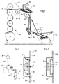
- a paper web 9 is travelling through the final sections of a paper-making machine.
- the web leaves the last roll 10 or cylinder of a preceding section and is guided by paper rolls 11, 12 and 13 to the first roll nip 14 of a calender 15.
- the paper web must be threaded from section to section of the machine and through each of the sections, e.g. through the calender 15.
- a narrow edge strip or lead strip is transferred by means of vacuum belt conveyors 18, 19, 20 along a path 9a (illustrated by a dotted line) into the rope nip at roll 13.
- the ropes 16, 17 transfer the lead strip through the calender.
- the lead strip is widened up to the full width of the web.
- Each of the vacuum conveyors 18, 19, 20 comprises an endless perforated belt travelling over two rolls or pulleys. Between these pulleys, there is a suction box 21 connected to a vacuum source 22. One of the pulleys can be driven by a conventional motor.
- control elements as shown in Figs. 2 and 3 are disposed at an aperture 23 of a side wall 24 of the suction box.
- the external surface of side wall 24 is designated as 25, while the internal surface of side wall 24 is designated as 26.
- a movable element 27 (e.g. in form of a plate) is installed which covers the aperture 23 and is therefore designed to close the same.
- a sealing 28 may be arranged between plate 27 and side wall 24.
- a support 30 (e.g. in form of a bow) is fixed to the internal surface 26 of side wall 24.
- an actuator 31 e.g. in form of an air bag
- the other end of that actuator 31 supports said movable element 27.
- air bag 31 The interior of air bag 31 is connected via line 32, pressure control valve 33 and line 34 to an air pressure supply 35, whereby air bag 31 creates a variable control force or "actuator force A".
- Valve 33 holds said actuator force A at an adjustable set value.
- Valve 33 is (e.g.) self-relieving if the set value is decreased as symbolically illustrated by an arrow 36.
- vacuum source 22 creates in box 21 an internal pressure which is lower than the atmospheric pressure.
- Plate 27 closes the aperture 23 as shown in Fig. 2, if the actuator force A plus a force B (depending from said internal pressure) is greater than a force C (depending from the atmospheric pressure) being effective onto the outer side of plate 27, with the forces A and B acting onto the inner side of plate 27.
- a solenoid valve 37 is energised whereby the interior of actuator 31 is connected to the atmosphere. This action is applied so there is no vacuum acting on the paper web when the ropes have total control of the paper web.
Abstract

Description
- Fig. 1
- shows schematically two sections of a paper-making machine, with some vacuum conveyors being disposed therebetween,
- Fig. 2 and 3
- show details of the vacuum control system of one of the vacuum conveyors of Fig. 1.
Claims (6)
- Vacuum conveyor (20), which is suitable for guiding a running web (9), e.g. paper web, in particular a lead strip (9a) or "threading tail" (e.g. during "threading" of a paper or board web into a machine for the production or finishing or processing of such a web), with the following characteristics:a) an air-pervious endless conveyor belt is tensioned over at least two rolls with a suction box (21) being located in the loop of the conveyor belt and being connected to a source of vacuum (22);b) at least one of the rolls can be driven, to allow the endless conveyor belt to travel over the rolls and over the suction box (21), whereby the vacuum propagates through the run of the conveyor belt running in the direction of web travel, in order to draw the web to be guided onto the conveyor belt by suction;c) a vacuum control (Fig. 2) is adapted to establish a fast decrease of the vacuum degree in the suction box (21);d) the vacuum control comprises a movable element (27) positioned at an inner surface (26) of a wall of the suction box (21) where said wall has an aperture (23) which may be closed by said movable element (27);e) an actuator (31) being connected to the movable element (27) which actuator, in an active state, causes the closing of said aperture (23) by said movable element.
- Vacuum conveyor as claimed in claim 1, characterized by the following features:a) the actuator (31) is an air bag, arranged between a stationary element (30, positioned in the interior of the suction box) and said movable element (27);b) the interior of the air bag (31) is connected to a pressure source (35) via a control line (32, 34) wherein a control valve (33) is arranged to provide in the air bag a constant pressure of adjustable degree.
- Vacuum conveyor as claimed in claim 2, characterized in that the movable element (27) is formed as a plate which is connected to the air bag (31) and which is adapted to contact the inner surface (26) of the suction box (21) in order to close said aperture (23).
- Vacuum conveyor as claimed in claim 2 or 3, characterized in that said control valve (33) is self-relieving.
- Vacuum conveyor as claimed in one of claims 1 to 4, characterized in that the outer side of the movable element (27) is exposed to the atmosphere, while onto its inner side, when the aperture (23) is closed, two forces A and B are effective, wherein force A is created by said actuator (31) and force B depends from the vacuum degree prevailing within the suction box (21).
- Vacuum conveyor as claimed in claim 2, characterized in that an additional valve (37) is arranged in said control line (32) which valve connects the actuator (31) either with the pressure source (35) or with the atmosphere.
Applications Claiming Priority (2)
| Application Number | Priority Date | Filing Date | Title |
|---|---|---|---|
| US371129 | 1999-08-10 | ||
| US09/371,129 US6253983B1 (en) | 1999-08-10 | 1999-08-10 | Vacuum conveyor |
Publications (3)
| Publication Number | Publication Date |
|---|---|
| EP1076131A2 true EP1076131A2 (en) | 2001-02-14 |
| EP1076131A3 EP1076131A3 (en) | 2001-07-18 |
| EP1076131B1 EP1076131B1 (en) | 2004-02-18 |
Family
ID=23462600
Family Applications (1)
| Application Number | Title | Priority Date | Filing Date |
|---|---|---|---|
| EP00115935A Expired - Lifetime EP1076131B1 (en) | 1999-08-10 | 2000-07-25 | Vacuum conveyor |
Country Status (5)
| Country | Link |
|---|---|
| US (1) | US6253983B1 (en) |
| EP (1) | EP1076131B1 (en) |
| AT (1) | ATE259914T1 (en) |
| CA (1) | CA2315501A1 (en) |
| DE (1) | DE60008322T2 (en) |
Cited By (4)
| Publication number | Priority date | Publication date | Assignee | Title |
|---|---|---|---|---|
| GB2388589A (en) * | 2002-05-17 | 2003-11-19 | Hewlett Packard Co | Web feeding in printing and laminating apparatus |
| EP2403790A1 (en) * | 2009-03-02 | 2012-01-11 | Unicharm Corporation | Conveyor apparatus and method of conveying continuous, air-permeable web |
| WO2013092093A1 (en) * | 2011-12-22 | 2013-06-27 | Voith Patent Gmbh | Drying section |
| CN107587371A (en) * | 2016-07-07 | 2018-01-16 | 奥胜制造(太仓)有限公司 | It is used to produce the equipment of the felt in the system of paper web for cleaning |
Families Citing this family (8)
| Publication number | Priority date | Publication date | Assignee | Title |
|---|---|---|---|---|
| US6387220B1 (en) * | 1999-08-13 | 2002-05-14 | Voith Sulzer Papiertechnik Patent Gmbh | Vacuum conveyor |
| DE10105843A1 (en) * | 2001-01-16 | 2002-07-18 | Fleissner Gerold | Method and device for transporting a fleece between two rollers arranged at a distance from one another |
| FI20011372A0 (en) * | 2001-06-27 | 2001-06-27 | Metso Paper Inc | Pulp Machine Threading Arrangement |
| US6841043B2 (en) * | 2002-11-20 | 2005-01-11 | Shawn S. Devoe | Trim hold down box apparatus |
| DE102010064022A1 (en) * | 2010-12-23 | 2012-06-28 | Voith Patent Gmbh | Device for producing and / or treating webs of material |
| CN103832871B (en) * | 2014-02-28 | 2016-04-27 | 河北科技大学 | A kind of waterproof sheet self-threading equipment |
| DE102016209388A1 (en) * | 2016-05-31 | 2017-11-30 | Bhs Corrugated Maschinen- Und Anlagenbau Gmbh | Plant for the production of corrugated board |
| WO2018069404A1 (en) * | 2016-10-14 | 2018-04-19 | Roll-O-Matic A/S | A wrapping device for a machine for winding-up a web material, and a machine for winding-up a web material including the wrapping device |
Citations (2)
| Publication number | Priority date | Publication date | Assignee | Title |
|---|---|---|---|---|
| DE2636887A1 (en) * | 1975-08-18 | 1977-03-10 | Sidney C Rooney | DEVICE FOR THE TRANSFER OF A GUIDE STRIP FOR A PAPER MACHINE O.AE. |
| WO1997016777A1 (en) * | 1995-10-27 | 1997-05-09 | Oce Printing Systems Gmbh | Method of controlling the pressure in a compression chamber |
Family Cites Families (7)
| Publication number | Priority date | Publication date | Assignee | Title |
|---|---|---|---|---|
| US3140030A (en) * | 1962-04-26 | 1964-07-07 | Koppers Co Inc | Vacuum device for pulling a continuous web |
| US3321121A (en) * | 1965-10-22 | 1967-05-23 | Ibm | Feeding apparatus for multi-width tapes |
| US3468606A (en) * | 1968-01-08 | 1969-09-23 | Extek Inc | Method and apparatus for contact printing film |
| US4022366A (en) | 1976-03-22 | 1977-05-10 | Durad Machine Company Ltd. | Sheet handling apparatus |
| US4763822A (en) * | 1985-12-23 | 1988-08-16 | Fibron Machine Corporation | Paper tail nip threader |
| US4821936A (en) * | 1987-09-21 | 1989-04-18 | Mobil Oil Corporation | Hydraulic index drive system |
| DE59702557D1 (en) * | 1996-07-20 | 2000-12-07 | Voith Sulzer Finishing Gmbh | Method for guiding a running paper web or at least one paper web strip cut from it |
-
1999
- 1999-08-10 US US09/371,129 patent/US6253983B1/en not_active Expired - Fee Related
-
2000
- 2000-07-25 AT AT00115935T patent/ATE259914T1/en not_active IP Right Cessation
- 2000-07-25 DE DE60008322T patent/DE60008322T2/en not_active Expired - Fee Related
- 2000-07-25 EP EP00115935A patent/EP1076131B1/en not_active Expired - Lifetime
- 2000-08-09 CA CA002315501A patent/CA2315501A1/en not_active Abandoned
Patent Citations (2)
| Publication number | Priority date | Publication date | Assignee | Title |
|---|---|---|---|---|
| DE2636887A1 (en) * | 1975-08-18 | 1977-03-10 | Sidney C Rooney | DEVICE FOR THE TRANSFER OF A GUIDE STRIP FOR A PAPER MACHINE O.AE. |
| WO1997016777A1 (en) * | 1995-10-27 | 1997-05-09 | Oce Printing Systems Gmbh | Method of controlling the pressure in a compression chamber |
Cited By (10)
| Publication number | Priority date | Publication date | Assignee | Title |
|---|---|---|---|---|
| GB2388589A (en) * | 2002-05-17 | 2003-11-19 | Hewlett Packard Co | Web feeding in printing and laminating apparatus |
| US7005030B2 (en) | 2002-05-17 | 2006-02-28 | Hewlett-Packard Development Company, L.P. | Printing and laminating apparatus |
| GB2388589B (en) * | 2002-05-17 | 2006-09-13 | Hewlett Packard Co | Printing and laminating apparatus |
| EP2403790A1 (en) * | 2009-03-02 | 2012-01-11 | Unicharm Corporation | Conveyor apparatus and method of conveying continuous, air-permeable web |
| EP2403790A4 (en) * | 2009-03-02 | 2013-08-14 | Unicharm Corp | Conveyor apparatus and method of conveying continuous, air-permeable web |
| US9155664B2 (en) | 2009-03-02 | 2015-10-13 | Unicharm Corporation | Conveyor apparatus and method of manufacturing absorbent article |
| WO2013092093A1 (en) * | 2011-12-22 | 2013-06-27 | Voith Patent Gmbh | Drying section |
| CN107587371A (en) * | 2016-07-07 | 2018-01-16 | 奥胜制造(太仓)有限公司 | It is used to produce the equipment of the felt in the system of paper web for cleaning |
| US10780465B2 (en) | 2016-07-07 | 2020-09-22 | Klaus Bartelmuss | Apparatus for cleaning a felt in a system for producing a paper web |
| CN107587371B (en) * | 2016-07-07 | 2020-12-22 | 奥胜制造(太仓)有限公司 | Device for cleaning felt in a system for producing a paper web |
Also Published As
| Publication number | Publication date |
|---|---|
| EP1076131B1 (en) | 2004-02-18 |
| DE60008322D1 (en) | 2004-03-25 |
| EP1076131A3 (en) | 2001-07-18 |
| CA2315501A1 (en) | 2001-02-10 |
| ATE259914T1 (en) | 2004-03-15 |
| US6253983B1 (en) | 2001-07-03 |
| DE60008322T2 (en) | 2005-05-19 |
Similar Documents
| Publication | Publication Date | Title |
|---|---|---|
| EP1076131B1 (en) | Vacuum conveyor | |
| KR0163581B1 (en) | A transfer apparatus for paper web and its method | |
| US4179330A (en) | Apparatus for handling web material, and method | |
| CA1268789A (en) | Apparatus for conveying a web lead-in strip in a paper machine | |
| US5784955A (en) | Calender in a paper-making or a coating machine | |
| CA2229275A1 (en) | A method of and an apparatus for transferring a fast running ready-dried fibrous web, especially a tissue web, from one device and along a predetermined run to a subsequent device | |
| US6972073B2 (en) | Method for conveying and guiding a lead-in strip of a web in a paper machine | |
| EP1076130B1 (en) | Apparatus for transporting a web | |
| US6328852B1 (en) | Method and apparatus for improving stability of moving webs | |
| US6648198B2 (en) | Vacuum belt conveyor | |
| US5238535A (en) | Web pick-up device and method for transfer of a paper web | |
| US6387220B1 (en) | Vacuum conveyor | |
| CA1282762C (en) | Web reeling method and apparatus | |
| JP3518867B2 (en) | Assembly for paper web coating line | |
| US3419203A (en) | High speed paper making machine | |
| JP2003064592A (en) | Apparatus for treating fibrous web | |
| CA2398917A1 (en) | Apparatus for treating a fibrous web | |
| JPH073688A (en) | Fibrous web transferring device | |
| CA2206838A1 (en) | Method and device in threading of a paper web | |
| US5720852A (en) | Method and device for stabilizing the running of a paper web in connection with a paper guide roll | |
| US6145218A (en) | Drying section and method for drying a material web in such a drying section | |
| US3813019A (en) | Web stabilizing device | |
| JPH11508000A (en) | Apparatus and method for stabilizing a paper web in the region of a roll in a paper machine | |
| US5832626A (en) | Single felt dryer group | |
| CA2427591C (en) | Device for conveying and guiding a lead-in strip of a web in a paper machine |
Legal Events
| Date | Code | Title | Description |
|---|---|---|---|
| PUAI | Public reference made under article 153(3) epc to a published international application that has entered the european phase |
Free format text: ORIGINAL CODE: 0009012 |
|
| AK | Designated contracting states |
Kind code of ref document: A2 Designated state(s): AT DE FI GB SE |
|
| AX | Request for extension of the european patent |
Free format text: AL;LT;LV;MK;RO;SI |
|
| PUAL | Search report despatched |
Free format text: ORIGINAL CODE: 0009013 |
|
| AK | Designated contracting states |
Kind code of ref document: A3 Designated state(s): AT BE CH CY DE DK ES FI FR GB GR IE IT LI LU MC NL PT SE |
|
| AX | Request for extension of the european patent |
Free format text: AL;LT;LV;MK;RO;SI |
|
| 17P | Request for examination filed |
Effective date: 20010810 |
|
| AKX | Designation fees paid |
Free format text: AT DE FI GB SE |
|
| GRAP | Despatch of communication of intention to grant a patent |
Free format text: ORIGINAL CODE: EPIDOSNIGR1 |
|
| GRAS | Grant fee paid |
Free format text: ORIGINAL CODE: EPIDOSNIGR3 |
|
| GRAA | (expected) grant |
Free format text: ORIGINAL CODE: 0009210 |
|
| AK | Designated contracting states |
Kind code of ref document: B1 Designated state(s): AT DE FI GB SE |
|
| REG | Reference to a national code |
Ref country code: GB Ref legal event code: FG4D |
|
| REF | Corresponds to: |
Ref document number: 60008322 Country of ref document: DE Date of ref document: 20040325 Kind code of ref document: P |
|
| REG | Reference to a national code |
Ref country code: SE Ref legal event code: TRGR |
|
| PLBE | No opposition filed within time limit |
Free format text: ORIGINAL CODE: 0009261 |
|
| STAA | Information on the status of an ep patent application or granted ep patent |
Free format text: STATUS: NO OPPOSITION FILED WITHIN TIME LIMIT |
|
| 26N | No opposition filed |
Effective date: 20041119 |
|
| PGFP | Annual fee paid to national office [announced via postgrant information from national office to epo] |
Ref country code: AT Payment date: 20050628 Year of fee payment: 6 |
|
| PGFP | Annual fee paid to national office [announced via postgrant information from national office to epo] |
Ref country code: DE Payment date: 20050714 Year of fee payment: 6 Ref country code: SE Payment date: 20050714 Year of fee payment: 6 |
|
| PGFP | Annual fee paid to national office [announced via postgrant information from national office to epo] |
Ref country code: FI Payment date: 20050715 Year of fee payment: 6 |
|
| PGFP | Annual fee paid to national office [announced via postgrant information from national office to epo] |
Ref country code: GB Payment date: 20050725 Year of fee payment: 6 |
|
| PG25 | Lapsed in a contracting state [announced via postgrant information from national office to epo] |
Ref country code: AT Free format text: LAPSE BECAUSE OF NON-PAYMENT OF DUE FEES Effective date: 20060725 Ref country code: GB Free format text: LAPSE BECAUSE OF NON-PAYMENT OF DUE FEES Effective date: 20060725 Ref country code: FI Free format text: LAPSE BECAUSE OF NON-PAYMENT OF DUE FEES Effective date: 20060725 |
|
| PG25 | Lapsed in a contracting state [announced via postgrant information from national office to epo] |
Ref country code: SE Free format text: LAPSE BECAUSE OF NON-PAYMENT OF DUE FEES Effective date: 20060726 |
|
| PG25 | Lapsed in a contracting state [announced via postgrant information from national office to epo] |
Ref country code: DE Free format text: LAPSE BECAUSE OF NON-PAYMENT OF DUE FEES Effective date: 20070201 |
|
| EUG | Se: european patent has lapsed | ||
| GBPC | Gb: european patent ceased through non-payment of renewal fee |
Effective date: 20060725 |