EP1075062A2 - Article comprising a fiber raman device - Google Patents
Article comprising a fiber raman device Download PDFInfo
- Publication number
- EP1075062A2 EP1075062A2 EP00306288A EP00306288A EP1075062A2 EP 1075062 A2 EP1075062 A2 EP 1075062A2 EP 00306288 A EP00306288 A EP 00306288A EP 00306288 A EP00306288 A EP 00306288A EP 1075062 A2 EP1075062 A2 EP 1075062A2
- Authority
- EP
- European Patent Office
- Prior art keywords
- fiber
- raman
- wavelength
- radiation
- pump
- Prior art date
- Legal status (The legal status is an assumption and is not a legal conclusion. Google has not performed a legal analysis and makes no representation as to the accuracy of the status listed.)
- Granted
Links
Images


Classifications
-
- H—ELECTRICITY
- H01—ELECTRIC ELEMENTS
- H01S—DEVICES USING THE PROCESS OF LIGHT AMPLIFICATION BY STIMULATED EMISSION OF RADIATION [LASER] TO AMPLIFY OR GENERATE LIGHT; DEVICES USING STIMULATED EMISSION OF ELECTROMAGNETIC RADIATION IN WAVE RANGES OTHER THAN OPTICAL
- H01S3/00—Lasers, i.e. devices using stimulated emission of electromagnetic radiation in the infrared, visible or ultraviolet wave range
- H01S3/30—Lasers, i.e. devices using stimulated emission of electromagnetic radiation in the infrared, visible or ultraviolet wave range using scattering effects, e.g. stimulated Brillouin or Raman effects
- H01S3/302—Lasers, i.e. devices using stimulated emission of electromagnetic radiation in the infrared, visible or ultraviolet wave range using scattering effects, e.g. stimulated Brillouin or Raman effects in an optical fibre
-
- H—ELECTRICITY
- H01—ELECTRIC ELEMENTS
- H01S—DEVICES USING THE PROCESS OF LIGHT AMPLIFICATION BY STIMULATED EMISSION OF RADIATION [LASER] TO AMPLIFY OR GENERATE LIGHT; DEVICES USING STIMULATED EMISSION OF ELECTROMAGNETIC RADIATION IN WAVE RANGES OTHER THAN OPTICAL
- H01S3/00—Lasers, i.e. devices using stimulated emission of electromagnetic radiation in the infrared, visible or ultraviolet wave range
- H01S3/05—Construction or shape of optical resonators; Accommodation of active medium therein; Shape of active medium
- H01S3/06—Construction or shape of active medium
- H01S3/063—Waveguide lasers, i.e. whereby the dimensions of the waveguide are of the order of the light wavelength
- H01S3/067—Fibre lasers
- H01S3/06754—Fibre amplifiers
-
- H—ELECTRICITY
- H01—ELECTRIC ELEMENTS
- H01S—DEVICES USING THE PROCESS OF LIGHT AMPLIFICATION BY STIMULATED EMISSION OF RADIATION [LASER] TO AMPLIFY OR GENERATE LIGHT; DEVICES USING STIMULATED EMISSION OF ELECTROMAGNETIC RADIATION IN WAVE RANGES OTHER THAN OPTICAL
- H01S3/00—Lasers, i.e. devices using stimulated emission of electromagnetic radiation in the infrared, visible or ultraviolet wave range
- H01S3/09—Processes or apparatus for excitation, e.g. pumping
- H01S3/091—Processes or apparatus for excitation, e.g. pumping using optical pumping
- H01S3/094—Processes or apparatus for excitation, e.g. pumping using optical pumping by coherent light
- H01S3/094003—Processes or apparatus for excitation, e.g. pumping using optical pumping by coherent light the pumped medium being a fibre
-
- H—ELECTRICITY
- H01—ELECTRIC ELEMENTS
- H01S—DEVICES USING THE PROCESS OF LIGHT AMPLIFICATION BY STIMULATED EMISSION OF RADIATION [LASER] TO AMPLIFY OR GENERATE LIGHT; DEVICES USING STIMULATED EMISSION OF ELECTROMAGNETIC RADIATION IN WAVE RANGES OTHER THAN OPTICAL
- H01S3/00—Lasers, i.e. devices using stimulated emission of electromagnetic radiation in the infrared, visible or ultraviolet wave range
- H01S3/09—Processes or apparatus for excitation, e.g. pumping
- H01S3/091—Processes or apparatus for excitation, e.g. pumping using optical pumping
- H01S3/094—Processes or apparatus for excitation, e.g. pumping using optical pumping by coherent light
- H01S3/094003—Processes or apparatus for excitation, e.g. pumping using optical pumping by coherent light the pumped medium being a fibre
- H01S3/094011—Processes or apparatus for excitation, e.g. pumping using optical pumping by coherent light the pumped medium being a fibre with bidirectional pumping, i.e. with injection of the pump light from both two ends of the fibre
-
- H—ELECTRICITY
- H01—ELECTRIC ELEMENTS
- H01S—DEVICES USING THE PROCESS OF LIGHT AMPLIFICATION BY STIMULATED EMISSION OF RADIATION [LASER] TO AMPLIFY OR GENERATE LIGHT; DEVICES USING STIMULATED EMISSION OF ELECTROMAGNETIC RADIATION IN WAVE RANGES OTHER THAN OPTICAL
- H01S3/00—Lasers, i.e. devices using stimulated emission of electromagnetic radiation in the infrared, visible or ultraviolet wave range
- H01S3/09—Processes or apparatus for excitation, e.g. pumping
- H01S3/091—Processes or apparatus for excitation, e.g. pumping using optical pumping
- H01S3/094—Processes or apparatus for excitation, e.g. pumping using optical pumping by coherent light
- H01S3/094042—Processes or apparatus for excitation, e.g. pumping using optical pumping by coherent light of a fibre laser
-
- H—ELECTRICITY
- H01—ELECTRIC ELEMENTS
- H01S—DEVICES USING THE PROCESS OF LIGHT AMPLIFICATION BY STIMULATED EMISSION OF RADIATION [LASER] TO AMPLIFY OR GENERATE LIGHT; DEVICES USING STIMULATED EMISSION OF ELECTROMAGNETIC RADIATION IN WAVE RANGES OTHER THAN OPTICAL
- H01S3/00—Lasers, i.e. devices using stimulated emission of electromagnetic radiation in the infrared, visible or ultraviolet wave range
- H01S3/09—Processes or apparatus for excitation, e.g. pumping
- H01S3/091—Processes or apparatus for excitation, e.g. pumping using optical pumping
- H01S3/094—Processes or apparatus for excitation, e.g. pumping using optical pumping by coherent light
- H01S3/094042—Processes or apparatus for excitation, e.g. pumping using optical pumping by coherent light of a fibre laser
- H01S3/094046—Processes or apparatus for excitation, e.g. pumping using optical pumping by coherent light of a fibre laser of a Raman fibre laser
-
- H—ELECTRICITY
- H01—ELECTRIC ELEMENTS
- H01S—DEVICES USING THE PROCESS OF LIGHT AMPLIFICATION BY STIMULATED EMISSION OF RADIATION [LASER] TO AMPLIFY OR GENERATE LIGHT; DEVICES USING STIMULATED EMISSION OF ELECTROMAGNETIC RADIATION IN WAVE RANGES OTHER THAN OPTICAL
- H01S3/00—Lasers, i.e. devices using stimulated emission of electromagnetic radiation in the infrared, visible or ultraviolet wave range
- H01S3/09—Processes or apparatus for excitation, e.g. pumping
- H01S3/091—Processes or apparatus for excitation, e.g. pumping using optical pumping
- H01S3/094—Processes or apparatus for excitation, e.g. pumping using optical pumping by coherent light
- H01S3/094096—Multi-wavelength pumping
-
- H—ELECTRICITY
- H01—ELECTRIC ELEMENTS
- H01S—DEVICES USING THE PROCESS OF LIGHT AMPLIFICATION BY STIMULATED EMISSION OF RADIATION [LASER] TO AMPLIFY OR GENERATE LIGHT; DEVICES USING STIMULATED EMISSION OF ELECTROMAGNETIC RADIATION IN WAVE RANGES OTHER THAN OPTICAL
- H01S3/00—Lasers, i.e. devices using stimulated emission of electromagnetic radiation in the infrared, visible or ultraviolet wave range
- H01S3/30—Lasers, i.e. devices using stimulated emission of electromagnetic radiation in the infrared, visible or ultraviolet wave range using scattering effects, e.g. stimulated Brillouin or Raman effects
Definitions
- This invention pertains to articles (e.g., an optical fiber communication system, or a light source or amplifier for such a system) that comprise an optical fiber Raman device.
- Fiber Raman devices Optical fiber Raman lasers and amplifiers (collectively “fiber Raman devices”) are known. See, for instance, U.S. Patent 5,323,404 for exemplary embodiments of fiber Raman devices of a first (topologically. linear) type, with fiber gratings acting as wavelength-selective elements.
- An optical fiber Raman device can be used to provide pump light (exemplarily of wavelength 1480 nm) to an Er-doped fiber amplifier (EDFA), or can be used to amplify signal light (e.g., at 1310nm).
- EDFA Er-doped fiber amplifier
- Fig. 1 schematically depicts a prior art fiber Ranian laser 10 of the topologically linear type, suitable for pumping of an EDFA.
- Cladding pumped fiber laser (CPFL) 11 provides pump light of a predetermined wavelength (e.g., 1117 nm) to the Raman laser.
- Raman fiber 12 typically is a silica-based fiber with Ge-doped core, and typically is hundreds of meters long.
- Numerals 13 and 14 refer to the upstream and downstream grating sets, respectively. It will be appreciated that in a schematically depicted grating set herein each cross-line indicates a separate grating.
- the upstream set 13 typically comprises only high reflectivity (HR) gratings (exemplarily of center wavelengths 1175, 1240, 1315, 1395, and 1480nm), and the downstream set 14 typically comprises, in addition to the HR gratings, also a grating of relatively low reflectivity, to provide output coupling.
- HR high reflectivity
- the downstream gratings have center wavelengths 1117, 1175, 1240, 1315, 1395 and 1480nm, with the 1117nm grating serving as pump reflector.
- the output coupler has center wavelength corresponding to the desired output wavelength, exemplarily 1480 nm.
- CPFLs are known, and are commercially available. See for instance, U.S. patent applications Serial numbers 08/897,195 and 08/999,429, respectively filed July 21, 1997 and December 29, 1997 by DiGiovanni et al.
- a CPFL comprises several high power light emitting diodes (exemplarily InGaAlAs diodes).
- the output of each LED is coupled into a multimode fiber, e.g., a silica-based fiber with 0.22 N.A., 105 ⁇ m core and 125 ⁇ m outside diameter.
- the fibers are arranged into a bundle, fused together and tapered, as described, for instance, in US patent application Serial No. 09/315,631, filed May 20, 1999 by D.J. DiGiovanni et al.
- This application discloses an article that comprises a fiber Raman device that is pumped with light from more than seven pump LEDs, exemplarily 14 pump LEDs.
- light and radiation are used herein interchangeably for electromagnetic radiation of interest herein, typically infrared radiation.
- Optical fiber gratings and fused fiber couplers are herein collectively referred to as "wavelength-selective elements".
- a fused fiber coupler is frequently referred to as a "WDM”.
- the "Raman spectrum" of an optical fiber is the scattered intensity as a function of wavelength difference from an incident radiation.
- a shift to longer wavelength is generally referred to as a Stokes shift.
- the Stokes shift is expressed in inverse centimeters (cm -1 ), but it can also be expressed in terms of wavelengths.
- the Raman spectrum of germano-silicate glass is relatively broad, with a pronounced maximum at a Stokes shift of about 440cm -1 , relative to the wavelength of the pump light. See Fig. 2 herein, which shows the Raman spectrum for pump tight of 1427nm.
- a wavelength-selective element in a Raman device that is responsive to a given pump light is herein referred to as being “on resonance” (with respect to the pump light), and an element that is not responsive to the given pump light is herein referred to as being “off resonance” (with respect to the pump light).
- a wavelength-selective element is "responsive" to a given pump light if the element/light interaction is at or near maximum, for instance, if the pump light is within the wavelength range wherein the reflectivity of the grating is 50% or more of the maximum reflectivity of the grating, or wherein the coupling strength of a fiber coupler (WDM) is 50% or more of the maximum coupling strength of the coupler.
- WDM fiber coupler
- the invention is embodied in an optical fiber communication system or other article that comprises an optical fiber Raman device that is adapted for utilizing high pump power.
- the Raman device comprises a length of silica-based optical fiber comprising at least a first and a second wavelength-selective element disposed to provide one or more optical cavities for Raman-shifting of light in said optical fiber, and further comprises a first coupler for coupling pump radiation of a first wavelength ⁇ 1 from a first pump radiation source into said optical fiber, and still further comprises means for providing a Raman-shifted Raman device output radiation of wavelength ⁇ 0 greater than ⁇ 1 to output radiation utilization means.
- the fiber Raman device further comprises a second coupler for coupling pump radiation of a second wavelength ⁇ 2 from a second pump radiation source into said optical fiber, where ⁇ 2 is different from ⁇ 1 , with ⁇ 0 > ⁇ 2 , wherein at least one of said wavelength-selective elements is off resonance with regard to at least one of ⁇ 1 and ⁇ 2 .
- the fiber Raman device is a topologically linear Raman laser then the first and second wavelength selective elements typically are fiber gratings, and the means for providing the output radiation to utilization means exemplarily comprise an output coupler of relatively low reflectivity. If the device is a topologically circular Raman laser then the wavelength selective elements typically are fiber couplers (WDMs), and the means for providing the output radiation typically also comprise a WDM.
- WDMs fiber couplers
- the wavelength selective elements typically are fiber gratings, and the means for providing the output radiation to utilization means comprise a high-reflectivity optical cavity for radiation that is one Stokes shift from a signal radiation. If the device is a topologically circular Raman amplifier then the wavelength selective elements typically are WDMs, and the means for providing the output radiation typically also comprise a WDM.
- Raman device is a topologically linear Raman device then
- the invention is not limited to any particular set of pump wavelengths and/or sets of fiber gratings or other wavelength-selective elements, and all fiber Raman devices with suitable pump wavelengths (at least one off resonance) and wavelength-selective elements are contemplated.
- Fig. 2 shows the Raman spectrum of a conventional silica-based fiber with germanosilicate core, pumped with 1427nm pump light.
- the maximum scattered intensity occurs at about 1521nm, but significant intensity extends over the approximate range 1460-1550nm.
- the wavelength-selective elements in a fiber Raman laser need not be selected to yield the exact maximum Raman scattering but can depart somewhat from that value, with relatively insignificant decrease in scattering intensity. It will be understood that the spectrum of Fig. 2 is specific to the pump wavelength used.
- prior art fiber Raman lasers In (topologically linear) prior art fiber Raman lasers it is conventional to provide a pump reflector fiber grating that has substantially 100% reflectivity at the wavelength of the pump source 11.
- prior art fiber Raman lasers also comprise wavelength-selective elements that form one or more optical cavities. Each cavity comprises two spaced apart fiber gratings that have high reflectivity at essentially the same wavelength. This is schematically depicted in Fig. 1 for an exemplary prior art Raman laser having 1117 nm pump radiation and 1480 nm output radiation. Each cross line of sets 13 and 14 indicates a fiber (Bragg) grating.
- the gratings of grating set 13 have minimum transmission at 1480, 1395, 1315, 1240 and 1175nm, respectively.
- the gratings of set 14 have minimum transmission of 1117, 1175, 1240, 1315, 1385 and 1480, respectively, with the 1480nm grating serving as output coupler.
- the order in which the gratings are arranged is generally not critical.
- Pump radiation of wavelength 1117 nm is coupled into the Raman fiber and travels in the downstream direction to the 1117 nm pump reflector grating, where essentially all of the remaining 1117nm radiation is reflected.
- the 1117 nm radiation undergoes Raman scattering, which results in a build-up of 1175 nm radiation in the 1175 nm optical cavity.
- Raman scattering of the 1175 nm radiation results in build-up of 1240 nm radiation in the 1240 nm optical cavity, and so on, until 1480 nm radiation is coupled out of the Raman laser.
- Grating 15 (1480 nm) serves as output coupler, facilitating emission of 1480 nm output radiation from the 1480 nm optical cavity.
- grating 15 has reflectivity in the range 4-15% at 1480 nm.
- fiber Bragg gratings have bilateral symmetry. That is to say, the device has the same response spectrum for light traveling in one direction in the fiber as for light traveling in the opposite direction.
- pump reflector 16 has high reflectivity for 1117 nm radiation propagating downstream then the pump reflector also has high reflectivity for 1117 nm radiation that propagates upstream, and pumping of the structure with 1117nm radiation from both sides would not be effective.
- fiber Bragg gratings can be fabricated to have high reflectivity at a first wavelength (e.g., 1117 nm) and to have low reflectivity (e.g., transmission more than about 98%) at a nearby second wavelength (e.g., 1115 nm).
- Fig. 4 shows the spectrum of an exemplary fiber Bragg grating that can be used to practice the invention.
- Fig. 4 also shows that the grating has high transmission (and therefore has low reflection) in a spectral region on the low wavelength side of the reflectivity peak.
- FIG. 3 schematically shows an exemplary laser according to the invention.
- the laser of FIG. 3 resembles the prior art laser of FIG. 1 but exhibits significant differences.
- the laser of FIG. 3 comprises an additional CPFL 111, the output of the CPFL being coupled into the Raman fiber 12 by means of WDM 21.
- the output of CPFL11 (wavelength 1117nm) is on resonance with the pump reflector (1117nm)
- the output of CPFL 111 (wavelength 1115nm) is off resonance with respect to that reflector.
- the off resonance pump radiation is coupled into the Raman fiber 12, and propagates in the upstream direction substantially without interaction with gratings 141 and 13. Propagation of the 1115nm pump radiation through Raman fiber 12 to the set of gratings 13 results in Stokes shifting of the 1115nm pump radiation, with the Stokes shifted radiation propagating in the downstream direction.
- the Raman spectrum of silica being relatively broad (see FIG. 2), the 1175nm light generated by the 1175nm cavity is almost as effective for stimulating the Stokes shift of the 1115nm pump radiation as it is for the Stokes shift of the 1117nm pump radiation. This is considered to be a significant feature of apparatus according to the invention.
- the set of gratings 13 of FIG. 3 optionally comprises a pump reflector grating (not shown) with center wavelength 1115nm, that reflects the unshifted 1115nm pump radiation.
- FIG. 5 corresponds to FIG. 1 of the reference.
- Yb-doped fiber laser 51 provides 1.06 ⁇ m input to the Raman laser.
- the ring cavity of the Raman laser comprises a WDM coupler 53 having ports 1-4, Ge-doped single mode silica fiber (1.2km) 52, high reflector 55, and input/output WDM coupler 54.
- the pump radiation is coupled into the Raman laser through WDM coupler 54 with center wavelengths at 1.06 and 1.24 ⁇ m. Since the Raman frequency shift in the fiber is about 440cm -1 , conversion from 1.06 to 1.24 ⁇ m occurs through cascaded Raman scattering up to third order via two intermediate Stokes orders centered at 1.12 and 1.18 ⁇ m.
- the laser cavity therefore allows coupling of the pump power into the active Raman fiber and resonates in the first and second Stokes orders, leading to high intercavity intensities and minimized losses.
- the fused tapered coupler 53 is designed to transmit about 80% of the pump inside the loop at 1.06 ⁇ m from port 1 to 3.
- a fiber-bend-type filter (not shown) is formed inside the cavity.
- the Raman laser output is finally coupled out of the cavity through WDM 54.
- FIG. 6 schematically depicts an exemplary Raman laser according to the invention that resembles the above described (topologically circular) prior art laser of FIG. 5.
- the laser according to the invention comprises a further pump source 66 having an output of wavelength different from that of source 51 (e.g., 1050nm), and fused fiber coupler 67 is selected to facilitate coupling of the 1050nm (off-resonance with respect to coupler 53, so that 85-95% couplers from port 3 to port 4) pump radiation into Raman fiber 52.
- fused fiber couplers are the wavelength selective elements.
- a (topologically linear) Raman amplifier resembles a (topologically linear) Raman laser, with pump radiation being Raman shifted through one or more stages, such that the resulting pump radiation has a wavelength that is one Stokes shift below a predetermined signal radiation.
- the pump radiation is coupled into a silica-based optical fiber that carries the signal light, the signal radiation stimulating the energy transfer from the pump radiation to the signal radiation.
- a (topologically circular) Raman amplifier according to the invention is structured substantially as shown in Fig. 6, with the output radiation during operation of the amplifier coupled into an optical fiber that carries the signal radiation.
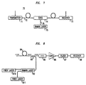
- FIG. 7 schematically shows an exemplary optical fiber communication system 70 according to the invention, wherein numerals 71-76 respectively refer to a transmitter, optical transmission fiber, receiver, EDFA, Raman laser according to this invention, and Raman laser output radiation, e.g., 1480nm radiation
- FIG. 8 schematically depicts an exemplary Raman amplifier with associated components.
- Fiber laser 810 typically a Yb +3 cladding pumped fiber laser, provides 1117nm pump light to Raman laser 82, and fiber laser 811 provides 1115 pump light.
- the Raman laser is selected to have output light of wavelength 1453nm.
- the 1453nm pump light is coupled into the signal transmission path by conventional WDM 83 and propagates upstream through a length (e.g., about 20 km) of germanosilicate fiber, through which one or more signals (wavelengths about 1.55 ⁇ m) propagate in the downstream direction.
- the signals are being amplified in conventional manner by stimulated Raman scattering.
- the amplified signal(s) propagates through a conventional optical isolator 85, a conventional EDFA 86, and a conventional band pass filter 87 to conventional receiver 88.
Landscapes
- Physics & Mathematics (AREA)
- Electromagnetism (AREA)
- Engineering & Computer Science (AREA)
- Plasma & Fusion (AREA)
- Optics & Photonics (AREA)
- Lasers (AREA)
- Optical Modulation, Optical Deflection, Nonlinear Optics, Optical Demodulation, Optical Logic Elements (AREA)
Abstract
Description
Claims (8)
- An article comprising a fiber Raman device comprising:a) a length of silica-based optical fiber comprising at least a first and second wavelength-selective element disposed to provide one or more optical cavities for Raman-shifting of light in said optical fiber,b) a first coupler for coupling pump radiation of a first wavelength λ1 from a first pump radiation source into said optical fiber, andc) means for providing a Raman device output radiation of wavelength λ0 to output radiation utilization means, where λ0>λ1;
CHARACTERIZED IN THAT the Raman device further comprisesd) a second coupler for coupling pump radiation of a second wavelength λ2 from a second pump radiation source into said optical fiber, where λ2 is different from λ1, with λ0>λ2, and wherein at least one of said wavelength-selective elements is off resonance with regard to at least one of λ1 and λ2. - Article according to claim 1, wherein said fiber Raman device is a fiber Raman laser.
- Article according to claim 1, wherein said fiber Raman device is a fiber Raman amplifier.
- Article according to claim 1, wherein said one or more wavelength-selective elements are selected such that one of said wavelength-selective elements is on resonance.
- Article according to claim 1, wherein said one or more wavelength-selective elements are selected such that both of said wavelength-selective elements are off resonance.
- Article according to claim 1, wherein said fiber Raman device is a topologically linear fiber Raman device, wherein |λ1-λ2| is greater than 0.2nm, or wherein said fiber Raman device is a topologically circular fiber Raman device, wherein |λ1-λ2| is greater than 3nm.
- Article according to claim 1, wherein said fiber Raman device is a topologically linear fiber Raman laser or a topologically linear fiber Raman amplifier, and said wavelength-selective elements comprise optical fiber Bragg gratings.
- Article according to claim 1, wherein said fiber Raman device is a topologically circular fiber Raman amplifier or a topologically circular fiber Raman laser, and said wavelength-selective elements comprise fiber couplers.
Applications Claiming Priority (2)
| Application Number | Priority Date | Filing Date | Title |
|---|---|---|---|
| US09/369,393 US6434172B1 (en) | 1999-08-06 | 1999-08-06 | Article comprising a fiber raman device |
| US369393 | 1999-08-06 |
Publications (3)
| Publication Number | Publication Date |
|---|---|
| EP1075062A2 true EP1075062A2 (en) | 2001-02-07 |
| EP1075062A3 EP1075062A3 (en) | 2002-06-12 |
| EP1075062B1 EP1075062B1 (en) | 2005-11-16 |
Family
ID=23455300
Family Applications (1)
| Application Number | Title | Priority Date | Filing Date |
|---|---|---|---|
| EP00306288A Expired - Lifetime EP1075062B1 (en) | 1999-08-06 | 2000-07-24 | Article comprising a fiber raman device |
Country Status (4)
| Country | Link |
|---|---|
| US (1) | US6434172B1 (en) |
| EP (1) | EP1075062B1 (en) |
| JP (2) | JP4149641B2 (en) |
| DE (1) | DE60024002T2 (en) |
Cited By (1)
| Publication number | Priority date | Publication date | Assignee | Title |
|---|---|---|---|---|
| WO2004054050A1 (en) * | 2002-12-10 | 2004-06-24 | Nikon Corporation | Ultraviolet light source, phototherapy apparatus using ultraviolet light source, and exposure system using ultraviolet light source |
Families Citing this family (29)
| Publication number | Priority date | Publication date | Assignee | Title |
|---|---|---|---|---|
| GB9928474D0 (en) * | 1999-12-03 | 2000-02-02 | Secr Defence Brit | Laser effects and laser devices |
| RU2158458C1 (en) * | 2000-02-08 | 2000-10-27 | Научный центр волоконной оптики при Институте общей физики РАН | Raman fiber laser |
| DE60134902D1 (en) * | 2000-02-29 | 2008-09-04 | Nec Corp | Method and apparatus for laser amplification |
| JP2002006348A (en) * | 2000-06-21 | 2002-01-09 | Mitsubishi Electric Corp | Optical amplifier |
| US6624927B1 (en) * | 2001-03-14 | 2003-09-23 | Onetta, Inc. | Raman optical amplifiers |
| US6845194B2 (en) * | 2001-06-27 | 2005-01-18 | Furukawa Electric North America Inc. | Optical bandpass filter using long period gratings |
| US20030021302A1 (en) * | 2001-07-18 | 2003-01-30 | Grudinin Anatoly Borisovich | Raman cascade light sources |
| US6839377B2 (en) * | 2001-10-26 | 2005-01-04 | Agere Systems, Inc. | Optoelectronic device having a fiber grating stabilized pump module with increased locking range and a method of manufacture therefor |
| US6646785B2 (en) * | 2002-01-31 | 2003-11-11 | Corning Incorporated | Fiber ring amplifiers and lasers |
| EP1349242A1 (en) * | 2002-03-27 | 2003-10-01 | Alcatel | Raman fiber amplification stage; optical system and method to control the raman amplification stage |
| KR100628472B1 (en) * | 2004-05-24 | 2006-09-26 | 한국과학기술연구원 | Raman or Erbium fiber lasers using fiber optic gratings and long-range sensors for simultaneous temperature and strain measurements |
| US7391561B2 (en) | 2005-07-29 | 2008-06-24 | Aculight Corporation | Fiber- or rod-based optical source featuring a large-core, rare-earth-doped photonic-crystal device for generation of high-power pulsed radiation and method |
| ITMI20051625A1 (en) * | 2005-09-01 | 2007-03-02 | Marconi Comm Spa | OPTICAL AMPLIFIER AND WDM RING NETWORK ALL OPTICAL IN METROPOLITAN CONTEXT WITH IT |
| US7768700B1 (en) | 2006-11-30 | 2010-08-03 | Lockheed Martin Corporation | Method and apparatus for optical gain fiber having segments of differing core sizes |
| US8179594B1 (en) | 2007-06-29 | 2012-05-15 | Lockheed Martin Corporation | Method and apparatus for spectral-beam combining of fanned-in laser beams with chromatic-dispersion compensation using a plurality of diffractive gratings |
| JP4873645B2 (en) * | 2007-08-15 | 2012-02-08 | 新日本製鐵株式会社 | Optical fiber Raman laser device |
| JP5323562B2 (en) * | 2008-03-31 | 2013-10-23 | 古河電気工業株式会社 | Cascade Raman laser |
| US8503840B2 (en) | 2010-08-23 | 2013-08-06 | Lockheed Martin Corporation | Optical-fiber array method and apparatus |
| US8441718B2 (en) * | 2009-11-23 | 2013-05-14 | Lockheed Martin Corporation | Spectrally beam combined laser system and method at eye-safer wavelengths |
| DE102009056058B4 (en) * | 2009-11-25 | 2021-08-12 | Fraunhofer-Gesellschaft zur Förderung der angewandten Forschung e.V. | Device for generating excitation radiation for self-calibrating fiber optic Raman sensors, measuring device for detecting the temperature of a measurement object and Raman sensor arrangement |
| US20110134940A1 (en) * | 2009-12-08 | 2011-06-09 | Schlumberger Technology Corporation | Narrow linewidth brillouin laser |
| DE112011101288T5 (en) | 2010-04-12 | 2013-02-07 | Lockheed Martin Corporation | Beam diagnostic and feedback system and methods for spectrally beam combined lasers |
| IL221918A (en) * | 2012-09-12 | 2016-11-30 | V-Gen Ltd | Optical isolator |
| US9366872B2 (en) | 2014-02-18 | 2016-06-14 | Lockheed Martin Corporation | Apparatus and method for fiber-laser output-beam shaping for spectral beam combination |
| US9575390B2 (en) * | 2015-03-31 | 2017-02-21 | Ipg Photonics Corporation | Higher order seedless raman pumping |
| FR3050289B1 (en) * | 2016-04-13 | 2018-04-06 | Centre National De La Recherche Scientifique - Cnrs - | DEVICE FOR GENERATING A WAVE LENGTH PHOTON BEAM DEFINING A SUBSTANTIALLY CONTINUOUS SUPERCONTINUUM |
| EP3611494A1 (en) * | 2018-08-17 | 2020-02-19 | Koninklijke Philips N.V. | System and method for providing an indication of a person's gum health |
| JP6785901B2 (en) * | 2019-02-21 | 2020-11-18 | 株式会社フジクラ | Filter device, laser device |
| CN112414760B (en) * | 2020-11-24 | 2022-06-21 | 桂林电子科技大学 | Ring fiber core beak-shaped optical fiber tweezers system with stable capturing function |
Family Cites Families (13)
| Publication number | Priority date | Publication date | Assignee | Title |
|---|---|---|---|---|
| US4741587A (en) * | 1986-02-20 | 1988-05-03 | American Telephone And Telegraph Company, At&T Bell Laboratories | Optical communications system and method for the generation of a sequence of optical pulses by means of induced modulational instability |
| US5323404A (en) * | 1993-11-02 | 1994-06-21 | At&T Bell Laboratories | Optical fiber laser or amplifier including high reflectivity gratings |
| US5673280A (en) | 1996-02-12 | 1997-09-30 | Lucent Technologies Inc. | Article comprising low noise optical fiber raman amplifier |
| US5623508A (en) * | 1996-02-12 | 1997-04-22 | Lucent Technologies Inc. | Article comprising a counter-pumped optical fiber raman amplifier |
| US5659644A (en) * | 1996-06-07 | 1997-08-19 | Lucent Technologies Inc. | Fiber light source with multimode fiber coupler |
| JPH1073852A (en) * | 1996-09-02 | 1998-03-17 | Nippon Telegr & Teleph Corp <Ntt> | Optical amplification transmission system |
| US5923684A (en) * | 1996-09-26 | 1999-07-13 | Lucent Technologies Inc. | Fiber amplifier with multiple pass pumping |
| US6212310B1 (en) * | 1996-10-22 | 2001-04-03 | Sdl, Inc. | High power fiber gain media system achieved through power scaling via multiplexing |
| US5815518A (en) * | 1997-06-06 | 1998-09-29 | Lucent Technologies Inc. | Article comprising a cascaded raman fiber laser |
| US5966480A (en) * | 1998-02-23 | 1999-10-12 | Lucent Technologies Inc. | Article comprising an improved cascaded optical fiber Raman device |
| US6310899B1 (en) * | 1998-04-15 | 2001-10-30 | Lucent Technologies Inc. | Cascaded raman resonator system and apparatus |
| US6163552A (en) * | 1998-08-14 | 2000-12-19 | Lucent Technologies Inc. | Article comprising an optical fiber cascaded Raman resonator |
| RU2158458C1 (en) * | 2000-02-08 | 2000-10-27 | Научный центр волоконной оптики при Институте общей физики РАН | Raman fiber laser |
-
1999
- 1999-08-06 US US09/369,393 patent/US6434172B1/en not_active Expired - Lifetime
-
2000
- 2000-07-24 DE DE60024002T patent/DE60024002T2/en not_active Expired - Lifetime
- 2000-07-24 EP EP00306288A patent/EP1075062B1/en not_active Expired - Lifetime
- 2000-07-31 JP JP2000230391A patent/JP4149641B2/en not_active Expired - Lifetime
-
2008
- 2008-05-09 JP JP2008122813A patent/JP4559504B2/en not_active Expired - Fee Related
Cited By (3)
| Publication number | Priority date | Publication date | Assignee | Title |
|---|---|---|---|---|
| WO2004054050A1 (en) * | 2002-12-10 | 2004-06-24 | Nikon Corporation | Ultraviolet light source, phototherapy apparatus using ultraviolet light source, and exposure system using ultraviolet light source |
| CN100511880C (en) * | 2002-12-10 | 2009-07-08 | 株式会社尼康 | Ultraviolet light source, laser treatment apparatus including the ultraviolet light source, and exposure apparatus including the ultraviolet light source |
| KR100992471B1 (en) | 2002-12-10 | 2010-11-08 | 가부시키가이샤 니콘 | UV light source, laser treatment apparatus using ultraviolet light source and exposure apparatus using ultraviolet light source |
Also Published As
| Publication number | Publication date |
|---|---|
| US6434172B1 (en) | 2002-08-13 |
| JP2008197684A (en) | 2008-08-28 |
| JP2001066650A (en) | 2001-03-16 |
| EP1075062B1 (en) | 2005-11-16 |
| JP4149641B2 (en) | 2008-09-10 |
| EP1075062A3 (en) | 2002-06-12 |
| DE60024002T2 (en) | 2006-07-13 |
| DE60024002D1 (en) | 2005-12-22 |
| JP4559504B2 (en) | 2010-10-06 |
Similar Documents
| Publication | Publication Date | Title |
|---|---|---|
| EP1075062B1 (en) | Article comprising a fiber raman device | |
| JP2813145B2 (en) | Optical fiber amplification system | |
| JP3357291B2 (en) | System with Raman fiber laser | |
| US5170458A (en) | Optical fiber light-amplifier system | |
| JP2000075150A (en) | Articles including optical fiber cascaded Raman resonators | |
| JP3885235B2 (en) | Single polarization fiber and amplifier | |
| CN106575851B (en) | Optical fiber laser device | |
| JP2019216162A (en) | Optical fiber amplifier | |
| US7463411B2 (en) | Optical fiber amplifier | |
| JP3240302B2 (en) | Optical amplifier | |
| CN110663146B (en) | Large power cladding pumping single mode fiber Raman laser | |
| CN114976833B (en) | A thulium-doped Raman hybrid gain fiber laser | |
| JP2002185063A (en) | Rare earth element doped optical fiber and optical device using the same | |
| JP2003031879A (en) | Optical device, optical fiber used for the optical device, pulse generator, optical amplifier, and fiber laser device | |
| JPH05299733A (en) | Rare earth element-doped multi-core fiber and optical amplifier using the same | |
| JP7355945B2 (en) | fiber laser equipment | |
| US20050286118A1 (en) | Pumping method and unit for optical amplifiers | |
| GB2380313A (en) | Raman Device | |
| JPH09162468A (en) | Laser oscillator | |
| JP2001358388A (en) | Optical fiber, optical fiber amplifier and fiber laser | |
| JPH0422927A (en) | Optical fiber amplifier | |
| EP1220383A1 (en) | Optical pumping method and unit for optical amplifiers | |
| Honzátko et al. | Progress in thulium doped fiber lasers and aplifiers | |
| JP2022118352A (en) | laser device | |
| GB2197747A (en) | Optical resonating device |
Legal Events
| Date | Code | Title | Description |
|---|---|---|---|
| PUAI | Public reference made under article 153(3) epc to a published international application that has entered the european phase |
Free format text: ORIGINAL CODE: 0009012 |
|
| AK | Designated contracting states |
Kind code of ref document: A2 Designated state(s): AT BE CH CY DE DK ES FI FR GB GR IE IT LI LU MC NL PT SE |
|
| AX | Request for extension of the european patent |
Free format text: AL;LT;LV;MK;RO;SI |
|
| RIN1 | Information on inventor provided before grant (corrected) |
Inventor name: JAMESON, RALPH STEPHEN Inventor name: DIGIOVANNI, DAVID JOHN Inventor name: GREENBERG KOSINSKI, SANDRA Inventor name: INNIS, DARYL |
|
| PUAL | Search report despatched |
Free format text: ORIGINAL CODE: 0009013 |
|
| AK | Designated contracting states |
Kind code of ref document: A3 Designated state(s): AT BE CH CY DE DK ES FI FR GB GR IE IT LI LU MC NL PT SE |
|
| AX | Request for extension of the european patent |
Free format text: AL;LT;LV;MK;RO;SI |
|
| 17P | Request for examination filed |
Effective date: 20021205 |
|
| AKX | Designation fees paid |
Designated state(s): DE FR GB IT |
|
| 17Q | First examination report despatched |
Effective date: 20030303 |
|
| GRAP | Despatch of communication of intention to grant a patent |
Free format text: ORIGINAL CODE: EPIDOSNIGR1 |
|
| GRAS | Grant fee paid |
Free format text: ORIGINAL CODE: EPIDOSNIGR3 |
|
| GRAA | (expected) grant |
Free format text: ORIGINAL CODE: 0009210 |
|
| AK | Designated contracting states |
Kind code of ref document: B1 Designated state(s): DE FR GB IT |
|
| REG | Reference to a national code |
Ref country code: GB Ref legal event code: FG4D |
|
| RIN1 | Information on inventor provided before grant (corrected) |
Inventor name: INNISS, DARYL Inventor name: DIGIOVANNI, DAVID JOHN Inventor name: GREENBERG KOSINSKI, SANDRA Inventor name: JAMESON, RALPH STEPHEN |
|
| REF | Corresponds to: |
Ref document number: 60024002 Country of ref document: DE Date of ref document: 20051222 Kind code of ref document: P |
|
| ET | Fr: translation filed | ||
| PLBE | No opposition filed within time limit |
Free format text: ORIGINAL CODE: 0009261 |
|
| STAA | Information on the status of an ep patent application or granted ep patent |
Free format text: STATUS: NO OPPOSITION FILED WITHIN TIME LIMIT |
|
| 26N | No opposition filed |
Effective date: 20060817 |
|
| PGFP | Annual fee paid to national office [announced via postgrant information from national office to epo] |
Ref country code: DE Payment date: 20140729 Year of fee payment: 15 |
|
| REG | Reference to a national code |
Ref country code: DE Ref legal event code: R119 Ref document number: 60024002 Country of ref document: DE |
|
| PG25 | Lapsed in a contracting state [announced via postgrant information from national office to epo] |
Ref country code: DE Free format text: LAPSE BECAUSE OF NON-PAYMENT OF DUE FEES Effective date: 20160202 |
|
| REG | Reference to a national code |
Ref country code: FR Ref legal event code: PLFP Year of fee payment: 17 |
|
| REG | Reference to a national code |
Ref country code: FR Ref legal event code: PLFP Year of fee payment: 18 |
|
| REG | Reference to a national code |
Ref country code: FR Ref legal event code: PLFP Year of fee payment: 19 |
|
| PGFP | Annual fee paid to national office [announced via postgrant information from national office to epo] |
Ref country code: FR Payment date: 20190726 Year of fee payment: 20 Ref country code: IT Payment date: 20190726 Year of fee payment: 20 |
|
| PGFP | Annual fee paid to national office [announced via postgrant information from national office to epo] |
Ref country code: GB Payment date: 20190729 Year of fee payment: 20 |
|
| REG | Reference to a national code |
Ref country code: GB Ref legal event code: PE20 Expiry date: 20200723 |
|
| PG25 | Lapsed in a contracting state [announced via postgrant information from national office to epo] |
Ref country code: GB Free format text: LAPSE BECAUSE OF EXPIRATION OF PROTECTION Effective date: 20200723 |