EP1074745B1 - Hydraulic machine with automatic control device attached - Google Patents
Hydraulic machine with automatic control device attached Download PDFInfo
- Publication number
- EP1074745B1 EP1074745B1 EP99123319A EP99123319A EP1074745B1 EP 1074745 B1 EP1074745 B1 EP 1074745B1 EP 99123319 A EP99123319 A EP 99123319A EP 99123319 A EP99123319 A EP 99123319A EP 1074745 B1 EP1074745 B1 EP 1074745B1
- Authority
- EP
- European Patent Office
- Prior art keywords
- pump
- flow
- pressure
- fact
- programmed
- Prior art date
- Legal status (The legal status is an assumption and is not a legal conclusion. Google has not performed a legal analysis and makes no representation as to the accuracy of the status listed.)
- Expired - Lifetime
Links
- XLYOFNOQVPJJNP-UHFFFAOYSA-N water Substances O XLYOFNOQVPJJNP-UHFFFAOYSA-N 0.000 claims abstract description 24
- 239000012530 fluid Substances 0.000 claims abstract description 11
- 238000001816 cooling Methods 0.000 claims abstract description 5
- 238000004458 analytical method Methods 0.000 claims description 6
- 238000005086 pumping Methods 0.000 claims description 4
- 230000003213 activating effect Effects 0.000 claims description 2
- 239000012212 insulator Substances 0.000 claims description 2
- 239000007788 liquid Substances 0.000 abstract description 5
- 230000004913 activation Effects 0.000 abstract description 2
- 230000009849 deactivation Effects 0.000 abstract description 2
- 230000001681 protective effect Effects 0.000 description 3
- 230000001276 controlling effect Effects 0.000 description 2
- 238000004140 cleaning Methods 0.000 description 1
- 238000010276 construction Methods 0.000 description 1
- 230000000694 effects Effects 0.000 description 1
- 238000007689 inspection Methods 0.000 description 1
- 238000012423 maintenance Methods 0.000 description 1
- 238000000034 method Methods 0.000 description 1
- 230000001105 regulatory effect Effects 0.000 description 1
- 238000005303 weighing Methods 0.000 description 1
Images


Classifications
-
- F—MECHANICAL ENGINEERING; LIGHTING; HEATING; WEAPONS; BLASTING
- F04—POSITIVE - DISPLACEMENT MACHINES FOR LIQUIDS; PUMPS FOR LIQUIDS OR ELASTIC FLUIDS
- F04D—NON-POSITIVE-DISPLACEMENT PUMPS
- F04D15/00—Control, e.g. regulation, of pumps, pumping installations or systems
- F04D15/02—Stopping of pumps, or operating valves, on occurrence of unwanted conditions
- F04D15/0209—Stopping of pumps, or operating valves, on occurrence of unwanted conditions responsive to a condition of the working fluid
-
- F—MECHANICAL ENGINEERING; LIGHTING; HEATING; WEAPONS; BLASTING
- F04—POSITIVE - DISPLACEMENT MACHINES FOR LIQUIDS; PUMPS FOR LIQUIDS OR ELASTIC FLUIDS
- F04D—NON-POSITIVE-DISPLACEMENT PUMPS
- F04D13/00—Pumping installations or systems
- F04D13/02—Units comprising pumps and their driving means
- F04D13/06—Units comprising pumps and their driving means the pump being electrically driven
- F04D13/0653—Units comprising pumps and their driving means the pump being electrically driven the motor being flooded
-
- F—MECHANICAL ENGINEERING; LIGHTING; HEATING; WEAPONS; BLASTING
- F04—POSITIVE - DISPLACEMENT MACHINES FOR LIQUIDS; PUMPS FOR LIQUIDS OR ELASTIC FLUIDS
- F04D—NON-POSITIVE-DISPLACEMENT PUMPS
- F04D15/00—Control, e.g. regulation, of pumps, pumping installations or systems
- F04D15/02—Stopping of pumps, or operating valves, on occurrence of unwanted conditions
- F04D15/0209—Stopping of pumps, or operating valves, on occurrence of unwanted conditions responsive to a condition of the working fluid
- F04D15/0218—Stopping of pumps, or operating valves, on occurrence of unwanted conditions responsive to a condition of the working fluid the condition being a liquid level or a lack of liquid supply
- F04D15/0227—Lack of liquid level being detected using a flow transducer
-
- F—MECHANICAL ENGINEERING; LIGHTING; HEATING; WEAPONS; BLASTING
- F04—POSITIVE - DISPLACEMENT MACHINES FOR LIQUIDS; PUMPS FOR LIQUIDS OR ELASTIC FLUIDS
- F04D—NON-POSITIVE-DISPLACEMENT PUMPS
- F04D29/00—Details, component parts, or accessories
- F04D29/58—Cooling; Heating; Diminishing heat transfer
- F04D29/586—Cooling; Heating; Diminishing heat transfer specially adapted for liquid pumps
Definitions
- the invention relates the technical sector of the construction of pumps for fluids and particularly for the distribution of water in external or internal areas.
- control and protective devices against dry-working are known, as well as mechanical or electromechanical apparatus which improves the pump's working avoiding damages to the machine.
- Said devices are generally constituted by a casing containing inside it the following elements:
- Said devices are applied out of the pump through thread or specific clutches located on the delivery point, therefore out of the casing of the same pump. For these characteristics they are better qualified as separated completing accessories of the pump.
- WO 96/23936 Device for regulating a water supply plant
- This invention aims at eliminating these and other drawbacks, supplying a compact pump, integrated with electromechanical devices that improve its functioning by controlling the pressure and the flow of the liquid and protecting the pump from dry-working.
- a water pump according to the present invention is defined in claim 1.
- the water pump has the advantage of being equipped with a cooling system for the electric motor, which operates through the passage of the pumped flow that skims the external surface of the electric tight motor. This allows the machine to be very silent and effective while working.
- the pump has at least a delivery indicator and a pressure switch attached to its internal ducts and connected with a control electronic circuit.
- the delivery indicator (5) is a flow switch attached to the water suction or delivery conduit (3) inside the pump (2).
- the pressure indicator (6) is a pressure switch attached to the water delivery conduit (3) inside the pump (2).
- both the delivery indicator (5) and the pressure indicator (6) are easy to be reached from the outside, for possible inspections and cleaning or maintenance operations.
- the electronic control card analyses the data coming from the pressure switch (6) and/or the flow switch (5) and activate automatically the pump when some water is required, for example when a tap has been turned on, when it measures a certain flow and/or a prefixed pressure, which is then kept constant.
- the electronic control card analyses the data coming from the pressure switch (6) and from the flow switch (5) and deactivate automatically the pump when it measures a prefixed pressure and/or the absence of flow of the liquid.
- the electronic card and the control panel have the advantage of being accessible from the outside of the pump, as they can be directly attached to the body of the pump, to its top or to a completely separated support, possibly far from the pump, such as an electric board.
- the electronic card is programmed so as to allow the pump to work automatically, providing for activating it when the tap is turned on and deactivating it when it's turned off. Furthermore, the card stops automatically the pump in the absence of water to be sucked, thus avoiding possible damages to the machine.
- the card can be programmed in order to carry out further functions according to the producer's or user's needs, always starting from the analysis of the data provided by the pressure switch and the delivery indicator.
- the circuit is programmed so that it deactivates the pump automatically when the pump itself turns on and off more than once in short regular periods of time, because of a loss from the pipes of the hydraulic plant.
- the pumping group with the pressure-flow switch device attached, is incorporated in a compact block that comprises a control panel.
- This control panel has the advantage of being inserted on the top (12) and is connected to an electronic card for the programmed operation of the device.
- Another advantage of this top is that it works as further acoustic insulator reducing even more the sound emission from the invention, thus permitting it being used also in internal domestic environments.
- the pumping group is fixed to a base and protected by a top at its turn fixed to this base.
- the invention is furnished ready to be installed and it doesn't need any particular procedures, being facilitated by flexible pipes that come out from the suction and the delivery.
- the invention offers a lot of advantages. First of all, it allows the user to have at his disposal a hydraulic machine, specifically a pump, which is activated and deactivated automatically following the opening and closing of the water tap, with no need he acts directly on it.
- a hydraulic machine specifically a pump, which is activated and deactivated automatically following the opening and closing of the water tap, with no need he acts directly on it.
- such pump is equipped with a control system against dry-working, which is integrated in the internal conduits of the pump.
- this pump is compact and less unwieldy, since externally is like a traditional pump, even if it contains the integrated control devices. Therefore, it results handy, lighter and easier to use and transport.
- the cooling system of the electric motor permits the pump to be very silent.
- Another advantage is that the user gets a saving in the output costs, since it's not necessary to design and build an independent container with all the relative links for the connection of the pump.
- the invention is constituted by a pump (2) inside which a delivery indicator (5) and a pressure switch (6) are attached to the water suction conduits (3). These conduits (3) cross the pump so that the fluid skims the external surface of the motor, that is tight. This allows the machine to have a very silent and effective cooling system.
- control panel is attached to the external body of the pump, and is connected to the electronic card which receives and analyses the information provided by the pressure switch (6) and the flow switch (5), proceeding with the activation or deactivation of the pump according to the needs.
- the invention is constituted by a pumping group (Fig. 3, n. 1) inside which a delivery indicator (5) and a pressure indicator (6) are attached to the water delivery conduit (3), and above which a top (12) is placed.
- the control panel is located on the top of the pump, rather than on its body.
Landscapes
- Engineering & Computer Science (AREA)
- Mechanical Engineering (AREA)
- General Engineering & Computer Science (AREA)
- Physics & Mathematics (AREA)
- Thermal Sciences (AREA)
- Structures Of Non-Positive Displacement Pumps (AREA)
- Control Of Vehicle Engines Or Engines For Specific Uses (AREA)
- Supply Devices, Intensifiers, Converters, And Telemotors (AREA)
- Details Of Reciprocating Pumps (AREA)
- Control Of Positive-Displacement Pumps (AREA)
- Fluid-Pressure Circuits (AREA)
- Control Of Non-Positive-Displacement Pumps (AREA)
- Lifting Devices For Agricultural Implements (AREA)
- Earth Drilling (AREA)
- Soil Working Implements (AREA)
Abstract
Description
- The invention relates the technical sector of the construction of pumps for fluids and particularly for the distribution of water in external or internal areas.
- At present experts of this field know pumps of different kind through which fluids are moved.
- It's not the aim of this patent application to describe the types of pumps nowadays on sale, since all technicians of this field already know how they work, as they constitute known art. Especially, what is already known are hydraulic working machine, alternative pumps, as well as centrifugal, axial or others, able to lift or push a liquid.
- Pumps that are known at present are switched on when the user wish to move a fluid, and work till they are switched off without any control on the pressure or the delivery of the fluid. Thus implying not only inconvenience for the user compelled to act on the pump for activate or deactivate it, but also risks relative to the possibility that the machine dry-works.
- In order to eliminate these drawbacks, control and protective devices against dry-working are known, as well as mechanical or electromechanical apparatus which improves the pump's working avoiding damages to the machine.
- Said devices are generally constituted by a casing containing inside it the following elements:
- 1- a system for measuring the pressure of the fluid, specifically a pressure switch;
- 2- a system for measuring the delivery of the fluid, specifically a flow switch either a rotating, axial or weighing one;
- 3- possibly, a protective system for the pump against dry-working;
- 4- a control panel.
-
- Said devices are applied out of the pump through thread or specific clutches located on the delivery point, therefore out of the casing of the same pump. For these characteristics they are better qualified as separated completing accessories of the pump.
- Specifically, a known patent is the WO 96/23936 "Device for regulating a water supply plant", concerning a device designed in order to be applied out of the pump and equipped with one or two pressure switches and a turbine aiming at controlling the pressure and the flow of water, as well as avoiding the machine dry-works.
- It is know also the patent WO 98/36339 "A self-regulating computerized proportional control device for a water pump", concerning a device comprising of a body with an inlet section and an outlet section, connectable to the pump delivery line and with pressure sensing means associated with the outlet secion and generating digital output information.
- Nevertheless, even such device is an external accessory of the pump and is very unwieldy, it raises the output costs and limits the use of the pump which is not compact and easy to use and transport.
- Furthermore these devices, which are external accessories of the pump, have the drawback of producing a high output cost because of the need of join the components in a distinct body which can work with the pump once applied to it.
- This invention aims at eliminating these and other drawbacks, supplying a compact pump, integrated with electromechanical devices that improve its functioning by controlling the pressure and the flow of the liquid and protecting the pump from dry-working.
- These and other aims are achieved by a hydraulic machine water pump integrated with electromechanical devices, providing for the automatic working of the machine itself, regardless of the variations of delivery, as well as with a pump's protective system from dry-working.
- A water pump according to the present invention is defined in
claim 1. - The water pump has the advantage of being equipped with a cooling system for the electric motor, which operates through the passage of the pumped flow that skims the external surface of the electric tight motor. This allows the machine to be very silent and effective while working.
- Conveniently, the pump has at least a delivery indicator and a pressure switch attached to its internal ducts and connected with a control electronic circuit.
- Conveniently, the delivery indicator (5) is a flow switch attached to the water suction or delivery conduit (3) inside the pump (2).
- Conveniently, the pressure indicator (6) is a pressure switch attached to the water delivery conduit (3) inside the pump (2).
- Conveniently, both the delivery indicator (5) and the pressure indicator (6) are easy to be reached from the outside, for possible inspections and cleaning or maintenance operations.
- Conveniently, the electronic control card analyses the data coming from the pressure switch (6) and/or the flow switch (5) and activate automatically the pump when some water is required, for example when a tap has been turned on, when it measures a certain flow and/or a prefixed pressure, which is then kept constant.
- Conveniently, the electronic control card analyses the data coming from the pressure switch (6) and from the flow switch (5) and deactivate automatically the pump when it measures a prefixed pressure and/or the absence of flow of the liquid.
- The electronic card and the control panel have the advantage of being accessible from the outside of the pump, as they can be directly attached to the body of the pump, to its top or to a completely separated support, possibly far from the pump, such as an electric board.
- Another advantage is that the electronic card is programmed so as to allow the pump to work automatically, providing for activating it when the tap is turned on and deactivating it when it's turned off. Furthermore, the card stops automatically the pump in the absence of water to be sucked, thus avoiding possible damages to the machine.
- Conveniently, the card can be programmed in order to carry out further functions according to the producer's or user's needs, always starting from the analysis of the data provided by the pressure switch and the delivery indicator.
- Conveniently, the circuit is programmed so that it deactivates the pump automatically when the pump itself turns on and off more than once in short regular periods of time, because of a loss from the pipes of the hydraulic plant.
- Conveniently, the pumping group, with the pressure-flow switch device attached, is incorporated in a compact block that comprises a control panel.
- This control panel has the advantage of being inserted on the top (12) and is connected to an electronic card for the programmed operation of the device.
- Another advantage of this top is that it works as further acoustic insulator reducing even more the sound emission from the invention, thus permitting it being used also in internal domestic environments.
- Conveniently, the pumping group is fixed to a base and protected by a top at its turn fixed to this base.
- Conveniently, the invention is furnished ready to be installed and it doesn't need any particular procedures, being facilitated by flexible pipes that come out from the suction and the delivery.
- The invention offers a lot of advantages. First of all, it allows the user to have at his disposal a hydraulic machine, specifically a pump, which is activated and deactivated automatically following the opening and closing of the water tap, with no need he acts directly on it. In addition, such pump is equipped with a control system against dry-working, which is integrated in the internal conduits of the pump.
- This allows the user to get a pump that externally is completely similar to traditional pumps, with the same dimensions, but internally it has this further functionality.
- Particularly, rather than attaching control devices out of the machine, this pump is compact and less unwieldy, since externally is like a traditional pump, even if it contains the integrated control devices. Therefore, it results handy, lighter and easier to use and transport.
- Furthermore, the cooling system of the electric motor permits the pump to be very silent.
- Another advantage is that the user gets a saving in the output costs, since it's not necessary to design and build an independent container with all the relative links for the connection of the pump.
- In an ideal practical form, the invention is constituted by a pump (2) inside which a delivery indicator (5) and a pressure switch (6) are attached to the water suction conduits (3). These conduits (3) cross the pump so that the fluid skims the external surface of the motor, that is tight. This allows the machine to have a very silent and effective cooling system.
- On the contrary, the control panel is attached to the external body of the pump, and is connected to the electronic card which receives and analyses the information provided by the pressure switch (6) and the flow switch (5), proceeding with the activation or deactivation of the pump according to the needs.
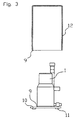
- In a different practical form, the invention is constituted by a pumping group (Fig. 3, n. 1) inside which a delivery indicator (5) and a pressure indicator (6) are attached to the water delivery conduit (3), and above which a top (12) is placed. In this practical solution, the control panel is located on the top of the pump, rather than on its body.
- Further characteristics and advantages will be more evident looking to a favourite but not restrictive form of realization depicted as an example in the attached drawings where:
- Fig. 1 shows a vertical section drawing of the machine (1) constituted by a pump (2) for liquids of any kind, equipped, in this case, with impeller (4), entrance hole (7) for water, water suction conduit (3) and exit hole (8). A delivery indicator, or flow switch, (5) and a pressure indicator, or pressure switch (which is not depicted in this table) are attached to the conduit (3);
- Fig. 2 shows a horizontal section drawing of the machine where the section of the pump (2), the flow switch (5) and the pressure switch (6) are highlighted;
- Fig. 3 shows a schematic possible conformation of the machine constituted by a base (10) equipped with supports (11) where the machine (1) is located, isolated from sounds and vibrations with silent-blocks and/or gaskets (9) which are placed on the base of the top (12) as well.
Claims (9)
- Water pump characterized by the fact that is a body one with:a pressure indicator (6) integrated to the water delivery conduit (3) inside the pump (2), which checks the pressure of the fluid;a flow indicator (5) integrated to the water suction or delivery conduit (3) inside the pump (2) which registers the presence of flow of water inside the pump;a programmed electronic circuit connected with the pressure indicator and the flow indicator, specifically programmed to activate the pump when a certain pressure and/or flow is registered, and to deactivate the pump when a certain pressure is registered and/or in the absence of flow of the fluid, reading the data coming from the pressure indicator and the flow indicator;
- Pump according to claim 1 characterized by the fact that it's equipped with a cooling system of the electric motor, which operates through the passage of the pumped flow around the external surface of the electric tight motor, which, being skimmed by the fluid, cools. This allows the machine to be very silent and effective while working.
- Pump according to claim 1 or 2 characterized by the fact that the programmed electronic circuit analyses the data coming from the pressure switch (6) and/or the flow indicator sensor (5) and activate automatically the pump when some water is required, when it measures a certain flow and/or a prefixed pressure, which is then kept constant.
- Pump according to claim 1, characterized by the fact that comprises a control panel accessible from the outside of the pump, as it is directly attached to the body of the pump, to its top or to a completely separated support, possibly far from the pump.
- Pump according to claim 4 characterized by the fact that the control panel is inserted on the top (12), that works as further acoustic insulator, and is connected to the circuit for the programmed operation of the device.
- Pump according to claim 1, 2 or 3 characterized by the fact that the electronic circuit is programmed so as to allow the pump to work automatically, providing for activating it when the tap is turned on and deactivating it when it's turned off and/or in the absence of water to be sucked, thus avoiding possible damages to the machine.
- Pump according to claim 1 characterized by the fact that the circuit can be programmed in order to carry out further functions according to the producer's or user's needs, always starting from the analysis of the data provided by the pressure switch and the flow indicator.
- Pump according to claim 7 characterized by the fact that the circuit is programmed so that it deactivates the pump automatically when the pump itself turns on and off more than once in short regular periods of time, because of a loss from the pipes of the hydraulic plant.
- Pump according to claim 1 or 2 characterized by the fact that the pumping group, with the pressure-flow switch device attached, is incorporated in a compact block that comprises a control panel.
Applications Claiming Priority (2)
| Application Number | Priority Date | Filing Date | Title |
|---|---|---|---|
| ITPI990047 | 1999-08-06 | ||
| IT1999PI000047A IT1309857B1 (en) | 1999-08-06 | 1999-08-06 | HYDRAULIC MACHINE WITH INTEGRATED AUTOMATIC CONTROL DEVICE |
Publications (2)
| Publication Number | Publication Date |
|---|---|
| EP1074745A1 EP1074745A1 (en) | 2001-02-07 |
| EP1074745B1 true EP1074745B1 (en) | 2005-07-13 |
Family
ID=11394426
Family Applications (1)
| Application Number | Title | Priority Date | Filing Date |
|---|---|---|---|
| EP99123319A Expired - Lifetime EP1074745B1 (en) | 1999-08-06 | 1999-11-23 | Hydraulic machine with automatic control device attached |
Country Status (5)
| Country | Link |
|---|---|
| EP (1) | EP1074745B1 (en) |
| AT (1) | ATE299556T1 (en) |
| DE (1) | DE69926123T2 (en) |
| ES (1) | ES2245813T3 (en) |
| IT (1) | IT1309857B1 (en) |
Cited By (1)
| Publication number | Priority date | Publication date | Assignee | Title |
|---|---|---|---|---|
| EP1429034A2 (en) | 2002-12-10 | 2004-06-16 | Wilo Ag | Thermally insulated motor pump unit |
Families Citing this family (10)
| Publication number | Priority date | Publication date | Assignee | Title |
|---|---|---|---|---|
| DE10111739A1 (en) * | 2001-03-12 | 2002-10-02 | Gardena Kress & Kastner Gmbh | pump unit |
| EP1342921A1 (en) * | 2002-03-05 | 2003-09-10 | Ergon S.r.l. | Pump with integral flow sensor |
| EP1775476A1 (en) * | 2005-10-13 | 2007-04-18 | Alessio Pescaglini | Control device for motor pumps |
| GB0703081D0 (en) * | 2007-02-16 | 2007-03-28 | Salamander Pumped Shower Syste | Improvements in water supply systems |
| ITTO20090598A1 (en) * | 2009-07-31 | 2011-02-01 | Sema Elettronica S R L | DEVICE FOR EXTRACTION OF WATER FROM THE SUBSUBLE |
| US8920131B2 (en) * | 2010-12-13 | 2014-12-30 | A.Y. Mcdonald Mfg. Co. | Pump control and method |
| DK2990653T3 (en) * | 2014-08-29 | 2017-03-13 | Pedrollo Spa | A DEVICE FOR CONTROLING A START AND STOP OF AN ELECTRIC MOTOR OF A MOTOR POWER PUMP |
| IT201600082296A1 (en) * | 2016-08-04 | 2018-02-04 | Enrico Raddi | IMPROVED IMPERSION |
| US10697453B2 (en) * | 2017-02-16 | 2020-06-30 | Liquid Controls Llc | Liquid fuel delivery comprising a pump to deliver liquid fuel from a storage source to a delivery location and a controller mitigating power to operate the pump on the basis of a predetermined liquid threshold at the pump inlet |
| IT202300001626A1 (en) * | 2023-02-01 | 2024-08-01 | Dab Pumps Spa | PRESSURE DETECTION DEVICE FOR AN ELECTRIC PUMP AND RELATED ELECTRIC PUMP EQUIPPED WITH IT |
Family Cites Families (6)
| Publication number | Priority date | Publication date | Assignee | Title |
|---|---|---|---|---|
| DE2244275C3 (en) * | 1972-09-09 | 1975-09-04 | Frankl & Kirchner, Fabrik Fuer Elektromotoren U. Elektrische Apparate, 6830 Schwetzingen | Encapsulated collector motor for a pump unit |
| US5135031A (en) * | 1989-09-25 | 1992-08-04 | Vickers, Incorporated | Power transmission |
| CA2101170A1 (en) * | 1991-01-22 | 1992-07-23 | Geoffrey R. Percival | Safety device |
| US5354182A (en) * | 1993-05-17 | 1994-10-11 | Vickers, Incorporated | Unitary electric-motor/hydraulic-pump assembly with noise reduction features |
| DE19503403A1 (en) * | 1995-02-02 | 1996-08-08 | Ritec Srl | Control device for a water supply system |
| IT1295577B1 (en) * | 1997-02-13 | 1999-05-13 | Hydroservice S R L | DEVICE FOR CONTROL OF A HYDRAULIC PUMP, WITH SELF-ADJUSTING COMPUTER PROPORTIONAL CONTROL |
-
1999
- 1999-08-06 IT IT1999PI000047A patent/IT1309857B1/en active
- 1999-11-23 AT AT99123319T patent/ATE299556T1/en not_active IP Right Cessation
- 1999-11-23 EP EP99123319A patent/EP1074745B1/en not_active Expired - Lifetime
- 1999-11-23 DE DE69926123T patent/DE69926123T2/en not_active Expired - Lifetime
- 1999-11-23 ES ES99123319T patent/ES2245813T3/en not_active Expired - Lifetime
Cited By (1)
| Publication number | Priority date | Publication date | Assignee | Title |
|---|---|---|---|---|
| EP1429034A2 (en) | 2002-12-10 | 2004-06-16 | Wilo Ag | Thermally insulated motor pump unit |
Also Published As
| Publication number | Publication date |
|---|---|
| ITPI990047A1 (en) | 2001-02-06 |
| ITPI990047A0 (en) | 1999-08-06 |
| ATE299556T1 (en) | 2005-07-15 |
| EP1074745A1 (en) | 2001-02-07 |
| DE69926123D1 (en) | 2005-08-18 |
| ES2245813T3 (en) | 2006-01-16 |
| DE69926123T2 (en) | 2006-06-01 |
| IT1309857B1 (en) | 2002-02-05 |
Similar Documents
| Publication | Publication Date | Title |
|---|---|---|
| EP1074745A1 (en) | Hydraulic machine with automatic control device attached | |
| KR940016545A (en) | Flow control device and fluid supply device and treatment device using them | |
| ATE331162T1 (en) | HYDRODYNAMIC CLUTCH ARRANGEMENT HAVING A CLUTCH DEVICE INSIDE THE CLUTCH HOUSING | |
| EP0683322A3 (en) | Pumping device. | |
| SE9801728D0 (en) | Apparatus for supplying a liquid fuel to a burner means | |
| RU2403451C2 (en) | Pump unit to be mounted along line | |
| SE9400881D0 (en) | sealing device | |
| GB0210496D0 (en) | Support platform for integrated system control of an appliance | |
| FI942047A0 (en) | The fluid reservoir | |
| GB2272023A (en) | Pump for ablutionary installations. | |
| FR2813241B1 (en) | DEVICE FOR CONTROLLING THE FLOW OF A FLUID | |
| ES2190323A1 (en) | Engine cooling device | |
| ES1048847Y (en) | SUPPORT FOR AN AXIAL DRIVING DEVICE FOR GASEOUS FLUIDS. | |
| DK0537128T3 (en) | Pump | |
| FR2800852B1 (en) | CEILING HEATING DEVICE | |
| SE466986B (en) | Connector for a bench-top dishwasher | |
| NO930270D0 (en) | MULTIPHASE PUMP DEVICE | |
| SE9601731D0 (en) | System for draining liquids | |
| SE9102473L (en) | END OF COOLING SYSTEM FOR ACOUSTIC APPLIANCES | |
| TR201806824U5 (en) | Plastic Body Two Way Fluid Diverter Valve | |
| JPH052216U (en) | Shower pressure device | |
| KR960011355A (en) | Drinking water supply | |
| FR2834084B1 (en) | AUTOMATIC FLUID FLOW RATE CONTROLLER OF A FLUID CIRCUIT | |
| ES1044878U (en) | Device applicable to the inner tank cleaning liquids. (Machine-translation by Google Translate, not legally binding) | |
| DE60017597D1 (en) | DEVICE FOR TEMPERATURE CONTROL OF A LIQUID |
Legal Events
| Date | Code | Title | Description |
|---|---|---|---|
| PUAI | Public reference made under article 153(3) epc to a published international application that has entered the european phase |
Free format text: ORIGINAL CODE: 0009012 |
|
| AK | Designated contracting states |
Kind code of ref document: A1 Designated state(s): AT BE CH CY DE DK ES FI FR GB GR IE IT LI LU MC NL PT SE |
|
| AX | Request for extension of the european patent |
Free format text: AL;LT;LV;MK;RO;SI |
|
| 17P | Request for examination filed |
Effective date: 20010312 |
|
| AKX | Designation fees paid |
Free format text: AT BE CH CY DE DK ES FI FR GB GR IE IT LI LU MC NL PT SE |
|
| 17Q | First examination report despatched |
Effective date: 20020923 |
|
| RAP1 | Party data changed (applicant data changed or rights of an application transferred) |
Owner name: LEADER PUMPS GROUP S.P.A. |
|
| GRAP | Despatch of communication of intention to grant a patent |
Free format text: ORIGINAL CODE: EPIDOSNIGR1 |
|
| GRAS | Grant fee paid |
Free format text: ORIGINAL CODE: EPIDOSNIGR3 |
|
| GRAA | (expected) grant |
Free format text: ORIGINAL CODE: 0009210 |
|
| AK | Designated contracting states |
Kind code of ref document: B1 Designated state(s): AT BE CH CY DE DK ES FI FR GB GR IE IT LI LU MC NL PT SE |
|
| PG25 | Lapsed in a contracting state [announced via postgrant information from national office to epo] |
Ref country code: NL Free format text: LAPSE BECAUSE OF FAILURE TO SUBMIT A TRANSLATION OF THE DESCRIPTION OR TO PAY THE FEE WITHIN THE PRESCRIBED TIME-LIMIT Effective date: 20050713 Ref country code: LI Free format text: LAPSE BECAUSE OF FAILURE TO SUBMIT A TRANSLATION OF THE DESCRIPTION OR TO PAY THE FEE WITHIN THE PRESCRIBED TIME-LIMIT Effective date: 20050713 Ref country code: FI Free format text: LAPSE BECAUSE OF FAILURE TO SUBMIT A TRANSLATION OF THE DESCRIPTION OR TO PAY THE FEE WITHIN THE PRESCRIBED TIME-LIMIT Effective date: 20050713 Ref country code: CH Free format text: LAPSE BECAUSE OF FAILURE TO SUBMIT A TRANSLATION OF THE DESCRIPTION OR TO PAY THE FEE WITHIN THE PRESCRIBED TIME-LIMIT Effective date: 20050713 Ref country code: BE Free format text: LAPSE BECAUSE OF FAILURE TO SUBMIT A TRANSLATION OF THE DESCRIPTION OR TO PAY THE FEE WITHIN THE PRESCRIBED TIME-LIMIT Effective date: 20050713 Ref country code: AT Free format text: LAPSE BECAUSE OF FAILURE TO SUBMIT A TRANSLATION OF THE DESCRIPTION OR TO PAY THE FEE WITHIN THE PRESCRIBED TIME-LIMIT Effective date: 20050713 |
|
| REG | Reference to a national code |
Ref country code: GB Ref legal event code: FG4D |
|
| REG | Reference to a national code |
Ref country code: CH Ref legal event code: EP |
|
| REG | Reference to a national code |
Ref country code: IE Ref legal event code: FG4D |
|
| REF | Corresponds to: |
Ref document number: 69926123 Country of ref document: DE Date of ref document: 20050818 Kind code of ref document: P |
|
| PG25 | Lapsed in a contracting state [announced via postgrant information from national office to epo] |
Ref country code: SE Free format text: LAPSE BECAUSE OF FAILURE TO SUBMIT A TRANSLATION OF THE DESCRIPTION OR TO PAY THE FEE WITHIN THE PRESCRIBED TIME-LIMIT Effective date: 20051013 Ref country code: GR Free format text: LAPSE BECAUSE OF FAILURE TO SUBMIT A TRANSLATION OF THE DESCRIPTION OR TO PAY THE FEE WITHIN THE PRESCRIBED TIME-LIMIT Effective date: 20051013 Ref country code: DK Free format text: LAPSE BECAUSE OF FAILURE TO SUBMIT A TRANSLATION OF THE DESCRIPTION OR TO PAY THE FEE WITHIN THE PRESCRIBED TIME-LIMIT Effective date: 20051013 |
|
| PG25 | Lapsed in a contracting state [announced via postgrant information from national office to epo] |
Ref country code: CY Free format text: LAPSE BECAUSE OF FAILURE TO SUBMIT A TRANSLATION OF THE DESCRIPTION OR TO PAY THE FEE WITHIN THE PRESCRIBED TIME-LIMIT Effective date: 20051123 |
|
| PG25 | Lapsed in a contracting state [announced via postgrant information from national office to epo] |
Ref country code: MC Free format text: LAPSE BECAUSE OF NON-PAYMENT OF DUE FEES Effective date: 20051130 Ref country code: LU Free format text: LAPSE BECAUSE OF NON-PAYMENT OF DUE FEES Effective date: 20051130 |
|
| PG25 | Lapsed in a contracting state [announced via postgrant information from national office to epo] |
Ref country code: PT Free format text: LAPSE BECAUSE OF FAILURE TO SUBMIT A TRANSLATION OF THE DESCRIPTION OR TO PAY THE FEE WITHIN THE PRESCRIBED TIME-LIMIT Effective date: 20051219 |
|
| NLV1 | Nl: lapsed or annulled due to failure to fulfill the requirements of art. 29p and 29m of the patents act | ||
| REG | Reference to a national code |
Ref country code: ES Ref legal event code: FG2A Ref document number: 2245813 Country of ref document: ES Kind code of ref document: T3 |
|
| REG | Reference to a national code |
Ref country code: CH Ref legal event code: PL |
|
| PGFP | Annual fee paid to national office [announced via postgrant information from national office to epo] |
Ref country code: IE Payment date: 20060214 Year of fee payment: 7 |
|
| ET | Fr: translation filed | ||
| PLBE | No opposition filed within time limit |
Free format text: ORIGINAL CODE: 0009261 |
|
| STAA | Information on the status of an ep patent application or granted ep patent |
Free format text: STATUS: NO OPPOSITION FILED WITHIN TIME LIMIT |
|
| 26N | No opposition filed |
Effective date: 20060418 |
|
| PG25 | Lapsed in a contracting state [announced via postgrant information from national office to epo] |
Ref country code: IE Free format text: LAPSE BECAUSE OF NON-PAYMENT OF DUE FEES Effective date: 20061123 |
|
| GBPC | Gb: european patent ceased through non-payment of renewal fee |
Effective date: 20061123 |
|
| REG | Reference to a national code |
Ref country code: IE Ref legal event code: MM4A |
|
| PG25 | Lapsed in a contracting state [announced via postgrant information from national office to epo] |
Ref country code: GB Free format text: LAPSE BECAUSE OF NON-PAYMENT OF DUE FEES Effective date: 20061123 |
|
| PGFP | Annual fee paid to national office [announced via postgrant information from national office to epo] |
Ref country code: GB Payment date: 20060117 Year of fee payment: 7 |
|
| REG | Reference to a national code |
Ref country code: FR Ref legal event code: PLFP Year of fee payment: 17 |
|
| REG | Reference to a national code |
Ref country code: DE Ref legal event code: R082 Ref document number: 69926123 Country of ref document: DE Representative=s name: V. BEZOLD & PARTNER PATENTANWAELTE - PARTG MBB, DE Ref country code: DE Ref legal event code: R081 Ref document number: 69926123 Country of ref document: DE Owner name: DAB PUMPS S.P.A., MESTRINO, IT Free format text: FORMER OWNER: LEADER PUMPS GROUP S.P.A., BIENTINA, IT |
|
| REG | Reference to a national code |
Ref country code: ES Ref legal event code: PC2A Owner name: DAB PUMPS S.P.A. Effective date: 20160518 |
|
| REG | Reference to a national code |
Ref country code: FR Ref legal event code: TP Owner name: DAB PUMPS S.P.A., IT Effective date: 20160527 |
|
| REG | Reference to a national code |
Ref country code: FR Ref legal event code: PLFP Year of fee payment: 18 |
|
| REG | Reference to a national code |
Ref country code: FR Ref legal event code: PLFP Year of fee payment: 19 |
|
| PGFP | Annual fee paid to national office [announced via postgrant information from national office to epo] |
Ref country code: DE Payment date: 20181123 Year of fee payment: 20 |
|
| PGFP | Annual fee paid to national office [announced via postgrant information from national office to epo] |
Ref country code: IT Payment date: 20180927 Year of fee payment: 20 Ref country code: ES Payment date: 20181213 Year of fee payment: 20 Ref country code: FR Payment date: 20181121 Year of fee payment: 20 |
|
| REG | Reference to a national code |
Ref country code: DE Ref legal event code: R071 Ref document number: 69926123 Country of ref document: DE |
|
| REG | Reference to a national code |
Ref country code: ES Ref legal event code: FD2A Effective date: 20201201 |
|
| PG25 | Lapsed in a contracting state [announced via postgrant information from national office to epo] |
Ref country code: ES Free format text: LAPSE BECAUSE OF EXPIRATION OF PROTECTION Effective date: 20191124 |