EP1074459A2 - Ligne de fabrication - Google Patents
Ligne de fabrication Download PDFInfo
- Publication number
- EP1074459A2 EP1074459A2 EP00113493A EP00113493A EP1074459A2 EP 1074459 A2 EP1074459 A2 EP 1074459A2 EP 00113493 A EP00113493 A EP 00113493A EP 00113493 A EP00113493 A EP 00113493A EP 1074459 A2 EP1074459 A2 EP 1074459A2
- Authority
- EP
- European Patent Office
- Prior art keywords
- component
- production line
- receiving device
- component carrier
- component carriers
- Prior art date
- Legal status (The legal status is an assumption and is not a legal conclusion. Google has not performed a legal analysis and makes no representation as to the accuracy of the status listed.)
- Granted
Links
Images

Classifications
-
- B—PERFORMING OPERATIONS; TRANSPORTING
- B62—LAND VEHICLES FOR TRAVELLING OTHERWISE THAN ON RAILS
- B62D—MOTOR VEHICLES; TRAILERS
- B62D65/00—Designing, manufacturing, e.g. assembling, facilitating disassembly, or structurally modifying motor vehicles or trailers, not otherwise provided for
- B62D65/02—Joining sub-units or components to, or positioning sub-units or components with respect to, body shell or other sub-units or components
- B62D65/18—Transportation, conveyor or haulage systems specially adapted for motor vehicle or trailer assembly lines
Definitions
- the invention relates to a production line for step-by-step component machining, especially for the gradual assembly of motor vehicle body shells, according to the preamble of claim 1
- the locking units according to DE 41 13 295 A1 trained in the manner of a rotationally positionable drum magazine which is staggered in the drum circumferential direction, in terms of type different recording devices are arranged from which the receiving device required for the respective body type through appropriate rotation control of the drum magazine in the course of Production line is positioned.
- skid systems for vehicle bodies are in the form of so-called Skid systems known, in which the component carrier only in the direction of production transported through the plant and mostly from the last workstation return tunnel below the production line to the The inlet area of the system is transported back and there again into the production line be smuggled in.
- Skid systems must be in addition to the actual one Production line including a separate return path a return conveyor and inlet and outlet-side transfer devices for the recirculated component carriers must be equipped and require one Accordingly, high construction costs and installation space, which is often not Available.
- the object of the invention is a production line of the aforementioned Kind in such a way that a construction type or model change to constructive and simple, space-saving control without interrupting the machining process and without impairing the manufacturing accuracy becomes.
- each locking unit in addition to a set type different reception facilities also to these in fixed Assignment and a at the same positions of the locking unit corresponding number of component carriers with the associated type Includes matching mounts and so alone by gradually reversing the locking units, not only the a recording change required recording facilities, but together with these also the corresponding component carriers one after the other in the production cycle activated and at the same time the then no longer required recording facilities and component carriers are removed from the manufacturing process, whereby without cumbersome retrofitting and with very little construction and Control effort a model variable, high-precision component processing after the shuttle principle is made possible with the further effect that the invention Production line due to the crowded housing of Mounting devices and component carriers on the individual locking units and the elimination of complicated, large-scale change mechanisms has an extremely space-saving and fault-resistant design and already existing, conventional shuttle systems mostly on the can be converted according to the invention.
- a particularly favorable design of the invention exists Claim 2 in that the locking units in the manner of a rotationally positionable Drum magazines are formed and in the drum circumferential direction successive locations, each with a drum-proof pick-up device and a guide mechanism for one associated therewith Component carriers are provided.
- the locking units each contain separate, in Direction of component transfer between component carrier and receiving device limited lifting movement, the component carrier in the conveying direction movably receiving guide profiles, so that it is structurally simple an exact conveying movement and an individual stroke positioning of the Component carrier can be achieved.
- the component carrier in the Guide profiles are preferably according to claim 4 with roller cages equipped.
- particularly preferred embodiment of the invention are all component carriers that have been introduced into the manufacturing operation Claim 5 about individually unlockable couplings to a rigid composite merged, resulting in no interchangeability a structurally very simple and fail-safe, isochronous Movement control of the component carrier taking over the component transport results, the actuation of the individual clutches in terms of control is linked to a change in position of the locking units.
- the drive unit according to claim 7 in structurally and functionally particularly preferred in the stroke direction controllable, the space between adjacent locking units bridging guide profile with a reversible conveyor drive as well a linearly supported in the guide profile, on both sides between successive component carriers are actuated by and commanded by them selectively detachable intermediate carrier.
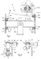
- Each workstation contains a processing device, i.e. a programmable one Tack welding robot 4A, 4B, 4C and an associated locking unit 6A, 6B and 6C, respectively, and between adjacent locking units 6, a drive unit 8 is arranged in each case.
- a processing device i.e. a programmable one Tack welding robot 4A, 4B, 4C and an associated locking unit 6A, 6B and 6C, respectively, and between adjacent locking units 6, a drive unit 8 is arranged in each case.
- the individual locking units are 6 each designed in the manner of a rotatable drum magazine, at which at points offset in the drum circumferential direction, namely in the embodiment shown on the top and bottom, in each case a receiving device 10.1 or 10.2, consisting of a tool plate 12 and centering pin 14 is attached.
- the receiving devices 10 be designed differently depending on the body model. With the two recording devices 10.1 and 10.2 can thus be two different ones Clamp body types at a work station 2. At a Larger number of body models are on the drum magazine in the drum circumferential direction distributes correspondingly many, different types Receiving devices 10 arranged.
- a component carrier 16 is associated with each receiving device 10 also type-specific brackets 18.1 and 18.2 for the same body model like the associated receiving device 10.1 or 10.2 is provided.
- the component carriers 16 each consist of two parallel ones Support rails 20, of which in Fig. 2 the left support rail 20 of the upper Component carrier 16 in the lowered and the right mounting rail 20 in is shown raised state, but which is actually perfect are coupled to each other with the same movement.
- Each mounting rail 20 is designed on the underside in the manner of a toothed rack 22 and on both sides with continuously running in the longitudinal direction of the rail Provided flange portions 24 which, like the enlarged partial view 2 most clearly shows, in corresponding roller cages 26 intervene, which are arranged distributed in the longitudinal direction of the drum Profile pieces 28 are attached so that the mounting rails 20 to the Profile pieces 28 smooth linear movement, but largely otherwise are performed without play.
- the profile pieces 28 and thus also the component carriers 16 are on the drum magazine 6 limited stroke movement and in the lower Stroke position e.g. frictionally, but releasable under the influence of lifting force Drum magazine 6 locked.
- the drive units 8 each contain one by means of a cubic actuator 30 lifting and lowering lifting carriage 32 with rigidly attached guide brackets 34.
- the left drive unit 8 is partially in the lower and partially shown in the upper stroke end position.
- an intermediate support 36 which - with the exception of the brackets 18 - is designed in the same way as the component carrier 16, i.e. out two parallel to one another and of the same cross-section to the mounting rails 20 (shown in Fig.
- intermediate rails 38 which is on the bottom of the rail also designed in the manner of a rack 22 and over lateral flange sections 24 linearly displaceable on (not shown) roller cages of the guide brackets 34 are supported, the length of the intermediate rails 38 essentially the distance between neighboring ones Locking units 6 corresponds.
- the intermediate rails 38 are at each of their ends via a in Fig. 3a in off and shown in Fig. 3b in the engaged state clutch 40 with a adjacent mounting rail 20 of component carrier 16 connectable.
- the Couplings 40 each consist of one at the end of the intermediate rail attached and protruding from this coupling shoe 42, which on the Carrier rail end can be pushed on and then on the coupling shoe 42 attached centering bolt 44 in a form-fitting manner Receiving hole 46 engages at the end of the mounting rail
- the final, rigid Interlock between the rail pieces 20 and 38 is by a Socket pin 48, which by means of a on the guide console 34th attached, control command actuated spindle drive 50 for releasing the Coupling 40 from corresponding through holes 52, 54 of the mounting rail 20 or the clutch shoe 42 can be pulled out and engaged the clutch 40 can be inserted into this and locked on the clutch shoe 42 is when the through bores 52, 54 on the rail pieces 20, 38 are aligned coaxially with the spindle drive 50
- the component carriers 16 and intermediate carriers 36 form thus two parallel, continuous, rigid rail strands attached to the guide brackets 34 of the drive units 8 can be moved in the longitudinal direction of the rail supported and together by means of the stroke actuators 30 can be raised and via a reversible, arranged on the lifting carriage 32 with the rack sections 22 of both rail tracks interact Pinion drive 56 connected to one another in the conveying direction so as to be fixed in motion and to and fro and driven here.
- the component carrier 16 via the stroke actuators 30, the Lift carriage 32 and the intermediate carrier 36 raised so that they the body shells from the respective reception facilities 10.1, and in the upper stroke position by appropriate control of the pinion drives 56 advanced to the next workstation 2, whereupon the Stroke actuators 30 are now activated in the opposite stroke direction and the component carrier 16 together with those located thereon Lower the body-in-white in the subsequent locking unit 6 until that the bodyshells are passed to the receiving devices 10.1 there and can be clamped to the exact position while the component carrier 16 in the lower stroke end position, free of the bodies and by means of the pinion drives 56 opposite to the production direction P again in the previously left locking unit 6 are withdrawn and then in the starting position again.
- the work cycle described repeats itself until the bodyshells work stations 2 in succession have passed through and are then completely welded.
Landscapes
- Engineering & Computer Science (AREA)
- Manufacturing & Machinery (AREA)
- Chemical & Material Sciences (AREA)
- Combustion & Propulsion (AREA)
- Transportation (AREA)
- Mechanical Engineering (AREA)
- Automatic Assembly (AREA)
- Automobile Manufacture Line, Endless Track Vehicle, Trailer (AREA)
Applications Claiming Priority (2)
| Application Number | Priority Date | Filing Date | Title |
|---|---|---|---|
| DE19936607A DE19936607A1 (de) | 1999-08-04 | 1999-08-04 | Fertigungsstraße |
| DE19936607 | 1999-08-04 |
Publications (3)
| Publication Number | Publication Date |
|---|---|
| EP1074459A2 true EP1074459A2 (fr) | 2001-02-07 |
| EP1074459A3 EP1074459A3 (fr) | 2003-04-02 |
| EP1074459B1 EP1074459B1 (fr) | 2005-03-02 |
Family
ID=7917096
Family Applications (1)
| Application Number | Title | Priority Date | Filing Date |
|---|---|---|---|
| EP00113493A Expired - Lifetime EP1074459B1 (fr) | 1999-08-04 | 2000-06-26 | Ligne de fabrication |
Country Status (2)
| Country | Link |
|---|---|
| EP (1) | EP1074459B1 (fr) |
| DE (2) | DE19936607A1 (fr) |
Cited By (1)
| Publication number | Priority date | Publication date | Assignee | Title |
|---|---|---|---|---|
| CN113017201A (zh) * | 2021-04-27 | 2021-06-25 | 东莞市奇裕制鞋机械有限公司 | 一种改进挂篮驱动机构的制鞋生产线 |
Citations (2)
| Publication number | Priority date | Publication date | Assignee | Title |
|---|---|---|---|---|
| DE3500742A1 (de) | 1984-01-11 | 1985-09-26 | Sciaky S.A., Vitry sur Seine, Val-de-Marne | Anlage fuer den zusammenbau und insbesondere das heften von kraftfahrzeug-karrosserien |
| DE4113295A1 (de) | 1990-07-24 | 1992-01-30 | Sciaky Ind S A | Vorrichtung fuer die herstellung von kraftfahrzeug-karosserien |
Family Cites Families (6)
| Publication number | Priority date | Publication date | Assignee | Title |
|---|---|---|---|---|
| GB2059303B (en) * | 1979-09-25 | 1983-06-02 | Nissan Motor | Two-shift automatic assembling apparatus |
| IT1157052B (it) * | 1982-06-16 | 1987-02-11 | Comau Spa | Sistema per la saldatura di carrozzerie di autoveicoli |
| FR2600569B1 (fr) * | 1986-06-27 | 1993-12-03 | Renault Automation | Poste de maintien en position pour lignes capacitaires de carrosseries |
| DE3903518C2 (de) * | 1989-02-07 | 1997-10-02 | Expert Maschbau | Förderbalken-Transportvorrichtung |
| IT1249980B (it) * | 1991-08-07 | 1995-03-30 | Comau Spa | Dispositivo per la saldatura di strutture, quali scocche di autoveicoli o parti di esse, costituite da elementi di lamiera stampata assemblati preliminarmente fra loro in modo labile. |
| DE59408188D1 (de) * | 1993-02-12 | 1999-06-10 | Eisenmann Kg Maschbau | Arbeitsstation für Lackier-Fertigungsstrassen im Fahrzeugbau |
-
1999
- 1999-08-04 DE DE19936607A patent/DE19936607A1/de not_active Withdrawn
-
2000
- 2000-06-26 DE DE50009620T patent/DE50009620D1/de not_active Expired - Fee Related
- 2000-06-26 EP EP00113493A patent/EP1074459B1/fr not_active Expired - Lifetime
Patent Citations (2)
| Publication number | Priority date | Publication date | Assignee | Title |
|---|---|---|---|---|
| DE3500742A1 (de) | 1984-01-11 | 1985-09-26 | Sciaky S.A., Vitry sur Seine, Val-de-Marne | Anlage fuer den zusammenbau und insbesondere das heften von kraftfahrzeug-karrosserien |
| DE4113295A1 (de) | 1990-07-24 | 1992-01-30 | Sciaky Ind S A | Vorrichtung fuer die herstellung von kraftfahrzeug-karosserien |
Cited By (1)
| Publication number | Priority date | Publication date | Assignee | Title |
|---|---|---|---|---|
| CN113017201A (zh) * | 2021-04-27 | 2021-06-25 | 东莞市奇裕制鞋机械有限公司 | 一种改进挂篮驱动机构的制鞋生产线 |
Also Published As
| Publication number | Publication date |
|---|---|
| EP1074459A3 (fr) | 2003-04-02 |
| EP1074459B1 (fr) | 2005-03-02 |
| DE19936607A1 (de) | 2001-02-08 |
| DE50009620D1 (de) | 2005-04-07 |
Similar Documents
| Publication | Publication Date | Title |
|---|---|---|
| DE3506314C2 (fr) | ||
| EP3242755B1 (fr) | Dispositif d'alimentation pour presse plieuse et procédé d'alimentation d'une presse plieuse | |
| EP3579987B1 (fr) | Magasin d'outils de cintrage et procédé de chargement d'une presse-plieuse | |
| EP3023170B1 (fr) | Dispositif de transfert | |
| DE3823947C2 (fr) | ||
| DE3304090A1 (de) | Einrichtung zum montieren bzw. bearbeiten von werkstuecken | |
| WO2006082061A1 (fr) | Procede et dispositif de fabrication de pieces | |
| DE4408449A1 (de) | Transportsystem | |
| WO2008145286A1 (fr) | Poste d'usinage, en particulier de soudage géométrique présentant des armatures de serrage mobiles dotées d'entretoises respectives | |
| DE20104922U1 (de) | Wellrohranlage | |
| EP0671228A2 (fr) | Installation de transport pour pièces à usiner dans une presse | |
| DE4232497C2 (de) | Vorrichtung zur Positionierung einer Karosserie auf einem Förderer | |
| EP0901848A1 (fr) | Presse de transfert avec changement d' outil automatique | |
| EP0621093A1 (fr) | Dispositif de transfert pour transférer des pièces dans un train de presses | |
| DE2851699C2 (de) | Vorrichtung zum Transport eines Werkstückträgers von einer Montage- oder Demontagestation zu einer Werkzeugmaschine und umgekehrt | |
| DD201987A5 (de) | Werkzeugmaschine mit werkstueckzufuehrorganen | |
| WO2002051566A1 (fr) | Presse a etages multiples | |
| EP1074459B1 (fr) | Ligne de fabrication | |
| EP0157353B1 (fr) | Dispositif de transport | |
| DE68908562T2 (de) | System zur übertragung von werkstücken durch eine reihe von arbeitsstationen. | |
| DE3240962C2 (de) | Palettenwechselvorrichtung | |
| EP3490877B1 (fr) | Poste de traitement servant à l'acheminement de cadres de serrage vers une zone de travail et procédé de changement de cadres de serrage | |
| EP0439680A2 (fr) | Procédé et dispositif pour transporter des objets le long d'une ligne de production | |
| EP1401611A1 (fr) | Chaine de montage | |
| DE202020101754U1 (de) | Wechselvorrichtung für einen Wechsel von wenigstens zwei Werkstückauflagen für eine Bearbeitungsmaschine |
Legal Events
| Date | Code | Title | Description |
|---|---|---|---|
| PUAI | Public reference made under article 153(3) epc to a published international application that has entered the european phase |
Free format text: ORIGINAL CODE: 0009012 |
|
| AK | Designated contracting states |
Kind code of ref document: A2 Designated state(s): AT BE CH CY DE DK ES FI FR GB GR IE IT LI LU MC NL PT SE |
|
| AX | Request for extension of the european patent |
Free format text: AL;LT;LV;MK;RO;SI |
|
| PUAL | Search report despatched |
Free format text: ORIGINAL CODE: 0009013 |
|
| AK | Designated contracting states |
Designated state(s): AT BE CH CY DE DK ES FI FR GB GR IE IT LI LU MC NL PT SE Kind code of ref document: A3 Designated state(s): AT BE CH CY DE DK ES FI FR GB GR IE IT LI LU MC NL PT SE |
|
| AX | Request for extension of the european patent |
Extension state: AL LT LV MK RO SI |
|
| 17P | Request for examination filed |
Effective date: 20030416 |
|
| AKX | Designation fees paid |
Designated state(s): DE FR GB IT |
|
| GRAP | Despatch of communication of intention to grant a patent |
Free format text: ORIGINAL CODE: EPIDOSNIGR1 |
|
| GRAS | Grant fee paid |
Free format text: ORIGINAL CODE: EPIDOSNIGR3 |
|
| GRAA | (expected) grant |
Free format text: ORIGINAL CODE: 0009210 |
|
| AK | Designated contracting states |
Kind code of ref document: B1 Designated state(s): DE FR GB IT |
|
| REG | Reference to a national code |
Ref country code: GB Ref legal event code: FG4D Free format text: NOT ENGLISH |
|
| GBT | Gb: translation of ep patent filed (gb section 77(6)(a)/1977) |
Effective date: 20050302 |
|
| REG | Reference to a national code |
Ref country code: IE Ref legal event code: FG4D Free format text: GERMAN |
|
| REF | Corresponds to: |
Ref document number: 50009620 Country of ref document: DE Date of ref document: 20050407 Kind code of ref document: P |
|
| ET | Fr: translation filed | ||
| PLBE | No opposition filed within time limit |
Free format text: ORIGINAL CODE: 0009261 |
|
| STAA | Information on the status of an ep patent application or granted ep patent |
Free format text: STATUS: NO OPPOSITION FILED WITHIN TIME LIMIT |
|
| 26N | No opposition filed |
Effective date: 20051205 |
|
| PGFP | Annual fee paid to national office [announced via postgrant information from national office to epo] |
Ref country code: DE Payment date: 20060726 Year of fee payment: 7 |
|
| PGFP | Annual fee paid to national office [announced via postgrant information from national office to epo] |
Ref country code: GB Payment date: 20070628 Year of fee payment: 8 |
|
| PGFP | Annual fee paid to national office [announced via postgrant information from national office to epo] |
Ref country code: IT Payment date: 20070628 Year of fee payment: 8 |
|
| PG25 | Lapsed in a contracting state [announced via postgrant information from national office to epo] |
Ref country code: DE Free format text: LAPSE BECAUSE OF NON-PAYMENT OF DUE FEES Effective date: 20080101 |
|
| PGFP | Annual fee paid to national office [announced via postgrant information from national office to epo] |
Ref country code: FR Payment date: 20070628 Year of fee payment: 8 |
|
| GBPC | Gb: european patent ceased through non-payment of renewal fee |
Effective date: 20080626 |
|
| REG | Reference to a national code |
Ref country code: FR Ref legal event code: ST Effective date: 20090228 |
|
| PG25 | Lapsed in a contracting state [announced via postgrant information from national office to epo] |
Ref country code: GB Free format text: LAPSE BECAUSE OF NON-PAYMENT OF DUE FEES Effective date: 20080626 |
|
| PG25 | Lapsed in a contracting state [announced via postgrant information from national office to epo] |
Ref country code: IT Free format text: LAPSE BECAUSE OF NON-PAYMENT OF DUE FEES Effective date: 20080626 Ref country code: FR Free format text: LAPSE BECAUSE OF NON-PAYMENT OF DUE FEES Effective date: 20080630 |