EP1074453A2 - Lenkwinkelsensor - Google Patents
Lenkwinkelsensor Download PDFInfo
- Publication number
- EP1074453A2 EP1074453A2 EP00110867A EP00110867A EP1074453A2 EP 1074453 A2 EP1074453 A2 EP 1074453A2 EP 00110867 A EP00110867 A EP 00110867A EP 00110867 A EP00110867 A EP 00110867A EP 1074453 A2 EP1074453 A2 EP 1074453A2
- Authority
- EP
- European Patent Office
- Prior art keywords
- coding element
- steering angle
- angle sensor
- sensor
- sensor arrays
- Prior art date
- Legal status (The legal status is an assumption and is not a legal conclusion. Google has not performed a legal analysis and makes no representation as to the accuracy of the status listed.)
- Granted
Links
- 238000003491 array Methods 0.000 claims abstract description 22
- 210000001520 comb Anatomy 0.000 description 1
- 230000002996 emotional effect Effects 0.000 description 1
- 238000009434 installation Methods 0.000 description 1
- 238000004519 manufacturing process Methods 0.000 description 1
Images

Classifications
-
- B—PERFORMING OPERATIONS; TRANSPORTING
- B62—LAND VEHICLES FOR TRAVELLING OTHERWISE THAN ON RAILS
- B62D—MOTOR VEHICLES; TRAILERS
- B62D15/00—Steering not otherwise provided for
- B62D15/02—Steering position indicators ; Steering position determination; Steering aids
-
- G—PHYSICS
- G01—MEASURING; TESTING
- G01D—MEASURING NOT SPECIALLY ADAPTED FOR A SPECIFIC VARIABLE; ARRANGEMENTS FOR MEASURING TWO OR MORE VARIABLES NOT COVERED IN A SINGLE OTHER SUBCLASS; TARIFF METERING APPARATUS; MEASURING OR TESTING NOT OTHERWISE PROVIDED FOR
- G01D5/00—Mechanical means for transferring the output of a sensing member; Means for converting the output of a sensing member to another variable where the form or nature of the sensing member does not constrain the means for converting; Transducers not specially adapted for a specific variable
- G01D5/12—Mechanical means for transferring the output of a sensing member; Means for converting the output of a sensing member to another variable where the form or nature of the sensing member does not constrain the means for converting; Transducers not specially adapted for a specific variable using electric or magnetic means
- G01D5/244—Mechanical means for transferring the output of a sensing member; Means for converting the output of a sensing member to another variable where the form or nature of the sensing member does not constrain the means for converting; Transducers not specially adapted for a specific variable using electric or magnetic means influencing characteristics of pulses or pulse trains; generating pulses or pulse trains
- G01D5/249—Mechanical means for transferring the output of a sensing member; Means for converting the output of a sensing member to another variable where the form or nature of the sensing member does not constrain the means for converting; Transducers not specially adapted for a specific variable using electric or magnetic means influencing characteristics of pulses or pulse trains; generating pulses or pulse trains using pulse code
- G01D5/2497—Absolute encoders
-
- G—PHYSICS
- G01—MEASURING; TESTING
- G01D—MEASURING NOT SPECIALLY ADAPTED FOR A SPECIFIC VARIABLE; ARRANGEMENTS FOR MEASURING TWO OR MORE VARIABLES NOT COVERED IN A SINGLE OTHER SUBCLASS; TARIFF METERING APPARATUS; MEASURING OR TESTING NOT OTHERWISE PROVIDED FOR
- G01D5/00—Mechanical means for transferring the output of a sensing member; Means for converting the output of a sensing member to another variable where the form or nature of the sensing member does not constrain the means for converting; Transducers not specially adapted for a specific variable
- G01D5/26—Mechanical means for transferring the output of a sensing member; Means for converting the output of a sensing member to another variable where the form or nature of the sensing member does not constrain the means for converting; Transducers not specially adapted for a specific variable characterised by optical transfer means, i.e. using infrared, visible, or ultraviolet light
- G01D5/32—Mechanical means for transferring the output of a sensing member; Means for converting the output of a sensing member to another variable where the form or nature of the sensing member does not constrain the means for converting; Transducers not specially adapted for a specific variable characterised by optical transfer means, i.e. using infrared, visible, or ultraviolet light with attenuation or whole or partial obturation of beams of light
- G01D5/34—Mechanical means for transferring the output of a sensing member; Means for converting the output of a sensing member to another variable where the form or nature of the sensing member does not constrain the means for converting; Transducers not specially adapted for a specific variable characterised by optical transfer means, i.e. using infrared, visible, or ultraviolet light with attenuation or whole or partial obturation of beams of light the beams of light being detected by photocells
- G01D5/347—Mechanical means for transferring the output of a sensing member; Means for converting the output of a sensing member to another variable where the form or nature of the sensing member does not constrain the means for converting; Transducers not specially adapted for a specific variable characterised by optical transfer means, i.e. using infrared, visible, or ultraviolet light with attenuation or whole or partial obturation of beams of light the beams of light being detected by photocells using displacement encoding scales
- G01D5/34776—Absolute encoders with analogue or digital scales
-
- G—PHYSICS
- G01—MEASURING; TESTING
- G01D—MEASURING NOT SPECIALLY ADAPTED FOR A SPECIFIC VARIABLE; ARRANGEMENTS FOR MEASURING TWO OR MORE VARIABLES NOT COVERED IN A SINGLE OTHER SUBCLASS; TARIFF METERING APPARATUS; MEASURING OR TESTING NOT OTHERWISE PROVIDED FOR
- G01D2205/00—Indexing scheme relating to details of means for transferring or converting the output of a sensing member
- G01D2205/20—Detecting rotary movement
- G01D2205/26—Details of encoders or position sensors specially adapted to detect rotation beyond a full turn of 360°, e.g. multi-rotation
Definitions
- the present application is a Additional registration for registration with the file number 199 36 246.7.
- the invention relates to a steering angle sensor, in particular to determine the steering angle of a vehicle, according to Patent application with the file number DE 199 36 246.7, in particular according to claim 11 of said Patent application.
- the invention is characterized in that several Sensor arrays radially around the axis of rotation of the coding element are arranged.
- the advantage of such an arrangement is that the determination of the Lertk angle can be improved.
- Using an appropriate code can be very fine and structures on the coding elements susceptible to interference avoided become.
- the sensor arrays are identical. This allows especially costs in the manufacture of the sensor arrays be saved.
- the sensor arrays are advantageously in one Scanning module arranged.
- a scanning module can for example, can be manufactured as an interchangeable component.
- the individual Sensor arrays out of phase by an angle ⁇ arranged side by side.
- the size of the angle ⁇ determines the code of the coding elements to be scanned.
- At least one individual sensor of a sensor array for Scanning of the further coding element is provided.
- the radially arranged Sensor arrays only scan one coding element and that another, arranged transversely to the radially Sensor array arranged sensor array is present that is provided for scanning the further coding element. It is advantageously achieved that with a own sensor element scanned the further coding element becomes.
- the further coding element is advantageously a Circular disc segment.
- a circular disk segment can have correspondingly small dimensions, whereby the Installation space of the steering angle sensor is reduced.
- a stepper which at a defined rotation of the one coding element the other Drives coding element.
- Such a stepper can for example, every 360 ° angle of rotation of the steering column be switched; however, it is also conceivable that a Switch the stepping mechanism every 180 ° or is switched at other angles of rotation. A switching on is therefore not an integer number of revolutions advantageous to the problem of a certain blur to avoid the assignment of the switching point.
- a worm gear has the further coding element via a slide drives.
- a worm gear with associated Slider can be inexpensive, space saving and with little Effort can be realized.
- Under worm gear can here a spiral or also helical arranged take-along track of the coding element understood become.
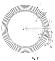
- the Coding element 2 is one in cross section Steering column 6 shown arranged due to a Rotation of the steering wheel of the vehicle rotated about axis 5 becomes.
- the circular disc or ring disc Coding element 2 is non-rotatable with the steering column 6 connected.
- the coding element 2 has a Gray code in Form of four adjacent circular Code tracks 7 on.
- a driving element 12 is located on the coding element 2 arranged, which has two tooth-like projections.
- the entrainment element 12 passes the stationary one Step switch 3, this is around the axis 13 twisted a counting step. Since the stepper 3 with is coupled to the coding element 1 moves due to the Rotation of the stepping mechanism 3 around the coding element 1 a counting step in either one or the other, direction indicated by the double arrow 14.
- the exemplary embodiment shown in FIG. 1 only has a driving element 12. However, it is conceivable that several entrainment elements, for example two or three, in same or different distance on the Coding element 2 are arranged.
- the coding element 1 has only one code track, which represents a suitable Gray code. At the in Fig. 1 shown embodiment is the coding element 1 per full revolution of the steering column 6 by one counting step emotional. Since a steering wheel or the steering column 6 one Turn the vehicle through a maximum of 4 - 6 full revolutions can, the coding element 1 can be made relatively small.
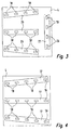
- this shows Scanning module 4 three radially around the axis of rotation 5 of the Coding element 2 arranged sensor arrays 17.
- Fig. 4 shows these sensor arrays 17 in individual parts.
- the Identically designed sensor arrays 17 have five individual sensors 18 and 19 each.
- the first four Individual sensors 18 of each sensor array 17 are for scanning of the four code tracks 7 of the coding element 2 are provided.
- the last individual sensors 19 buttons in operation of the Steering angle sensor the one code track of the coding element 1 from.
- this has Coding element 2 on its side facing the steering column 6 a worm gear 22 in the form of a steering column 6 spiral web.
- the worm drive 22 is coupled to a slide element 23.
- the Slide element points on its the web of Worm drive 22 facing side guide grooves 21 for Pick up the web. Due to the rotation of the Coding element 2 or the worm drive 22 will Slider element 23 is displaced radially to the axis of rotation 5.
- the slide element 23 has the coding element 1 on it facing side a helical toothing 24, the one corresponding ones arranged on the coding element 1 Helical teeth 25 combs.
- FIG. 3 shows another conceivable arrangement of Sensor arrays 26 shown in a scanning module 4.
- the scanning module 4 shown in FIG. 3 has three around the axis 5 radially arranged sensor arrays 26 and one transverse to the Sensor arrays 26 arranged sensor array 27.
- the three Sensor arrays 26 and one sensor array 27 are included constructed identically.
- the sensor arrays 26 with four each Individual sensors 18 serve to scan the four Code tracks 7 of the coding element 2.
- the four individual sensors 19 of the sensor array 27 are for scanning one Code track of the coding element 1 is provided.
- the Sensor arrays 17 arranged out of phase by the angle ⁇ By simultaneously scanning the code tracks 7 and a code track of the coding element 1 can be a code word are formed over which the respective steering angle is determinable.
Landscapes
- Physics & Mathematics (AREA)
- General Physics & Mathematics (AREA)
- Engineering & Computer Science (AREA)
- Chemical & Material Sciences (AREA)
- Combustion & Propulsion (AREA)
- Transportation (AREA)
- Mechanical Engineering (AREA)
- Length Measuring Devices With Unspecified Measuring Means (AREA)
- Transmission And Conversion Of Sensor Element Output (AREA)
- Measurement Of Length, Angles, Or The Like Using Electric Or Magnetic Means (AREA)
- Optical Transform (AREA)
- Length Measuring Devices By Optical Means (AREA)
Abstract
Description
- Fig. 1:
- einen erfindungsgemäßen Lenkwinkelsensor mit Schrittschaltwerk;
- Fig. 2:
- einen anderen erfindungsgemäßen Lenkwinkelsensor mit Schneckentrieb;
- Fig. 3 u. 4:
- zwei verschiedene Ausführungsarten eines Abtastmoduls.
Claims (9)
- Lenkwinkelsensor, insbesondere zur Bestimmung des Lenkwinkels eines Fahrzeuges, nach der Patentanmeldung mit dem Aktenzeichen DE 199 36 246.7, insbesondere nach Anspruch 11 der genannten Patentanmeldung, dadurch gekennzeichnet, dass mehrere Sensorarrays (17, 26) radial um die Drehachse (5) des Codierelements (2) angeordnet sind.
- Lenkwinkelsensor nach Anspruch 1, dadurch gekennzeichnet, dass die Sensorarrays (17, 26, 27) identisch ausgebildet sind.
- Lenkwinkelsensor nach Anspruch 1 oder 2, dadurch gekennzeichnet, dass sämtliche Sensorarrays (17, 26, 27) in einem Abtastmodul (4) angeordnet sind.
- Lenkwinkelsensor nach Anspruch 1, 2 oder 3, dadurch gekennzeichnet, dass die Sensorarrays (17, 26) um einen Winkel δ phasenverschoben nebeneinander angeordnet sind.
- Lenkwinkelsensor nach einem der vorhergehenden Ansprüche, dadurch gekennzeichnet, dass wenigstens ein Einzelsensor (19) eines Sensorarrays (17) zur Abtastung des weiteren Codierelements (1) vorgesehen ist.
- Lenkwinkelsensor nach einem der Ansprüche 1 bis 4, dadurch gekennzeichnet, dass die radial angeordneten Sensorarrays (26) lediglich das eine Codierelement (2) abtasten und dass ein weiteres, quer zu den radial angeordneten Sensoarrays (26) angeordnetes Sensorarray (27) vorhanden ist, das zur Abtastung des weiteren Codierelements (1) vorgesehen ist.
- Lenkwinkelsensor nach einem der vorhergehenden Ansprüche, dadurch gekennzeichnet, dass das weitere Codierelement (1) ein Kreisscheibensegment ist.
- Lenkwinkelsensor nach einem der vorhergehenden Ansprüche, dadurch gekennzeichnet, dass das eine Codierelement (2) ein Schrittschaltwerk (3) schaltet, das bei einer definierten Drehung des einen Codierelements (2) das weitere Codierelement (1) antreibt.
- Lenkwinkelsensor nach einem der Ansprüche 1 bis 7, dadurch gekennzeichnet, dass das eine Codierelement (2) einen schneckentrieb (22) aufweist, der über einen Schieber (23) das weitere Codierelement (1) antreibt.
Applications Claiming Priority (4)
| Application Number | Priority Date | Filing Date | Title |
|---|---|---|---|
| DE1999136246 DE19936246A1 (de) | 1999-07-31 | 1999-07-31 | Lenkwinkelsensor |
| DE19936246 | 1999-07-31 | ||
| DE10009798 | 2000-03-01 | ||
| DE10009798A DE10009798A1 (de) | 1999-07-31 | 2000-03-01 | Lenkwinkelsensor |
Publications (3)
| Publication Number | Publication Date |
|---|---|
| EP1074453A2 true EP1074453A2 (de) | 2001-02-07 |
| EP1074453A3 EP1074453A3 (de) | 2003-11-05 |
| EP1074453B1 EP1074453B1 (de) | 2005-05-04 |
Family
ID=26004607
Family Applications (2)
| Application Number | Title | Priority Date | Filing Date |
|---|---|---|---|
| EP00110867A Expired - Lifetime EP1074453B1 (de) | 1999-07-31 | 2000-05-23 | Lenkwinkelsensor |
| EP00110866A Expired - Lifetime EP1074452B1 (de) | 1999-07-31 | 2000-05-23 | Lenkwinkelsensor |
Family Applications After (1)
| Application Number | Title | Priority Date | Filing Date |
|---|---|---|---|
| EP00110866A Expired - Lifetime EP1074452B1 (de) | 1999-07-31 | 2000-05-23 | Lenkwinkelsensor |
Country Status (3)
| Country | Link |
|---|---|
| EP (2) | EP1074453B1 (de) |
| DE (3) | DE10009798A1 (de) |
| ES (1) | ES2239962T3 (de) |
Cited By (1)
| Publication number | Priority date | Publication date | Assignee | Title |
|---|---|---|---|---|
| JP2010511163A (ja) * | 2006-12-20 | 2010-04-08 | タカタ・ペトリ アーゲー | ステアリング角の絶対値を測定するための光学式ステアリング角センサ |
Families Citing this family (2)
| Publication number | Priority date | Publication date | Assignee | Title |
|---|---|---|---|---|
| DE10110785C2 (de) * | 2001-03-06 | 2003-11-27 | Valeo Schalter & Sensoren Gmbh | Lenkwinkelsensor |
| AU2002249192A1 (en) * | 2002-02-08 | 2003-09-02 | Bishop Innovation Limited | Optical torque and angle sensor |
Citations (1)
| Publication number | Priority date | Publication date | Assignee | Title |
|---|---|---|---|---|
| DE19936246A1 (de) | 1999-07-31 | 2001-02-01 | Valeo Schalter & Sensoren Gmbh | Lenkwinkelsensor |
Family Cites Families (11)
| Publication number | Priority date | Publication date | Assignee | Title |
|---|---|---|---|---|
| US4786891A (en) * | 1986-04-08 | 1988-11-22 | Yokogawa Electric Corporation | Absolute encoder for linear or angular position measurements |
| US5243188A (en) * | 1991-09-26 | 1993-09-07 | Kabushiki Kaisha Tokai Rika Denki Seisakusho | Neutral position detector for steering wheels having a first and second rotors with aligned slots |
| DE4220502C1 (de) * | 1992-06-23 | 1993-12-16 | Stegmann Max Antriebstech | Drehwinkelmeßsystem |
| DE4228719A1 (de) * | 1992-08-28 | 1994-03-03 | Schaeffler Waelzlager Kg | Kapazitiver Lenkwinkelsensor für ein Kraftfahrzeug |
| DE19601965A1 (de) * | 1996-01-20 | 1997-07-24 | Teves Gmbh Alfred | Lenkwinkelsensor mit Umdrehungszählwerk |
| JPH1038557A (ja) * | 1996-07-26 | 1998-02-13 | Alps Electric Co Ltd | 多回転体の回転角検出装置 |
| DE19647705C2 (de) * | 1996-11-11 | 1998-10-08 | Petri Ag | Vorrichtung zur Ermittlung der Winkelstellung des Lenkrades in einem Kraftfahrzeug |
| DE19758104B4 (de) * | 1997-02-13 | 2010-04-15 | Takata-Petri Ag | Adaptiver absoluter Lenkwinkelsensor |
| DE19712869A1 (de) * | 1997-03-27 | 1998-10-01 | Itt Mfg Enterprises Inc | Lenkwinkelsensorsystem mit erhöhter Redundanz |
| DE19819664A1 (de) * | 1998-05-02 | 1999-11-04 | Eaton Controls Gmbh | Vorrichtung zur Bestimmung des Maßes der Verdrehung zwischen zwei Teilen |
| FR2780157B1 (fr) * | 1998-06-18 | 2000-07-21 | Valeo Electronique | Capteur d'angle absolu de la rotation du volant pour vehicule automobile |
-
2000
- 2000-03-01 DE DE10009798A patent/DE10009798A1/de not_active Ceased
- 2000-05-23 EP EP00110867A patent/EP1074453B1/de not_active Expired - Lifetime
- 2000-05-23 DE DE50010208T patent/DE50010208D1/de not_active Expired - Fee Related
- 2000-05-23 EP EP00110866A patent/EP1074452B1/de not_active Expired - Lifetime
- 2000-05-23 DE DE50011492T patent/DE50011492D1/de not_active Expired - Fee Related
- 2000-05-23 ES ES00110867T patent/ES2239962T3/es not_active Expired - Lifetime
Patent Citations (1)
| Publication number | Priority date | Publication date | Assignee | Title |
|---|---|---|---|---|
| DE19936246A1 (de) | 1999-07-31 | 2001-02-01 | Valeo Schalter & Sensoren Gmbh | Lenkwinkelsensor |
Cited By (1)
| Publication number | Priority date | Publication date | Assignee | Title |
|---|---|---|---|---|
| JP2010511163A (ja) * | 2006-12-20 | 2010-04-08 | タカタ・ペトリ アーゲー | ステアリング角の絶対値を測定するための光学式ステアリング角センサ |
Also Published As
| Publication number | Publication date |
|---|---|
| EP1074452A2 (de) | 2001-02-07 |
| DE50011492D1 (de) | 2005-12-08 |
| DE50010208D1 (de) | 2005-06-09 |
| EP1074452A3 (de) | 2004-01-28 |
| ES2239962T3 (es) | 2005-10-16 |
| EP1074452B1 (de) | 2005-11-02 |
| EP1074453A3 (de) | 2003-11-05 |
| EP1074453B1 (de) | 2005-05-04 |
| DE10009798A1 (de) | 2001-09-06 |
Similar Documents
| Publication | Publication Date | Title |
|---|---|---|
| EP0609672B1 (de) | Sicherheitsschalter | |
| DE19722183C2 (de) | Binärinformationsanzeigevorrichtung | |
| EP1627399B1 (de) | Rasteinrichtung für ein dreheinstellbares, elektrisches bauelement | |
| EP2534549B1 (de) | Drehsteller | |
| EP1665312A2 (de) | Drehschalter in einem kraftfahrzeug | |
| WO2010072280A1 (de) | Wälzfräser | |
| EP1074453B1 (de) | Lenkwinkelsensor | |
| DE2817172A1 (de) | Mehrstufiger winkelschrittgeber | |
| DE3238660C2 (de) | Rastwerk, insbesondere für Stufendrehschalter | |
| DE1466208A1 (de) | Fernseheinstellvorrichtung oder UHF-Tuner | |
| EP1673561B1 (de) | Schalteinrichtung | |
| DE19936245A1 (de) | Lenkwinkelsensor | |
| DE4241481C2 (de) | Schalter, insbesondere Lenkstockschalter | |
| DE3140772C2 (de) | Stufendrehschalter | |
| EP1673560B1 (de) | Schalteinrichtung | |
| EP0707541B1 (de) | Antriebsvorrichtung für ein verstellbares teil eines fahrzeuges | |
| DE69703132T2 (de) | Bremssystem | |
| DE60204723T2 (de) | Plattenspieler | |
| DE3013137C2 (de) | ||
| EP0989677B1 (de) | Kodierer zur Umwandlung einer analogen Eingabe in Digitalsignale | |
| DE19936246A1 (de) | Lenkwinkelsensor | |
| EP0951726B1 (de) | Endschaltervorrichtung | |
| EP0805293A1 (de) | Schaltvorrichtung mit Überschaltsperre | |
| DE19641164A1 (de) | Drehimpulsgeber | |
| DE3840529C2 (de) |
Legal Events
| Date | Code | Title | Description |
|---|---|---|---|
| PUAI | Public reference made under article 153(3) epc to a published international application that has entered the european phase |
Free format text: ORIGINAL CODE: 0009012 |
|
| AK | Designated contracting states |
Kind code of ref document: A2 Designated state(s): AT BE CH CY DE DK ES FI FR GB GR IE IT LI LU MC NL PT SE |
|
| AX | Request for extension of the european patent |
Free format text: AL;LT;LV;MK;RO;SI |
|
| PUAL | Search report despatched |
Free format text: ORIGINAL CODE: 0009013 |
|
| AK | Designated contracting states |
Kind code of ref document: A3 Designated state(s): AT BE CH CY DE DK ES FI FR GB GR IE IT LI LU MC NL PT SE |
|
| AX | Request for extension of the european patent |
Extension state: AL LT LV MK RO SI |
|
| 17P | Request for examination filed |
Effective date: 20031129 |
|
| 17Q | First examination report despatched |
Effective date: 20040329 |
|
| AKX | Designation fees paid |
Designated state(s): DE ES FR GB IT |
|
| GRAP | Despatch of communication of intention to grant a patent |
Free format text: ORIGINAL CODE: EPIDOSNIGR1 |
|
| GRAS | Grant fee paid |
Free format text: ORIGINAL CODE: EPIDOSNIGR3 |
|
| GRAA | (expected) grant |
Free format text: ORIGINAL CODE: 0009210 |
|
| AK | Designated contracting states |
Kind code of ref document: B1 Designated state(s): DE ES FR GB IT |
|
| REG | Reference to a national code |
Ref country code: GB Ref legal event code: FG4D Free format text: NOT ENGLISH |
|
| REG | Reference to a national code |
Ref country code: IE Ref legal event code: FG4D Free format text: LANGUAGE OF EP DOCUMENT: GERMAN |
|
| REF | Corresponds to: |
Ref document number: 50010208 Country of ref document: DE Date of ref document: 20050609 Kind code of ref document: P |
|
| GBT | Gb: translation of ep patent filed (gb section 77(6)(a)/1977) |
Effective date: 20050525 |
|
| REG | Reference to a national code |
Ref country code: ES Ref legal event code: FG2A Ref document number: 2239962 Country of ref document: ES Kind code of ref document: T3 |
|
| PLBE | No opposition filed within time limit |
Free format text: ORIGINAL CODE: 0009261 |
|
| STAA | Information on the status of an ep patent application or granted ep patent |
Free format text: STATUS: NO OPPOSITION FILED WITHIN TIME LIMIT |
|
| ET | Fr: translation filed | ||
| 26N | No opposition filed |
Effective date: 20060207 |
|
| PGFP | Annual fee paid to national office [announced via postgrant information from national office to epo] |
Ref country code: DE Payment date: 20080514 Year of fee payment: 9 Ref country code: ES Payment date: 20080522 Year of fee payment: 9 |
|
| PGFP | Annual fee paid to national office [announced via postgrant information from national office to epo] |
Ref country code: IT Payment date: 20080528 Year of fee payment: 9 |
|
| PGFP | Annual fee paid to national office [announced via postgrant information from national office to epo] |
Ref country code: GB Payment date: 20080506 Year of fee payment: 9 |
|
| GBPC | Gb: european patent ceased through non-payment of renewal fee |
Effective date: 20090523 |
|
| REG | Reference to a national code |
Ref country code: FR Ref legal event code: ST Effective date: 20100129 |
|
| PG25 | Lapsed in a contracting state [announced via postgrant information from national office to epo] |
Ref country code: FR Free format text: LAPSE BECAUSE OF NON-PAYMENT OF DUE FEES Effective date: 20090602 |
|
| PGFP | Annual fee paid to national office [announced via postgrant information from national office to epo] |
Ref country code: FR Payment date: 20080430 Year of fee payment: 9 |
|
| PG25 | Lapsed in a contracting state [announced via postgrant information from national office to epo] |
Ref country code: GB Free format text: LAPSE BECAUSE OF NON-PAYMENT OF DUE FEES Effective date: 20090523 |
|
| PG25 | Lapsed in a contracting state [announced via postgrant information from national office to epo] |
Ref country code: DE Free format text: LAPSE BECAUSE OF NON-PAYMENT OF DUE FEES Effective date: 20091201 |
|
| REG | Reference to a national code |
Ref country code: ES Ref legal event code: FD2A Effective date: 20090525 |
|
| PG25 | Lapsed in a contracting state [announced via postgrant information from national office to epo] |
Ref country code: ES Free format text: LAPSE BECAUSE OF NON-PAYMENT OF DUE FEES Effective date: 20090525 |
|
| PG25 | Lapsed in a contracting state [announced via postgrant information from national office to epo] |
Ref country code: IT Free format text: LAPSE BECAUSE OF NON-PAYMENT OF DUE FEES Effective date: 20090523 |