EP1074296A1 - Garnissage ordonné pour échange de chaleur et de masse - Google Patents
Garnissage ordonné pour échange de chaleur et de masse Download PDFInfo
- Publication number
- EP1074296A1 EP1074296A1 EP00116188A EP00116188A EP1074296A1 EP 1074296 A1 EP1074296 A1 EP 1074296A1 EP 00116188 A EP00116188 A EP 00116188A EP 00116188 A EP00116188 A EP 00116188A EP 1074296 A1 EP1074296 A1 EP 1074296A1
- Authority
- EP
- European Patent Office
- Prior art keywords
- layer
- pack
- packing
- ordered
- liquid
- Prior art date
- Legal status (The legal status is an assumption and is not a legal conclusion. Google has not performed a legal analysis and makes no representation as to the accuracy of the status listed.)
- Granted
Links
Images


Classifications
-
- F—MECHANICAL ENGINEERING; LIGHTING; HEATING; WEAPONS; BLASTING
- F28—HEAT EXCHANGE IN GENERAL
- F28C—HEAT-EXCHANGE APPARATUS, NOT PROVIDED FOR IN ANOTHER SUBCLASS, IN WHICH THE HEAT-EXCHANGE MEDIA COME INTO DIRECT CONTACT WITHOUT CHEMICAL INTERACTION
- F28C3/00—Other direct-contact heat-exchange apparatus
- F28C3/06—Other direct-contact heat-exchange apparatus the heat-exchange media being a liquid and a gas or vapour
- F28C3/08—Other direct-contact heat-exchange apparatus the heat-exchange media being a liquid and a gas or vapour with change of state, e.g. absorption, evaporation, condensation
-
- B—PERFORMING OPERATIONS; TRANSPORTING
- B01—PHYSICAL OR CHEMICAL PROCESSES OR APPARATUS IN GENERAL
- B01J—CHEMICAL OR PHYSICAL PROCESSES, e.g. CATALYSIS OR COLLOID CHEMISTRY; THEIR RELEVANT APPARATUS
- B01J19/00—Chemical, physical or physico-chemical processes in general; Their relevant apparatus
- B01J19/32—Packing elements in the form of grids or built-up elements for forming a unit or module inside the apparatus for mass or heat transfer
-
- B—PERFORMING OPERATIONS; TRANSPORTING
- B01—PHYSICAL OR CHEMICAL PROCESSES OR APPARATUS IN GENERAL
- B01J—CHEMICAL OR PHYSICAL PROCESSES, e.g. CATALYSIS OR COLLOID CHEMISTRY; THEIR RELEVANT APPARATUS
- B01J2219/00—Chemical, physical or physico-chemical processes in general; Their relevant apparatus
- B01J2219/32—Details relating to packing elements in the form of grids or built-up elements for forming a unit of module inside the apparatus for mass or heat transfer
- B01J2219/322—Basic shape of the elements
- B01J2219/32203—Sheets
- B01J2219/3221—Corrugated sheets
-
- B—PERFORMING OPERATIONS; TRANSPORTING
- B01—PHYSICAL OR CHEMICAL PROCESSES OR APPARATUS IN GENERAL
- B01J—CHEMICAL OR PHYSICAL PROCESSES, e.g. CATALYSIS OR COLLOID CHEMISTRY; THEIR RELEVANT APPARATUS
- B01J2219/00—Chemical, physical or physico-chemical processes in general; Their relevant apparatus
- B01J2219/32—Details relating to packing elements in the form of grids or built-up elements for forming a unit of module inside the apparatus for mass or heat transfer
- B01J2219/322—Basic shape of the elements
- B01J2219/32203—Sheets
- B01J2219/32213—Plurality of essentially parallel sheets
-
- B—PERFORMING OPERATIONS; TRANSPORTING
- B01—PHYSICAL OR CHEMICAL PROCESSES OR APPARATUS IN GENERAL
- B01J—CHEMICAL OR PHYSICAL PROCESSES, e.g. CATALYSIS OR COLLOID CHEMISTRY; THEIR RELEVANT APPARATUS
- B01J2219/00—Chemical, physical or physico-chemical processes in general; Their relevant apparatus
- B01J2219/32—Details relating to packing elements in the form of grids or built-up elements for forming a unit of module inside the apparatus for mass or heat transfer
- B01J2219/322—Basic shape of the elements
- B01J2219/32203—Sheets
- B01J2219/32224—Sheets characterised by the orientation of the sheet
- B01J2219/32227—Vertical orientation
-
- B—PERFORMING OPERATIONS; TRANSPORTING
- B01—PHYSICAL OR CHEMICAL PROCESSES OR APPARATUS IN GENERAL
- B01J—CHEMICAL OR PHYSICAL PROCESSES, e.g. CATALYSIS OR COLLOID CHEMISTRY; THEIR RELEVANT APPARATUS
- B01J2219/00—Chemical, physical or physico-chemical processes in general; Their relevant apparatus
- B01J2219/32—Details relating to packing elements in the form of grids or built-up elements for forming a unit of module inside the apparatus for mass or heat transfer
- B01J2219/322—Basic shape of the elements
- B01J2219/32203—Sheets
- B01J2219/32255—Other details of the sheets
- B01J2219/32258—Details relating to the extremities of the sheets, such as a change in corrugation geometry or sawtooth edges
-
- B—PERFORMING OPERATIONS; TRANSPORTING
- B01—PHYSICAL OR CHEMICAL PROCESSES OR APPARATUS IN GENERAL
- B01J—CHEMICAL OR PHYSICAL PROCESSES, e.g. CATALYSIS OR COLLOID CHEMISTRY; THEIR RELEVANT APPARATUS
- B01J2219/00—Chemical, physical or physico-chemical processes in general; Their relevant apparatus
- B01J2219/32—Details relating to packing elements in the form of grids or built-up elements for forming a unit of module inside the apparatus for mass or heat transfer
- B01J2219/322—Basic shape of the elements
- B01J2219/32203—Sheets
- B01J2219/32265—Sheets characterised by the orientation of blocks of sheets
- B01J2219/32272—Sheets characterised by the orientation of blocks of sheets relating to blocks in superimposed layers
-
- B—PERFORMING OPERATIONS; TRANSPORTING
- B01—PHYSICAL OR CHEMICAL PROCESSES OR APPARATUS IN GENERAL
- B01J—CHEMICAL OR PHYSICAL PROCESSES, e.g. CATALYSIS OR COLLOID CHEMISTRY; THEIR RELEVANT APPARATUS
- B01J2219/00—Chemical, physical or physico-chemical processes in general; Their relevant apparatus
- B01J2219/32—Details relating to packing elements in the form of grids or built-up elements for forming a unit of module inside the apparatus for mass or heat transfer
- B01J2219/324—Composition or microstructure of the elements
- B01J2219/32408—Metal
-
- B—PERFORMING OPERATIONS; TRANSPORTING
- B01—PHYSICAL OR CHEMICAL PROCESSES OR APPARATUS IN GENERAL
- B01J—CHEMICAL OR PHYSICAL PROCESSES, e.g. CATALYSIS OR COLLOID CHEMISTRY; THEIR RELEVANT APPARATUS
- B01J2219/00—Chemical, physical or physico-chemical processes in general; Their relevant apparatus
- B01J2219/32—Details relating to packing elements in the form of grids or built-up elements for forming a unit of module inside the apparatus for mass or heat transfer
- B01J2219/324—Composition or microstructure of the elements
- B01J2219/32466—Composition or microstructure of the elements comprising catalytically active material
-
- Y—GENERAL TAGGING OF NEW TECHNOLOGICAL DEVELOPMENTS; GENERAL TAGGING OF CROSS-SECTIONAL TECHNOLOGIES SPANNING OVER SEVERAL SECTIONS OF THE IPC; TECHNICAL SUBJECTS COVERED BY FORMER USPC CROSS-REFERENCE ART COLLECTIONS [XRACs] AND DIGESTS
- Y10—TECHNICAL SUBJECTS COVERED BY FORMER USPC
- Y10S—TECHNICAL SUBJECTS COVERED BY FORMER USPC CROSS-REFERENCE ART COLLECTIONS [XRACs] AND DIGESTS
- Y10S261/00—Gas and liquid contact apparatus
- Y10S261/72—Packing elements
Definitions
- the invention relates to an orderly pack for heat and mass transfer between a liquid and a gas in a column.
- the two designs differ in terms of the hydrodynamic operating conditions.
- tray columns In the case of tray columns, one is formed on each tray Bubble layer, in which mainly the liquid is the continuous phase and the gas is the disperse phase. Are located between the individual floors there are spaces in which mainly the gas is the continuous phase.
- packing columns is in terms of hydrodynamics Soil columns different. Here it is not the liquid, but the gas that forms continuous phase. The liquid runs as a film over the packs down from.
- Ordered packs are made up of a large number of individual layers of pack elements, such as sheet metal, expanded metal and wire mesh, built up in a regular structure are arranged vertically to each other and usually by fasteners such as metal wires, thin metal rods or Metal strips are held together in a composite.
- pack elements such as sheet metal, expanded metal and wire mesh
- fasteners such as metal wires, thin metal rods or Metal strips are held together in a composite.
- these packing elements themselves have a geometric structure, for example in the form of kinks or circular holes with about 4 to 6 mm Diameter. The openings serve to raise the flood limit of the pack and to enable a higher column load.
- Packs of the types are examples Mellapak ", CY and BX from Sulzer AG, CH-8404 Winterthur, or the types A3, BSH or B1 from Montz GmbH, D-40723 Hilden.
- the kinks of the packing elements of these packs run in a straight line and at an angle of about 30 Inclined by up to 45 ° to the longitudinal axis of the packing
- the kinks of the packing elements lead to a cross-channel structure within the ordered packing.
- Ordered packs which are catalytically active are known in the prior art.
- the packing is, for example, a catalytically active distillation packing in a conventional shape KATAPAK "from Sulzer AG, CH-8404 Winterthur.
- Ordered packs are usually provided as individual pack layers, which are then stacked on top of each other in the column.
- the Pack layers usually have a height of approximately 0.17 m to approximately 0.30 m on.
- the object of the present invention is the performance and the economy of heat and mass transfer columns, especially for distillative purposes, to increase.
- an orderly packing for heat and Mass transfer between a liquid and a gas in a column comprising at least one pack layer with a first, lower and one second, upper end, the packing layer varying over its height, has inner geometry, so that by a suitable adjustment of the Amounts of liquid and gas in a first, in particular lower area of the Pack layer specifically a bubble layer with predominantly disperse gas phase and at the same time in a second, in particular upper area of the pack layer specifically a film flow of the liquid with predominantly continuous Forms gas phase.
- the inner geometry is - in contrast to the ordered packing of the State of the art - not constant over the height of the pack layer.
- the hydrodynamic operating states described can thereby be achieved be that the flow resistance varies over the height of the packing layer.
- the first, possibly lower, region of the pack layer preferably has one greater flow resistance than the second, possibly upper area the packing layer.
- the first area of the pack layer is preferably in a lower one Area of the pack layer and the second area of the pack layer preferably in an upper area of the pack layer.
- the first, possibly lower area and the second, if appropriate, the upper area of the pack layer preferably over the entire area Cross-sectional area of the pack layer.
- the first, lower area of the pack layer can go directly to the bottom of the pack layer and the second, top area the pack layer directly adjacent to the upper end of the pack layer.
- the first, possibly lower closes Area of the pack layer directly to the second, possibly upper area on.
- an ordered pack in which the packing layer touches flat packing elements, especially sheets, expanded metals, wire mesh and knitted fabrics, with kinks has certain courses, the kink courses or tangents to the Kink courses in the first area of the pack layer with a larger angle the longitudinal axis of the pack layer than in the second region of the Packing layer.
- the kink courses or the tangents form particularly preferably to the kink curves of the packing elements in the first area of the Pack layer an angle of about 45 ° to about 75 ° and in the second Range from about 10 ° to about 45 ° with the longitudinal axis of the pack layer.
- All the kink curves or the tangents to the form particularly preferred Kink profiles in the first area of the pack layer form an angle with the Longitudinal axis of the pack layer from about 60 ° to about 70 ° and in the second Range from about 30 ° to about 45 °.
- the kinks can be at least in sections an arcuate or have a straight course.
- the kinks are monotonous running shape so bent that the tangents to the buckling on lower end of the pack layer an angle of about 45 ° to about 75 °, preferably form about 60 ° to about 70 ° with the longitudinal axis of the package layer; this angle of the tangents to the bend gradients increases Values from approximately 10 ° to approximately 45 °, preferably approximately 30 ° to approximately 45 ° Longitudinal axis of the pack layer reduced.
- the orderly pack can also be designed in such a way that the buckling courses are executed in sections straight, the buckling courses in the first Area of the packing layer preferably an angle of approximately 45 ° to approximately 75 °, particularly preferably from about 60 ° to about 70 °, with the longitudinal axis of the Form the packing layer, and the angle of the kink curves upwards one or more steps to values of preferably about 10 ° to about 45 °, particularly preferably about 30 ° to about 45 °, to the longitudinal axis of the Pack position reduced.
- the specific surface area of the ordered packings according to the invention is preferably about 100 to 750 m 2 / m 3 , particularly preferably 250 to 500 m 2 / m 3 .
- the kinks in the packing elements can be sharp or rounded be executed.
- the first area of the pack layer preferably has a height of 0.02 to 0.10 m, more preferably from 0.03 to 0.10 m and particularly preferably from 0.03 to 0.05 m.
- the second area of the pack layer preferably has a height of 0.1 to 0.3 m and particularly preferably from 0.15 to 0.2 m.
- the pack layers of the ordered pack according to the invention preferably have a height of 0.05 to 0.40 m, more preferably 0.08 to 0.35 m or 0.10 to 0.25 m and particularly preferably 0.12 to 0.20 m.
- the lower height of the pack layer is preferably provided for tightly packed packs with a specific surface area of about 500 to about 750 m 2 / m 3 , the higher value for coarser packs with about 100 to about 500 m 2 / m 3 .
- the liquid load on the ordered packing is preferably between about 0.2 to 50 m 3 / m 2 h.
- the pressure drop of the packing according to the invention is preferably about 2 to 10 mbar / m.
- the packing elements preferably have a sheet thickness of approximately 0.1 mm.
- the packing layer has packing elements
- the packing elements are at least part of the Packing elements at the lower end and / or upper end of the pack layer bent like a flap.
- the packing elements preferably have lower end and / or upper end of the pack layer at defined intervals, which preferably correspond to approximately half the crease width, incisions, see above that tabs can be bent in different directions.
- the tabs are preferably alternating on both sides of the packing element turned.
- the depth of the incisions is preferably 3 to 8 mm.
- the angle that the bent tabs form with the packing element is preferably about 110 to 150 °, so that the tabs in the Package layer are aligned approximately horizontally.
- the lateral extension of the Tabs are chosen so that about 30 to 60% of the flow cross section be blocked. Only every second successive is preferred Packing element bent sideways to ensure adequate mechanical To ensure the stability of the stacked pack layers.
- the packing layer also has packing elements strips at least between at least some of the packing elements Metal sheet arranged. These are preferably flat.
- the Stripes are preferably located at the lower end of the pack layer. You can one or arranged on both sides of the packing elements and preferably on these be attached.
- the strips are particularly preferred by spot welding attached to the packing elements.
- the strips preferably have a height from about 15 to 25 mm.
- One end of the strip, preferably the top of the Strip is preferably bent laterally by about 2 to about 5 mm.
- the side The strip is preferably bent between the bends of the Packing elements. The strips can be bent sideways during assembly the packing elements are made into a packing layer.
- the present invention includes another preferred embodiment in which which the packing layer from a combination of at least a first and a second partial pack layer is composed, the first Subpackage layer and the second subpackage layer with regard to their inner Differentiate geometry from each other.
- the first is in the pack position Partial pack layer preferably arranged below the second partial pack layer.
- the first and second partial pack layers are particularly preferred directly arranged one on top of the other, the first partial pack layer the lower and the second partial pack layer forms the upper partial pack layer.
- the partial pack layers are preferably designed so that their internal geometry does not exceed their Height varies.
- the first, possibly lower, partial pack layer preferably has a height of 0.02 to 0.10 m and particularly preferably from 0.03 to 0.05 m, on.
- the second, possibly upper, partial pack layer preferably has a height of 0.05 to 0.40 m, particularly preferably from 0.10 to 0.25 m.
- the Flow resistance of the first subpackage layer per meter height is preferred about 1.2 to about 5 times, particularly preferably about 1.5 to about 2.5 times so high as the flow resistance of the second subpackage layer.
- Sit down Partial pack layers of pack elements with kinks together, so the Flow resistance of the partial packing layers can be set by the Angle that the kink curves or tangents to the kink curves with the Form the longitudinal axis of the pack layer. The larger this angle, the higher the flow resistance.
- the partial pack layers of packing elements are composed with kinks, the kink curves or Tangents to the kink courses of the first partial pack layer a larger one Form an angle with the longitudinal axis of the pack layer, as the kink curves or Tangents of the buckling courses of the second subpackage layer. Preferred angles have already been mentioned above, to which reference is made here.
- the first region of the pack layer mentioned above corresponds to that here mentioned first partial pack layer and the aforementioned second area the pack layer of the second partial pack layer mentioned here.
- the Flow resistance of the partial packing layers can also be caused by the Size of the specific packing surface per volume can be achieved.
- the partial pack layers each have different specific surfaces Volume on.
- the first, if appropriate lower, particularly preferably Partial pack layer a higher specific surface area per volume than that second, possibly upper, partial pack layer.
- the specific one Surface of the first, optionally lower partial pack layer preferably around 20 to 100%, particularly preferably 30 to 60% larger than that of the second, if necessary, top layer of packaging.
- the first, possibly lower, partial pack layer Wire mesh made. This enables a targeted setting of the Liquid content by changing the heating output.
- the partial pack layers are preferably rotated relative to one another by 45 ° to 90 °.
- the packing elements can be a thin layer of precious metal catalysts exhibit. This plays a role when in a column with the invention Pack in addition to the heat and / or mass transfer also catalyzed Reactions should take place.
- a method is furthermore for heat and / or mass transfer between a liquid and a gas provided in a column in which the liquid and the gas via a Ordered packing described above, especially in countercurrent, out and the liquid and gas quantities are adjusted so that in a first, in particular lower area of the pack layer Bubble layer with predominantly disperse gas phase and at the same time in one second, in particular the upper area of the pack layer specifically a film flow which forms liquid with a predominantly continuous gas phase.
- the column is preferably operated with a pressure drop of about 5 to about 30 mbar, particularly preferably from about 8 to 12 mbar, per meter of packing height operated.
- the pressure drop can be caused by the amount of liquid and gas as well can be set by the heating power.
- the column is superimposed on one a chemical reaction. It can be homogeneous or be heterogeneously catalyzed or run spontaneously.
- the residence time of the liquid in the column can be selected by measuring the heating power while measuring the Differential pressure can be set specifically.
- Homogeneously catalyzed reactions can, for example, acid catalyzed acetalizations, Acetal splits, esterifications, saponifications and ether formations as well as alcoholate-catalyzed transesterifications.
- An example of a spontaneous The reaction taking place in a distillation column is the separation of Formaldehyde from aqueous or alcoholic solutions.
- the ordered packs according to the invention directly Processes already established in technology with catalytically active material coat and carry out heterogeneously catalyzed reactive distillation. If, for reasons of cost, only parts of the packs with catalytically active Material to be coated, it is favorable, preferably the first, if applicable, lower area of the pack layer, in which mainly the Bubble layer forms to coat, since here particularly good mass transfer conditions available.
- the packs according to the invention are also suitable for reactive distillation in which the packs are coated with a thin layer of noble metal catalysts. Partial hydrogenations can then be carried out in the presence of hydrogen.
- components with triple bonds with high selectivity are particularly preferably hydrogenated with components at a total pressure of 3 to 8 bar, particularly preferably of about 4 bar, from a C 4 hydrocarbon mixture to components with double bonds.
- the separation performance of the ordered packing according to the invention is at adjustment of the hydrodynamic state described up to 60% higher than that Separation performance of ordered packings according to the state of the art. As a result, the required height of the column can be reduced and thus Investment costs can be saved.
- the separation performance of the column is usually characterized as the number of theoretical plates per meter column height (n th / m) or as the height for a theoretical plate (HETP).
- the packs according to the invention open up due to the high liquid content in the pack also areas of application that were previously column columns or Special constructions were reserved. So some chemical Carry out reactions in a particularly advantageous manner in columns using the ordered packs according to the invention are equipped.
- the ordered pack designed and operated according to the invention provides one Transitional form between a packed column with predominantly disperse Liquid phase and a tray column with predominantly continuous Liquid phase.
- a tray column high Mass transfer performance in the bubble layer
- a packing column Prevention of droplet entrainment and additional material exchange at the Packaging surface
- Fig. 1 is a pack layer 1 of an embodiment of an orderly Pack shown according to the present invention.
- the pack layer 1 points a first, lower end 2 and a second, upper end 3. She has one Height H of, for example, 0.2 m.
- the packing layer shows touching, flat packing elements 4 made of kinks (not shown) Tin on.
- the reference number 5 shows the longitudinal axis of the pack layer 1 Packing layer 1 also has a circular cross section.
- the inner geometry of the pack layer 1 varies over its height (not shown).
- the pack layer 1 has a first, lower area 6, the inner one Geometry differs from a second, upper area 7.
- the first, lower area 6 of the packing layer 1 has a greater flow resistance on as the second, upper area 7.
- the first, lower region 6 of the Pack 1 a bubble layer with predominantly disperse gas phase and at the same time in the second, upper area 7 of the pack layer Film flow of the liquid with predominantly continuous gas phase.
- the first, lower area 6 of the pack layer 1 and the second, upper area 7 the packing layer 1 extend over the entire cross-sectional area of the Pack position 1.
- the first, lower area 6 directly adjoins the second, upper area 7.
- the second, upper area 7 of the pack layer 1 abuts the second, upper end 3 of the pack layer 1 and the first, lower Area 6 adjoins the first, lower end 2 of the pack layer 1.
- packing elements 4 arranged one behind the other a pack layer 1 of various embodiments of the ordered pack represented schematically according to the present invention.
- the solid ones Lines show the curvature of the first, third, fifth, etc. packing element 4 and the dashed lines the buckling courses of the second, fourth, sixth etc. packing element 4.
- the packing elements 4 in FIG. 2 have the same height H of, for example, 0.2 m as the packing layer 1.
- the packing elements 4 consist of Metal sheets with kinks 8, whereby the packing layer 1, which of these Pack elements is built, receives a cross channel structure.
- the kinks 8 have a straight line in sections.
- the kink profiles form a larger angle ⁇ with the longitudinal axis 5 of the pack layer 1 as in the second, upper region 7 the pack layer 1.
- the kink curves an angle ⁇ of about 60 ° with the longitudinal axis 5 of Pack position 1.
- the buckling courses form one Angle ⁇ of approximately 30 ° with the longitudinal axis 5 of the pack layer 1.
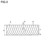
- FIG. 3 schematically shows packing elements 4 of a packing layer 1 of another Embodiment of the ordered pack.
- the packing elements 4 have Bend 8 with continuously curved buckling courses.
- the packing elements 4 have the same height H of, for example, 0.2 m as that Packing position 1.
- the tangents to the kink curves form lower area 6 of the pack layer 1 a larger angle ⁇ with the Longitudinal axis 5 of the pack layer 1 than in the second, upper region 7 of the Packing layer 1.
- the Tangents to the bend gradients an angle of about 45 ° to about 75 ° with the Longitudinal axis 5 of the pack layer 1.
- upper area 7 form the Tangents to the kink profiles with an angle ⁇ of approximately 10 ° to approximately 45 ° the longitudinal axis 5 of the pack layer.
- the kinks 8 have approximately parabolic course.
- FIG. 4 shows a three-dimensional view of a section of a packing element 4 a further embodiment of the pack according to the invention.
- the packing element 4 has kinks 8 in the cutout shown straight course.
- Reference number 5 denotes the longitudinal axis of the Packing layer 1, in which the packing element 4 shown is arranged.
- lower end 2 of the pack layer 1 are at intervals approximately the correspond to half the crease width, about 3 to 8 mm wide incisions in the Packing element 4 introduced and tabs 9 alternately on both sides so bent so that they form angles ⁇ of 110 to 150 ° with the packing element, so that the tabs are aligned approximately horizontally in the pack position.
- the lateral extension of the tabs is chosen so that about 30 to 60% of Flow cross section are blocked.
- packing elements 4 of a packing layer are arranged one behind the other 1 of a further embodiment of the ordered pack.
- the solid lines show the buckling curves of the first, third, fifth, etc. Packing element 4 and the dashed lines the kink curves of the second, fourth etc. packing element 4.
- the packing elements 4 have the same Height H of, for example, 0.2 m as the packing layer 1.
- the Packing elements 4 have straight folds 8.
- the reference number 5 denotes the longitudinal axis of the pack layer 1.
- At the first, lower end 2 of the Packing layer 1 are 4 thin sheet metal strips between the packing elements 15 arranged. The metal sheet strips close directly to the lower one End 2 of the pack layer 1.
- the strips are flat and preferably have a height h of about 15 to 25 mm.
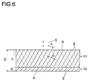
- the pack layer 6 is a pack layer 1 of an embodiment of the invention ordered pack shown in longitudinal section.
- the pack layer 1 consists of two partial pack layers arranged one above the other, a first partial pack layer 10 and a second partial pack layer 11. Both partial pack layers 10, 11 Together they form the height H of the pack layer 1.
- the first partial pack layer 10 forms the lower partial pack layer and the second partial pack layer 11 the upper one Partial packaging layer.
- the first partial pack layer 10 forms the first, lower one Area 6 of the pack layer 1, the second partial pack layer 11 the second, upper area 7 of the pack layer 1.
- Both partial pack layers consist of a plurality of packing elements 4 arranged side by side or one behind the other.
- the packing elements 4 of the partial packing layers 10, 11 consist of sheet metal and have kinks 8 that run in a straight line.
- the solid lines show the buckling courses of the first, third, fifth, etc. packing element 4 and the dashed lines the buckling courses of the second, fourth, sixth etc. Packing element 4.
- the kink curves form with the longitudinal axis 5 of the Pack layer 1 in the first partial pack layer 10 has an angle ⁇ which is larger than the one that the kink curves in the second partial pack layer 11 with the Form longitudinal axis 5.
- the kink profiles form an angle ⁇ of about 60 ° with the longitudinal axis of the pack layer 1.
- the kink profiles form an angle ⁇ of approximately 30 ° with the longitudinal axis of the pack layer 1.
- the first partial pack layer 10 points thereby a greater flow resistance than the second subpackage layer 11.
- the first partial pack layer 10 preferably has a height of 0.02 to 0.10 m, particularly preferably from 0.03 to 0.05 m.
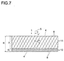
- FIG. 7 shows, like FIG. 6, an embodiment of the ordered according to the invention Pack in longitudinal section, with a pack layer 1 consisting of two Partial pack layers 10, 11 exist.
- the two embodiments of FIGS. 6 and 7 are essentially the same.
- the same reference numbers denote the same parts.
- the buckling profiles form the present embodiment of FIG. 7 in the first and the second Part pack layer 10, 11 the same angle ⁇ with the longitudinal axis 5 of Pack layer 1.
- the lower partial pack layer 10 has a 50% higher specific surface area than the upper partial pack layer 11 the flow resistance in the first, lower partial pack layer 10 is greater than in the second, upper part pack layer 11.
- a suitable setting of the amounts of liquid and gas forms all of the embodiments of the invention described in FIGS. 1 to 7 orderly pack in the first, lower area 6 of the pack layer 1 targeted a bubble layer with predominantly disperse gas phase and at the same time selectively in the second, upper area 7 of the pack layer 1 Film flow of the liquid with predominantly continuous gas phase.
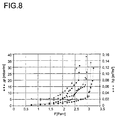
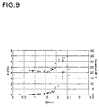
- the differential pressure or pressure loss ⁇ p was measured in mbar / m.
- the dynamic holdup hp [m 3 / m 3 ] is defined as the liquid volume [m 3 ] in the column based on the empty column volume [m 3 ].
- the separation efficiency of the column was determined as the number of theoretical plates per meter column height or packing height (n th / m).
- a glass column with an inner diameter of 0.1 m was used as the test column. Over a height of approximately 0.8 m, it was equipped with 4 layers of an ordered sheet metal packing in a cross-channel structure with a specific surface area of 250 m 2 / m 3 (type Montz B1-250). The orderly package accordingly corresponded to an orderly package of the prior art.
- the packing layers of this orderly packing had packing elements with rectilinear kinks.
- the kink profiles formed an angle of 45 ° with the longitudinal axis of the packing layer or the longitudinal axis of the column.
- the packing elements had circular perforations.
- the air / water system served as the test mixture.
- the column was operated at a pressure of 1 bar and a temperature of about 25 ° C. A liquid quantity of 100 l / h was introduced at the top of the column. The amount of air added at the lower end of the column was varied so that F factors between 0.7 and 3.3, Pa 0.5 resulted.
- the differential pressure ⁇ p and the dynamic hold-up hp were ordered pack measured.
- the results of the measurements are in FIG. 8 represented as diamonds.
- a filled diamond represents the pressure loss ⁇ p, an empty one Check for the holdup hp.
- the dynamic hold-up was only about 2% for F factors ⁇ 3 Pa 0.5 . This increased abruptly with a further increase in the F-factor by less than 10% and led to the flooding of the entire pack. A targeted setting of a dynamic holdup hp of more than 2% was not possible due to this characteristic.
- the pressure drop ⁇ p also shows a very steep increase with higher F factors.
- the experimental setup and operating conditions corresponded to those of the comparative example.
- the column was equipped with an embodiment of an ordered packing according to the present invention. This consisted of 3 pack layers, each composed of a first, lower part pack layer and a second, upper part pack layer.
- the first, lower subpackage layer was an ordered sheet metal packing in a cross-channel structure with a specific surface area of 250 m 2 / m 3 and a height of 0.20 m (type Montz B1-250), as was already used in the comparative example.
- type Montz B1-250 type Montz B1-250
- the second, upper part pack layer was an ordered sheet metal pack with a specific surface area of 500 m 2 / m 3 and a height of 0.03 m (type Montz B1-500).
- This sheet metal packing had packing elements with rectilinear kinks, the kink courses of which formed an angle of 45 ° with the longitudinal axis of the packing layer.
- the packing elements had circular perforations.
- the height H of a pack layer was 0.23 m.
- the three packing layers were arranged one above the other in the column.
- the differential pressure or Pressure drop ⁇ p and the dynamic holdup hp of the ordered packing measured.
- the results of the measurements are shown as squares in FIG. 8 shown.
- a filled square represents the pressure loss ⁇ p, an empty one Square for the holdup hp.
- the dynamic holdup hp was increased by increasing the F factor from 1.5 Raise 2.5 evenly from 2% to 8%.
- the pressure loss correlates well with the holdup hp.
- a desired value can be selected by selecting the pressure drop the holdup hp.
- the experimental set-up and the operating conditions corresponded to those of the comparative example or example 1.
- the column was equipped with an embodiment of an ordered packing according to the present invention, the ordered packing essentially corresponding to that in example 1.
- the ordered pack again consisted of three pack layers, each composed of a first, lower part pack layer and a second, upper part pack layer.
- the first, lower subpackage layer corresponded to that in Example 1 or that of the sheet metal packing used in the comparative example.
- the second, upper partial pack layer consisted of a woven pack with a specific surface area of 500 m 2 / m 3 (type Montz A3-500).
- This fabric pack had packing elements with rectilinear kinks, the kink courses of which formed an angle of 30 ° with the longitudinal axis of the packing layer.
- the packing elements had circular perforations.
- the height of the second, upper partial pack layer was, as in Example 1, 0.03 m.
- the height of a pack layer was accordingly, as in Example 1, 0.23 m.
- the Differential pressure or pressure drop ⁇ p and the dynamic holdup hp measured.
- the results of the measurements are shown as circles in FIG. 8.
- On filled circle stands for the pressure loss ⁇ p, an empty circle for the holdup hp.
- the dynamic holdup was increased by increasing the F-factor from 2.0 to 3.0 be increased evenly from 2% to 10%.
- Example 2 In a test column with a diameter of 0.1 m Distillation experiments with a test mixture of isobutanol and n-butanol a pressure of 1 bar. The column was with a Embodiment of an ordered package equipped, that of Example 2 corresponded.
- the number of plates could n th per meter will be increased by about 50%.
- the desired advantageous operating state could be controlled precisely by the differential pressure or pressure drop ⁇ p.
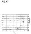
- the experimental setup, the ordered package and the test mixture corresponded those of Example 3. However, the operating pressure of the column was only 0.2 bar.
- Example 3 the differential pressure or pressure drop ⁇ p and the number of theoretical plates n th per meter [m] column / packing height were measured. The results of the measurements are shown in FIG. 10. A filled square stands for the number of theoretical plates n th per meter, an empty square for the pressure loss ⁇ p.
- the liquid could be deliberately dammed up theoretical number of plates per meter [m] column / packing height by approx Can be increased by 50%.
- the measurement of the differential pressure ⁇ p also made it possible here is an exact control of the desired operating state.
Landscapes
- Chemical & Material Sciences (AREA)
- Engineering & Computer Science (AREA)
- Physics & Mathematics (AREA)
- Thermal Sciences (AREA)
- Organic Chemistry (AREA)
- Chemical Kinetics & Catalysis (AREA)
- Mechanical Engineering (AREA)
- General Engineering & Computer Science (AREA)
- Physical Or Chemical Processes And Apparatus (AREA)
- Vaporization, Distillation, Condensation, Sublimation, And Cold Traps (AREA)
- Catalysts (AREA)
- Addition Polymer Or Copolymer, Post-Treatments, Or Chemical Modifications (AREA)
Applications Claiming Priority (2)
| Application Number | Priority Date | Filing Date | Title |
|---|---|---|---|
| DE19936380 | 1999-08-03 | ||
| DE19936380A DE19936380A1 (de) | 1999-08-03 | 1999-08-03 | Geordnete Packung zum Wärme- und Stoffaustausch |
Publications (2)
| Publication Number | Publication Date |
|---|---|
| EP1074296A1 true EP1074296A1 (fr) | 2001-02-07 |
| EP1074296B1 EP1074296B1 (fr) | 2005-10-12 |
Family
ID=7916936
Family Applications (1)
| Application Number | Title | Priority Date | Filing Date |
|---|---|---|---|
| EP00116188A Revoked EP1074296B1 (fr) | 1999-08-03 | 2000-08-02 | Procédé pour échange de chaleur et de masse |
Country Status (6)
| Country | Link |
|---|---|
| US (1) | US6427985B1 (fr) |
| EP (1) | EP1074296B1 (fr) |
| JP (1) | JP4554043B2 (fr) |
| AT (1) | ATE306317T1 (fr) |
| DE (2) | DE19936380A1 (fr) |
| ES (1) | ES2249217T3 (fr) |
Cited By (14)
| Publication number | Priority date | Publication date | Assignee | Title |
|---|---|---|---|---|
| WO2001052980A1 (fr) * | 2000-01-18 | 2001-07-26 | Julius Montz Gmbh | Garniture pour colonnes d"echange de chaleur ou de matiere |
| EP1195563A2 (fr) * | 2000-10-06 | 2002-04-10 | Praxair Technology, Inc. | Système de garnissage structuré permettant une hauteur réduite de colonne de distillation |
| WO2002094432A1 (fr) * | 2001-05-18 | 2002-11-28 | Basf Aktiengesellschaft | Procede de distillation ou de distillation reactive d'un melange contenant au moins un constituant toxique |
| WO2003008092A1 (fr) * | 2001-07-14 | 2003-01-30 | Linde Aktiengesellschaft | Etancheification ordonnee pour transfert de matiere et de chaleur |
| EP1477224A1 (fr) * | 2003-05-16 | 2004-11-17 | Sulzer Chemtech AG | Utilisation d'un garnissage ondulé-croisé composé de fibres métalliques |
| WO2005037428A1 (fr) | 2003-09-20 | 2005-04-28 | Julius Montz Gmbh | Garnissage organise pour l'echange de chaleur et de matiere |
| DE102004013381A1 (de) * | 2004-03-17 | 2005-10-06 | Julius Montz Gmbh | Geordnete Packung für Wärme- und/oder Stoffaustausch |
| DE102004056419A1 (de) * | 2004-11-23 | 2006-05-24 | Julius Montz Gmbh | Geordnete Packung für Wärme und/oder Stoffaustausch |
| DE102006005112A1 (de) * | 2006-02-04 | 2007-08-09 | Hewitech Gmbh & Co. Kg | Kunststofflage für ein Einbauelement zum Einbau in einem Riesenkühler, insbesondere Kühlturm zu Kühlzwecken oder zum Einbau ins Erdreich zu Drainagezwecken |
| EP2269728A1 (fr) * | 2009-06-09 | 2011-01-05 | Basf Se | Utilisation d'emballages ordonnés comportant une ou plusieurs positions d'empilement et une ou plusieurs positions de séparation |
| DE102016222657A1 (de) | 2016-11-17 | 2018-05-17 | OME Technologies GmbH | Verfahren zur Herstellung von Polyoxymethylendimethylethern aus Formaldehyd und Methanol in wässrigen Lösungen |
| US10377689B2 (en) | 2016-11-17 | 2019-08-13 | OME Technologies GmbH | Process for preparing polyoxymethylene dimethyl ethers from formaldehyde and methanol in aqueous solutions |
| DE102020118386A1 (de) | 2020-07-13 | 2022-01-13 | Fraunhofer-Gesellschaft zur Förderung der angewandten Forschung eingetragener Verein | Verfahren zur Herstellung von Polyoxymethylendimethylethern |
| EP4078064A4 (fr) * | 2019-12-20 | 2023-11-29 | Brentwood Industries, Inc. | Feuilles de remplissage et ensembles de supports de remplissage associés |
Families Citing this family (17)
| Publication number | Priority date | Publication date | Assignee | Title |
|---|---|---|---|---|
| DE10010810A1 (de) * | 2000-03-08 | 2001-09-13 | Montz Gmbh Julius | Flüssigkeitsverteiler und Verfahren zum Betreiben |
| FR2813809B1 (fr) * | 2000-09-11 | 2003-07-25 | Air Liquide | Colonne a garnissage d'echange de chaleur et/ou de matiere |
| DE10134389A1 (de) * | 2001-07-04 | 2003-01-16 | Basf Ag | Verfahren zur Herstellung einer salzfreien, wässrigen Hydroxylaminlösung |
| DE10131788A1 (de) * | 2001-07-04 | 2003-01-16 | Basf Ag | Verfahren zur Herstellung einer salzfreien, wässrigen Hydroxylaminlösung |
| DE10131787A1 (de) * | 2001-07-04 | 2003-01-16 | Basf Ag | Verfahren zur Herstellung einer salzfreien, wässrigen Hydroxylaminlösung |
| US6991222B2 (en) * | 2003-03-31 | 2006-01-31 | George Amir Meski | Structured packing with increased capacity |
| SG115648A1 (en) * | 2003-03-31 | 2005-10-28 | Air Prod & Chem | Structured packing with increased capacity |
| DE10337073A1 (de) * | 2003-08-12 | 2005-03-10 | Linde Ag | Verfahren und Vorrichtung zur Herstellung einer geordneten Packung |
| DE10343649A1 (de) * | 2003-09-20 | 2005-04-14 | Julius Montz Gmbh | Geordnete Packung für Wärme- und Stoffaustausch |
| DE102004021985A1 (de) * | 2004-05-04 | 2005-11-24 | Basf Ag | Abdichtung der Anstaulage einer Anstaupackung zum Kolonnenmantel |
| US7267329B2 (en) * | 2005-07-27 | 2007-09-11 | Air Products And Chemicals, Inc. | Alternating conventional and high capacity packing within the same section of an exchange column |
| FR2929532B1 (fr) * | 2008-04-07 | 2010-12-31 | Air Liquide | Colonne a garnissage d'echange de chaleur et/ou matiere |
| US8361432B2 (en) * | 2010-12-08 | 2013-01-29 | Fluor Enterprises, Inc. | Reactor, a retained catalyst structure, and a method for improving decomposition of polysulfides and removal of hydrogen sulfide in liquid sulfur |
| CA2756362C (fr) * | 2010-12-22 | 2018-07-31 | Sulzer Chemtech Ag | Methode de transfert de masse, emballage structure et emballage de transfert de masse pour une faible charge de liquide |
| WO2013036859A1 (fr) | 2011-09-07 | 2013-03-14 | Carbon Engineering Limited Partnership | Capture de gaz cible |
| US9162206B2 (en) | 2013-12-05 | 2015-10-20 | Exxonmobil Research And Engineering Company | Reactor bed component for securing rigid assemblies |
| CN109745834A (zh) * | 2019-03-07 | 2019-05-14 | 广东南方碳捕集与封存产业中心 | 一种燃煤电厂用填料高度可调节式解吸塔 |
Citations (5)
| Publication number | Priority date | Publication date | Assignee | Title |
|---|---|---|---|---|
| US4186159A (en) * | 1977-05-12 | 1980-01-29 | Sulzer Brothers Limited | Packing element of foil-like material for an exchange column |
| US5124086A (en) * | 1989-06-05 | 1992-06-23 | Munters Eurform Gmbh | Fill pack for heat and mass transfer |
| US5538700A (en) * | 1994-12-22 | 1996-07-23 | Uop | Process and apparatus for controlling temperatures in reactant channels |
| WO1997016247A1 (fr) * | 1995-10-31 | 1997-05-09 | Sulzer Chemtech Ag | Element de remplissage structure |
| US5921109A (en) * | 1998-10-21 | 1999-07-13 | Praxair Technology, Inc. | Method for operating a cryogenic rectification column |
Family Cites Families (17)
| Publication number | Priority date | Publication date | Assignee | Title |
|---|---|---|---|---|
| BE621517A (fr) * | 1963-03-04 | |||
| GB1402883A (en) * | 1972-07-27 | 1975-08-13 | Grimma Masch App Veb | Column filling |
| DE2921270C2 (de) * | 1979-05-25 | 1981-10-08 | Julius Montz Gmbh, 4010 Hilden | Packung für Stoffaustauschkolonnen mit gebogenen Rippen |
| US4518544A (en) * | 1983-01-20 | 1985-05-21 | Baltimore Aircoil Company, Inc. | Serpentine film fill packing for evaporative heat and mass exchange |
| SU1183158A1 (ru) * | 1983-04-07 | 1985-10-07 | Предприятие П/Я Р-6273 | Насадка дл тепломассообменных аппаратов |
| SE459826B (sv) * | 1984-10-03 | 1989-08-07 | Munters Ab Carl | Insatskropp av veckade skikt med speciellt utformade kantpartier |
| DE8904345U1 (fr) * | 1989-04-07 | 1989-05-18 | Streng, Andreas, Dipl.-Ing., 5210 Troisdorf, De | |
| US5147583A (en) * | 1990-12-20 | 1992-09-15 | The Marley Cooling Tower Company | Non-clogging film fill assembly for counterflow water cooling tower |
| DE4122369C1 (en) * | 1991-07-05 | 1992-10-22 | Rainer Richter Gmbh, 5439 Hof, De | Packaging used for heat and mass transfer between liq. and gas - consists of corrugated or folded foil, plate or mat-like packaging elements in zones, in which profiles are inclined to longitudinal axis, etc. |
| ATA166091A (de) * | 1991-08-23 | 1996-02-15 | Faigle Heinz Kg | Füllkörper |
| JPH0791825A (ja) * | 1993-09-20 | 1995-04-07 | Hitachi Ltd | 空気分離装置 |
| US5454988A (en) * | 1994-01-12 | 1995-10-03 | Mitsubishi Corporation | Packing to be used in substance and/or heat exchanging tower |
| CN1091646C (zh) * | 1994-10-04 | 2002-10-02 | 普莱克斯技术有限公司 | 用于精炼系统的高容量结构填料 |
| CN1090055C (zh) | 1995-07-08 | 2002-09-04 | 巴斯福股份公司 | 用于传质塔中的具有低压降和有序结构的织物填料或织物状填料以及使用这些填料的精馏方法 |
| DE19605286A1 (de) | 1996-02-13 | 1997-08-14 | Basf Ag | Druckverlustarme Gewebepackungen oder gewebeähnliche Packungen mit geordneter Struktur zur Verwendung in Stoffaustauschkolonnen |
| US6101841A (en) * | 1998-10-02 | 2000-08-15 | Praxair Technology, Inc. | Cryogenic rectification system with high strength and high capacity packing |
| JP2000249464A (ja) * | 1998-12-28 | 2000-09-14 | Nippon Sanso Corp | 気液接触装置、空気液化分離装置、およびガス分離方法 |
-
1999
- 1999-08-03 DE DE19936380A patent/DE19936380A1/de not_active Withdrawn
-
2000
- 2000-07-25 US US09/625,486 patent/US6427985B1/en not_active Expired - Fee Related
- 2000-07-26 JP JP2000224857A patent/JP4554043B2/ja not_active Expired - Fee Related
- 2000-08-02 EP EP00116188A patent/EP1074296B1/fr not_active Revoked
- 2000-08-02 ES ES00116188T patent/ES2249217T3/es not_active Expired - Lifetime
- 2000-08-02 AT AT00116188T patent/ATE306317T1/de not_active IP Right Cessation
- 2000-08-02 DE DE50011317T patent/DE50011317D1/de not_active Expired - Lifetime
Patent Citations (5)
| Publication number | Priority date | Publication date | Assignee | Title |
|---|---|---|---|---|
| US4186159A (en) * | 1977-05-12 | 1980-01-29 | Sulzer Brothers Limited | Packing element of foil-like material for an exchange column |
| US5124086A (en) * | 1989-06-05 | 1992-06-23 | Munters Eurform Gmbh | Fill pack for heat and mass transfer |
| US5538700A (en) * | 1994-12-22 | 1996-07-23 | Uop | Process and apparatus for controlling temperatures in reactant channels |
| WO1997016247A1 (fr) * | 1995-10-31 | 1997-05-09 | Sulzer Chemtech Ag | Element de remplissage structure |
| US5921109A (en) * | 1998-10-21 | 1999-07-13 | Praxair Technology, Inc. | Method for operating a cryogenic rectification column |
Cited By (20)
| Publication number | Priority date | Publication date | Assignee | Title |
|---|---|---|---|---|
| WO2001052980A1 (fr) * | 2000-01-18 | 2001-07-26 | Julius Montz Gmbh | Garniture pour colonnes d"echange de chaleur ou de matiere |
| EP1195563A2 (fr) * | 2000-10-06 | 2002-04-10 | Praxair Technology, Inc. | Système de garnissage structuré permettant une hauteur réduite de colonne de distillation |
| EP1195563A3 (fr) * | 2000-10-06 | 2003-04-02 | Praxair Technology, Inc. | Système de garnissage structuré permettant une hauteur réduite de colonne de distillation |
| WO2002094432A1 (fr) * | 2001-05-18 | 2002-11-28 | Basf Aktiengesellschaft | Procede de distillation ou de distillation reactive d'un melange contenant au moins un constituant toxique |
| KR100871948B1 (ko) * | 2001-05-18 | 2008-12-08 | 바스프 에스이 | 적어도 하나의 독성 성분을 포함하는 혼합물의 증류 또는반응 증류를 수행하는 방법 |
| WO2003008092A1 (fr) * | 2001-07-14 | 2003-01-30 | Linde Aktiengesellschaft | Etancheification ordonnee pour transfert de matiere et de chaleur |
| EP1477224A1 (fr) * | 2003-05-16 | 2004-11-17 | Sulzer Chemtech AG | Utilisation d'un garnissage ondulé-croisé composé de fibres métalliques |
| NO337609B1 (no) * | 2003-05-16 | 2016-05-09 | Sulzer Chemtech Ag | Anvendelse av en krysspassasjefylling som er laget av et metallstoff |
| US7434794B2 (en) | 2003-05-16 | 2008-10-14 | Florian Kehrer | Mass transfer method using static packings |
| WO2005037428A1 (fr) | 2003-09-20 | 2005-04-28 | Julius Montz Gmbh | Garnissage organise pour l'echange de chaleur et de matiere |
| DE102004013381A1 (de) * | 2004-03-17 | 2005-10-06 | Julius Montz Gmbh | Geordnete Packung für Wärme- und/oder Stoffaustausch |
| WO2006056419A1 (fr) | 2004-11-23 | 2006-06-01 | Julius Montz Gmbh | Garnissage ordonne pour le transfert de chaleur et/ou de matiere |
| DE102004056419A1 (de) * | 2004-11-23 | 2006-05-24 | Julius Montz Gmbh | Geordnete Packung für Wärme und/oder Stoffaustausch |
| DE102006005112A1 (de) * | 2006-02-04 | 2007-08-09 | Hewitech Gmbh & Co. Kg | Kunststofflage für ein Einbauelement zum Einbau in einem Riesenkühler, insbesondere Kühlturm zu Kühlzwecken oder zum Einbau ins Erdreich zu Drainagezwecken |
| EP2269728A1 (fr) * | 2009-06-09 | 2011-01-05 | Basf Se | Utilisation d'emballages ordonnés comportant une ou plusieurs positions d'empilement et une ou plusieurs positions de séparation |
| DE102016222657A1 (de) | 2016-11-17 | 2018-05-17 | OME Technologies GmbH | Verfahren zur Herstellung von Polyoxymethylendimethylethern aus Formaldehyd und Methanol in wässrigen Lösungen |
| US10377689B2 (en) | 2016-11-17 | 2019-08-13 | OME Technologies GmbH | Process for preparing polyoxymethylene dimethyl ethers from formaldehyde and methanol in aqueous solutions |
| EP4078064A4 (fr) * | 2019-12-20 | 2023-11-29 | Brentwood Industries, Inc. | Feuilles de remplissage et ensembles de supports de remplissage associés |
| DE102020118386A1 (de) | 2020-07-13 | 2022-01-13 | Fraunhofer-Gesellschaft zur Förderung der angewandten Forschung eingetragener Verein | Verfahren zur Herstellung von Polyoxymethylendimethylethern |
| WO2022013132A1 (fr) | 2020-07-13 | 2022-01-20 | Fraunhofer-Gesellschaft zur Förderung der angewandten Forschung e. V. | Procédé de production d'éthers diméthyliques de polyoxyméthylène |
Also Published As
| Publication number | Publication date |
|---|---|
| DE19936380A1 (de) | 2001-02-08 |
| EP1074296B1 (fr) | 2005-10-12 |
| JP4554043B2 (ja) | 2010-09-29 |
| ES2249217T3 (es) | 2006-04-01 |
| ATE306317T1 (de) | 2005-10-15 |
| US6427985B1 (en) | 2002-08-06 |
| JP2001162160A (ja) | 2001-06-19 |
| DE50011317D1 (de) | 2005-11-17 |
Similar Documents
| Publication | Publication Date | Title |
|---|---|---|
| EP1074296B1 (fr) | Procédé pour échange de chaleur et de masse | |
| WO2002094432A1 (fr) | Procede de distillation ou de distillation reactive d'un melange contenant au moins un constituant toxique | |
| EP2230011B1 (fr) | Emballage structuré | |
| EP1455931B1 (fr) | Dispositif et procede de mise en oeuvre de distillations reactives a catalyse heterogene notamment destinees a la fabrication de pseudoionone | |
| EP0151693B1 (fr) | Colonne d'échange de matière | |
| EP2496342B1 (fr) | Grille de garniture ondulée et garniture ordonnée, constituée de plusieurs grilles de garniture | |
| EP1261404B1 (fr) | Procédé pour opérer un distributeur de liquides | |
| EP2408553A1 (fr) | Appareil de transfert de masse comprenant un garnissage structuré | |
| EP2408552B1 (fr) | Procédé et dispositif destinés au nettoyage de fluides | |
| WO2003047748A1 (fr) | Oxydes metalliques supportes servant de catalyseurs de condensations aldoliques | |
| EP1477224B1 (fr) | Utilisation d'un garnissage ondulé-croisé composé de fibres métalliques | |
| EP2468395A1 (fr) | Procédé d'échange de matière, garnissage structuré et appareil d'échange de matière pour une faible charge de liquide | |
| EP1251958B1 (fr) | Garniture pour colonnes d'echange de chaleur ou de matiere | |
| EP1166867B1 (fr) | Garnissage pour des colonnes de transfert de chaleur et de masse | |
| EP0925109B1 (fr) | Chicanes pour colonnes d'echange de substance | |
| EP1317955B1 (fr) | Dispositif et procédé pour des réactions hétérogènes catalytiques | |
| EP0097345A2 (fr) | Dispositif d'échange de matière et/ou de chaleur et/ou de réaction chimique entre des matières gazéiformes et/ou liquides pour mélanger celles-ci | |
| EP0761303A2 (fr) | Elément de garnissage pour colonnes d'échange de matière ou de chaleur | |
| DE10221761A1 (de) | Packung für Wärme- und Stoffaustausch | |
| DE2511358A1 (de) | Fuellkoerper hoher porositaet fuer gas-fluessigkeits-kontakte und anwendungen solcher fuellkoerper | |
| EP1834693A1 (fr) | Corps de remplissage en tissu | |
| DE10203819C2 (de) | Einbauten für Packungskolonnen | |
| DE10226120A1 (de) | Geträgerte Metalloxide als Katalysatoren für Aldolkondensationen | |
| DE60131339T2 (de) | Strukturierte Packung mit assymetrischem Wellungsmuster | |
| EP2269728B1 (fr) | Utilisation d'emballages ordonnés comportant une ou plusieurs positions d'empilement et une ou plusieurs positions de séparation |
Legal Events
| Date | Code | Title | Description |
|---|---|---|---|
| PUAI | Public reference made under article 153(3) epc to a published international application that has entered the european phase |
Free format text: ORIGINAL CODE: 0009012 |
|
| AK | Designated contracting states |
Kind code of ref document: A1 Designated state(s): AT BE CH CY DE DK ES FI FR GB GR IE IT LI LU MC NL PT SE |
|
| AX | Request for extension of the european patent |
Free format text: AL;LT;LV;MK;RO;SI |
|
| 17P | Request for examination filed |
Effective date: 20010627 |
|
| AKX | Designation fees paid |
Free format text: AT BE CH CY DE DK ES FI FR GB GR IE IT LI LU MC NL PT SE |
|
| RIN1 | Information on inventor provided before grant (corrected) |
Inventor name: STROEZEL, MANFRED Inventor name: KAIBEL, GERD, DR. Inventor name: STAMMER, ACHIM, DR. |
|
| 17Q | First examination report despatched |
Effective date: 20040929 |
|
| RTI1 | Title (correction) |
Free format text: PROCESS FOR HEAT AND MASS EXCHANGE |
|
| GRAP | Despatch of communication of intention to grant a patent |
Free format text: ORIGINAL CODE: EPIDOSNIGR1 |
|
| GRAS | Grant fee paid |
Free format text: ORIGINAL CODE: EPIDOSNIGR3 |
|
| GRAA | (expected) grant |
Free format text: ORIGINAL CODE: 0009210 |
|
| AK | Designated contracting states |
Kind code of ref document: B1 Designated state(s): AT BE CH CY DE DK ES FI FR GB GR IE IT LI LU MC NL PT SE |
|
| PG25 | Lapsed in a contracting state [announced via postgrant information from national office to epo] |
Ref country code: IE Free format text: LAPSE BECAUSE OF FAILURE TO SUBMIT A TRANSLATION OF THE DESCRIPTION OR TO PAY THE FEE WITHIN THE PRESCRIBED TIME-LIMIT Effective date: 20051012 Ref country code: IT Free format text: LAPSE BECAUSE OF FAILURE TO SUBMIT A TRANSLATION OF THE DESCRIPTION OR TO PAY THE FEE WITHIN THE PRESCRIBED TIME-LIMIT;WARNING: LAPSES OF ITALIAN PATENTS WITH EFFECTIVE DATE BEFORE 2007 MAY HAVE OCCURRED AT ANY TIME BEFORE 2007. THE CORRECT EFFECTIVE DATE MAY BE DIFFERENT FROM THE ONE RECORDED. Effective date: 20051012 Ref country code: FI Free format text: LAPSE BECAUSE OF FAILURE TO SUBMIT A TRANSLATION OF THE DESCRIPTION OR TO PAY THE FEE WITHIN THE PRESCRIBED TIME-LIMIT Effective date: 20051012 |
|
| REG | Reference to a national code |
Ref country code: GB Ref legal event code: FG4D Free format text: NOT ENGLISH |
|
| REG | Reference to a national code |
Ref country code: CH Ref legal event code: EP |
|
| REG | Reference to a national code |
Ref country code: IE Ref legal event code: FG4D Free format text: LANGUAGE OF EP DOCUMENT: GERMAN |
|
| REF | Corresponds to: |
Ref document number: 50011317 Country of ref document: DE Date of ref document: 20051117 Kind code of ref document: P |
|
| PG25 | Lapsed in a contracting state [announced via postgrant information from national office to epo] |
Ref country code: DK Free format text: LAPSE BECAUSE OF FAILURE TO SUBMIT A TRANSLATION OF THE DESCRIPTION OR TO PAY THE FEE WITHIN THE PRESCRIBED TIME-LIMIT Effective date: 20060112 Ref country code: SE Free format text: LAPSE BECAUSE OF FAILURE TO SUBMIT A TRANSLATION OF THE DESCRIPTION OR TO PAY THE FEE WITHIN THE PRESCRIBED TIME-LIMIT Effective date: 20060112 Ref country code: GR Free format text: LAPSE BECAUSE OF FAILURE TO SUBMIT A TRANSLATION OF THE DESCRIPTION OR TO PAY THE FEE WITHIN THE PRESCRIBED TIME-LIMIT Effective date: 20060112 |
|
| GBT | Gb: translation of ep patent filed (gb section 77(6)(a)/1977) |
Effective date: 20060125 |
|
| PG25 | Lapsed in a contracting state [announced via postgrant information from national office to epo] |
Ref country code: PT Free format text: LAPSE BECAUSE OF FAILURE TO SUBMIT A TRANSLATION OF THE DESCRIPTION OR TO PAY THE FEE WITHIN THE PRESCRIBED TIME-LIMIT Effective date: 20060313 |
|
| REG | Reference to a national code |
Ref country code: ES Ref legal event code: FG2A Ref document number: 2249217 Country of ref document: ES Kind code of ref document: T3 |
|
| ET | Fr: translation filed | ||
| REG | Reference to a national code |
Ref country code: IE Ref legal event code: FD4D |
|
| PLBI | Opposition filed |
Free format text: ORIGINAL CODE: 0009260 |
|
| PLAB | Opposition data, opponent's data or that of the opponent's representative modified |
Free format text: ORIGINAL CODE: 0009299OPPO |
|
| PLAX | Notice of opposition and request to file observation + time limit sent |
Free format text: ORIGINAL CODE: EPIDOSNOBS2 |
|
| 26 | Opposition filed |
Opponent name: LINDE AKTIENGESELLSCHAFT, WIESBADEN Effective date: 20060712 |
|
| R26 | Opposition filed (corrected) |
Opponent name: LINDE AKTIENGESELLSCHAFT Effective date: 20060712 |
|
| PG25 | Lapsed in a contracting state [announced via postgrant information from national office to epo] |
Ref country code: MC Free format text: LAPSE BECAUSE OF NON-PAYMENT OF DUE FEES Effective date: 20060831 |
|
| NLR1 | Nl: opposition has been filed with the epo |
Opponent name: LINDE AKTIENGESELLSCHAFT, WIESBADEN |
|
| PLBB | Reply of patent proprietor to notice(s) of opposition received |
Free format text: ORIGINAL CODE: EPIDOSNOBS3 |
|
| NLR1 | Nl: opposition has been filed with the epo |
Opponent name: LINDE AKTIENGESELLSCHAFT |
|
| PG25 | Lapsed in a contracting state [announced via postgrant information from national office to epo] |
Ref country code: AT Free format text: LAPSE BECAUSE OF NON-PAYMENT OF DUE FEES Effective date: 20060802 |
|
| RAP2 | Party data changed (patent owner data changed or rights of a patent transferred) |
Owner name: BASF SE |
|
| NLT2 | Nl: modifications (of names), taken from the european patent patent bulletin |
Owner name: BASF SE Effective date: 20080305 |
|
| PG25 | Lapsed in a contracting state [announced via postgrant information from national office to epo] |
Ref country code: LU Free format text: LAPSE BECAUSE OF NON-PAYMENT OF DUE FEES Effective date: 20060802 |
|
| PG25 | Lapsed in a contracting state [announced via postgrant information from national office to epo] |
Ref country code: CY Free format text: LAPSE BECAUSE OF FAILURE TO SUBMIT A TRANSLATION OF THE DESCRIPTION OR TO PAY THE FEE WITHIN THE PRESCRIBED TIME-LIMIT Effective date: 20051012 |
|
| PLCK | Communication despatched that opposition was rejected |
Free format text: ORIGINAL CODE: EPIDOSNREJ1 |
|
| APBM | Appeal reference recorded |
Free format text: ORIGINAL CODE: EPIDOSNREFNO |
|
| APBP | Date of receipt of notice of appeal recorded |
Free format text: ORIGINAL CODE: EPIDOSNNOA2O |
|
| APAH | Appeal reference modified |
Free format text: ORIGINAL CODE: EPIDOSCREFNO |
|
| APBQ | Date of receipt of statement of grounds of appeal recorded |
Free format text: ORIGINAL CODE: EPIDOSNNOA3O |
|
| PGFP | Annual fee paid to national office [announced via postgrant information from national office to epo] |
Ref country code: DE Payment date: 20101029 Year of fee payment: 11 |
|
| PGFP | Annual fee paid to national office [announced via postgrant information from national office to epo] |
Ref country code: CH Payment date: 20110829 Year of fee payment: 12 |
|
| PGFP | Annual fee paid to national office [announced via postgrant information from national office to epo] |
Ref country code: GB Payment date: 20110831 Year of fee payment: 12 Ref country code: FR Payment date: 20110905 Year of fee payment: 12 |
|
| PGFP | Annual fee paid to national office [announced via postgrant information from national office to epo] |
Ref country code: NL Payment date: 20110829 Year of fee payment: 12 |
|
| REG | Reference to a national code |
Ref country code: DE Ref legal event code: R064 Ref document number: 50011317 Country of ref document: DE Ref country code: DE Ref legal event code: R103 Ref document number: 50011317 Country of ref document: DE |
|
| APBU | Appeal procedure closed |
Free format text: ORIGINAL CODE: EPIDOSNNOA9O |
|
| PGFP | Annual fee paid to national office [announced via postgrant information from national office to epo] |
Ref country code: BE Payment date: 20110923 Year of fee payment: 12 Ref country code: ES Payment date: 20110930 Year of fee payment: 12 |
|
| RDAF | Communication despatched that patent is revoked |
Free format text: ORIGINAL CODE: EPIDOSNREV1 |
|
| RDAG | Patent revoked |
Free format text: ORIGINAL CODE: 0009271 |
|
| STAA | Information on the status of an ep patent application or granted ep patent |
Free format text: STATUS: PATENT REVOKED |
|
| REG | Reference to a national code |
Ref country code: CH Ref legal event code: PL |
|
| 27W | Patent revoked |
Effective date: 20120120 |
|
| GBPR | Gb: patent revoked under art. 102 of the ep convention designating the uk as contracting state |
Effective date: 20120120 |
|
| REG | Reference to a national code |
Ref country code: DE Ref legal event code: R107 Ref document number: 50011317 Country of ref document: DE Effective date: 20120621 |
|
| PG25 | Lapsed in a contracting state [announced via postgrant information from national office to epo] |
Ref country code: CH Free format text: LAPSE BECAUSE OF THE APPLICANT RENOUNCES Effective date: 20051012 Ref country code: LI Free format text: LAPSE BECAUSE OF THE APPLICANT RENOUNCES Effective date: 20051012 |
|
| REG | Reference to a national code |
Ref country code: AT Ref legal event code: MA03 Ref document number: 306317 Country of ref document: AT Kind code of ref document: T Effective date: 20120120 |