EP1073231A2 - Signalkodierung zur Übertragung mehrerer digitalen Signale über ein einziges physikalisches Medium - Google Patents
Signalkodierung zur Übertragung mehrerer digitalen Signale über ein einziges physikalisches Medium Download PDFInfo
- Publication number
- EP1073231A2 EP1073231A2 EP00306082A EP00306082A EP1073231A2 EP 1073231 A2 EP1073231 A2 EP 1073231A2 EP 00306082 A EP00306082 A EP 00306082A EP 00306082 A EP00306082 A EP 00306082A EP 1073231 A2 EP1073231 A2 EP 1073231A2
- Authority
- EP
- European Patent Office
- Prior art keywords
- line
- encoded
- signal
- data rate
- signals
- Prior art date
- Legal status (The legal status is an assumption and is not a legal conclusion. Google has not performed a legal analysis and makes no representation as to the accuracy of the status listed.)
- Withdrawn
Links
Images


Classifications
-
- H—ELECTRICITY
- H04—ELECTRIC COMMUNICATION TECHNIQUE
- H04L—TRANSMISSION OF DIGITAL INFORMATION, e.g. TELEGRAPHIC COMMUNICATION
- H04L25/00—Baseband systems
- H04L25/38—Synchronous or start-stop systems, e.g. for Baudot code
- H04L25/40—Transmitting circuits; Receiving circuits
- H04L25/49—Transmitting circuits; Receiving circuits using code conversion at the transmitter; using predistortion; using insertion of idle bits for obtaining a desired frequency spectrum; using three or more amplitude levels ; Baseband coding techniques specific to data transmission systems
- H04L25/4904—Transmitting circuits; Receiving circuits using code conversion at the transmitter; using predistortion; using insertion of idle bits for obtaining a desired frequency spectrum; using three or more amplitude levels ; Baseband coding techniques specific to data transmission systems using self-synchronising codes, e.g. split-phase codes
-
- H—ELECTRICITY
- H04—ELECTRIC COMMUNICATION TECHNIQUE
- H04L—TRANSMISSION OF DIGITAL INFORMATION, e.g. TELEGRAPHIC COMMUNICATION
- H04L25/00—Baseband systems
- H04L25/38—Synchronous or start-stop systems, e.g. for Baudot code
- H04L25/40—Transmitting circuits; Receiving circuits
- H04L25/49—Transmitting circuits; Receiving circuits using code conversion at the transmitter; using predistortion; using insertion of idle bits for obtaining a desired frequency spectrum; using three or more amplitude levels ; Baseband coding techniques specific to data transmission systems
- H04L25/4906—Transmitting circuits; Receiving circuits using code conversion at the transmitter; using predistortion; using insertion of idle bits for obtaining a desired frequency spectrum; using three or more amplitude levels ; Baseband coding techniques specific to data transmission systems using binary codes
-
- H—ELECTRICITY
- H04—ELECTRIC COMMUNICATION TECHNIQUE
- H04L—TRANSMISSION OF DIGITAL INFORMATION, e.g. TELEGRAPHIC COMMUNICATION
- H04L5/00—Arrangements affording multiple use of the transmission path
- H04L5/02—Channels characterised by the type of signal
Definitions
- the present invention relates generally to data transmission. More particularly, the present invention relates to signal encoding to allow for the transmission of multiple digital signals via a single physical medium.
- the amount of information that can be transmitted between two devices is generally limited by the bandwidth of the physical medium interconnecting the two devices.
- the amount of digital data that may be transmitted between two integrated circuits (IC) is limited by the bandwidth of the physical wire connecting the ICs.
- a first data stream may be a high rate primary signal and a second data stream may be a low rate secondary signal.
- the secondary signal may be used, for example, to transmit control information between the devices.
- the bandwidth of the physical connection between the devices limits the amount of data that may be transmitted.
- Data encoding techniques exist which allow for the transmission of both a primary digital signal and a secondary digital signal over a single physical medium.
- United States Patent No. 4,716,563 entitled Demodulation of Auxiliary Low Frequency Channels in Digital Transmission Systems and United States Patent No. 4,972,408 entitled Method and Apparatus for Combining and For Separating a Low Data Rate Digital Channel with or from the High Data Rate Digital Channel of a Transmission Link both disclose techniques for transmitting a low data rate auxiliary digital signal along with a high data rate primary digital signal on a physical transmission medium. Both techniques modulate the low data rate signal so that it may be transmitted along the single transmission medium without interfering with the primary signal.
- One disadvantage of such techniques is that they require modulation of the low data rate signal at the transmitter and demodulation of the low data rate signal at the receiver, thus increasing the cost of the overall system.
- two or more digital signals are encoded using two or more respective line codes, such that the power spectral densities of the encoded signals are substantially orthogonal in the frequency domain. Since the power spectral densities of the encoded signals are substantially orthogonal, the encoded signals may be combined and transmitted via a single physical medium with little or no interference. Appropriate line codes are chosen taking into account the data rates of the two or more digital signals in order to achieve the desired orthogonality.
- a low data rate digital signal and a high data rate digital signal are transmitted via a single physical medium.
- the low data rate digital signal is encoded using a polar non-return-to zero line code and the high data rate digital signal is encoded using a Manchester line code. Due to the characteristics of these line codes, the encoded low data rate digital signal will have high power spectral density in a low frequency range and the encoded high data rate digital signal will have high power spectral density in a high frequency range. Further, the encoded low data rate digital signal will have low power spectral density in the high frequency range and the encoded high data rate digital signal will have low power spectral density in a low frequency range.
- the power spectral densities of the encoded signals are substantially orthogonal and the encoded signals may be combined and transmitted via a single physical medium with little or no interference.
- a first high data rate digital signal, a second low data rate digital signal, and a third low data rate digital signal may be line encoded in accordance with the invention and transmitted via a single physical medium.
- the first high data rate digital signal is encoded using Manchester line coding
- the second low data rate digital signal is encoded using polar non-return-to-zero line coding
- the third low data rate digital signal is encoded using alternate mark inversion line coding.
- the power spectral densities of the encoded signals are substantially orthogonal and the encoded signals may be combined and transmitted via a single physical medium with little or no interference.
- a transmitter for encoding the digital signals includes line coders for line encoding received digital signals and a combiner for combining the encoded signals and transmitting the encoded signals via a single physical medium.
- a receiver for receiving the combined signal includes filters for extracting individual encoded signals and line decoders for receiving the individual encoded signals and decoding them to produce the original digital data signal. Since the line encoded signals have high power spectral densities in different frequency ranges, appropriate filters may be chosen to pass the appropriate encoded signal to the appropriate line decoder.
- a well known method for the transmission of digital data over a physical medium is the use of line codes.
- a line code maps the digital levels 1 and 0 to voltage waveforms such that the digital data may be recovered from the signal received at the receiver with minimal error.
- Many different line codes are known, and each line code has its own distinct characteristics.
- One such characteristic of line codes is the power spectral density (PSD) which describes the relative power contributed by various frequency components.
- a first high data rate digital data signal is encoded using a Manchester line code and a second low data rate digital data signal is encoded using a polar non-return-to-zero (NRZ) line code.
- Line codes are well known in the art and various line codes in accordance with particular embodiments of the invention will be described briefly herein. For further information on line codes, see Modern Digital and Analog Communication Systems , Second Edition, B. P. Lathi, Oxford University Press, 1995, Chapter 3.
- a digital 1 is encoded as +V volts and a digital 0 is encoded as -V volts.
- Polar NRZ is a non-return-to-zero code such that the waveform does not return to 0 volts between symbols.
- An example waveform for the digital signal 10011 encoded using polar NRZ is shown in Fig. 1.
- Fig. 2 shown the normalized PSD for a signal encoded using the polar NRZ line code. As seen from Fig. 2, the PSD has a significant DC (i.e., 0 frequency) component. Further, for a signaling rate of R bps, a bandwidth null occurs at R Hz.
- a Manchester line code is a transition line code wherein waveform transitions between +V and -V encode the digital signal.
- a digital 1 is encoded as a +V ⁇ -V transition
- a digital 0 is encoded as a -V ⁇ +V transition.
- An example waveform for the digital signal 10011 encoded using a Manchester line code is shown in Fig. 3.
- Fig. 4 shown the normalized PSD for a signal encoded using the Manchester line code. As seen from Fig. 4, the PSD has 0 DC component. Further, for a signaling rate of R bps, a bandwidth null occurs at 2R Hz.
- a first low data rate digital signal is encoded using the polar NRZ line code
- a second high data rate digital signal is encoded using the Manchester line code
- the two encoded signals are combined and transmitted over a single physical transmission medium. Due to the characteristics of the line codes, the PSD's of the encoded signals at the chosen data rates are substantially orthogonal, and thus the two encoded signals may be combined and transmitted via a single physical medium without interference. Fig.
- FIG. 5 shows the normalized PSDs for the encoded signals in accordance with this embodiment of the invention in which a high data rate digital signal at a data rate of 4R is encoded using Manchester encoding and a low data rate digital signal at a data rate of R/4 is encoded using polar NRZ encoding.
- the PSD for the polar NRZ encoded signal is shown as curve 502 and the PSD for the Manchester encoded signal is shown as curve 504.
- the high data rate Manchester encoded signal has a low PSD in the low frequency range
- the low data rate polar NRZ encoded signal has a high PSD in the same low frequency range.
- the high data rate Manchester encoded signal has a high PSD in the high frequency range
- the low data rate polar NRZ encoded signal has a low PSD in the same high frequency range. Because of the substantial orthogonality of the PSDs of the two encoded signals, the signals may be combined and transmitted simultaneously over the same physical medium with little or no interference.
- a transmitter 602 receives a low data rate digital signal and a high data rate digital signal.
- the low data rate digital signal is encoded by polar NRZ line coder 604 and the high data rate digital signal is encoded by Manchester line coder 606.
- the two encoded signals are combined by combiner 608 and transmitted via a wire 610 to receiver 620.
- the signal is split and provided to a low-pass filter 622 and a high-pass filter 626.
- the low-pass filter 622 passes the signal in the low frequency range.
- the high data rate encoded signal has a low PSD in the low frequency range, and the low data rate encoded signal has a high PSD in the same low frequency range.
- the output of the low-pass filter 622 is provided to a polar NRZ line decoder 624 for decoding.
- the polar NRZ line decoder 624 will output the low data rate digital signal.
- the high-pass filter 626 passes the signal in the high frequency range.
- the high data rate encoded signal has a high PSD in the high frequency range
- the low data rate encoded signal has a low PSD in the same high frequency range.
- the output of the high-pass filter 626 is provided to a Manchester line decoder 630 for decoding.
- the Manchester line decoder 630 outputs the high data rate digital signal.
- a first high data rate digital signal is encoded using a Manchester line code
- a second low data rate digital signal is encoded using polar non-return-to-zero (NRZ) line code
- a third low data rate digital signal is encoded using an alternate mark inversion (AMI) line code.
- a digital 1 is alternately encoded as +V and -V and a digital 0 is encoded as 0 V.
- An example waveform for the digital signal 10011 encoded using an AMI line code is shown in Fig. 7.
- Fig. 8 shown the normalized PSD for a signal encoded using the AMI line code. As seen from Fig. 8, the PSD has 0 DC component. Further, for a signaling rate of R bps, a bandwidth null occurs at R Hz.
- the AMI line code is well known and is further described in Modern Digital and Analog Communication Systems , Second Edition, B. P. Lathi, Oxford University Press, 1995, p. 171.
- a first low data rate digital signal is encoded using the polar NRZ line code
- a second low data rate digital signal is encoded using the AMI line code
- a third high data rate digital signal is encoded using the Manchester line code
- three encoded signals are combined and transmitted over a single transmission medium. Due to the characteristics of the line codes in combination with chosen data rates, the PSD's of the encoded signals are substantially orthogonal, and thus the three encoded signals may be transmitted via a single medium without interference.
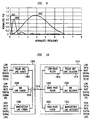
- FIG. 9 shows the normalized PSDs for the encoded signals in accordance with an embodiment of the invention in which a first low data rate digital signal at a data rate of R/4 is encoded using polar NRZ encoding, a second low data rate digital signal at a data rate of R is encoded using AMI encoding, and a third high data rate digital signal at a data rate of 4R is encoded using Manchester encoding.
- the PSD for the polar NRZ encoded signal is shown as curve 902
- the PSD for the AMI encoded signal is shown as curve 904
- the PSD for the Manchester encoded signal is shown as curve 906.
- the PSDs of the three encoded signals are substantially orthogonal in the frequency domain. All three signals have high PSD's in different frequency ranges. Further, in the frequency range in which one of the signals has a high PSD, the other signals have low PSD's. As a result, the three signals may be transmitted over the same physical medium with little or no interference.
- a transmitter 1002 receives a first low data rate (R/4) digital signal, a second low data rate (R) digital signal, and a third high data rate (4R) digital signal.
- the first low data rate digital signal is encoded by polar NRZ line coder 1004
- the second low data rate digital signal is encoded by AMI line coder 1006
- the third high data rate digital signal is encoded by Manchester line coder 1008.
- the three encoded signals are combined by combiner 1009 and transmitted via wire 1010 to receiver 1012.
- the signal is split and provided to a low-pass filter 1014, a band pass filter 1018, and a high-pass filter 1022.
- the low pass filter 1014, band pass filter 1018, and high pass filter 1022 are configured to pass the polar NRZ encoded signal, the AMI encoded signal, and the Manchester encoded signal respectively.
- the output of the low-pass filter 1014 is provided to a polar NRZ line decoder 1016 for decoding and the polar NRZ line decoder 1016 outputs the first low data rate digital signal.
- the output of the band pass filter 1018 is provided to an AMI line decoder 1020 for decoding and the AMI line decoder 1020 outputs the second low data rate digital signal.
- the output of the high pass filter 1022 is provided to a Manchester line decoder 1024 for decoding and the Manchester line decoder 1024 outputs the third high data rate digital signal.
- Figs. 6 and 10 are functional block diagrams of apparatuses in accordance with various embodiments of the invention. Given the figures and the description herein, one skilled in the art could readily implement the invention.
- the line coders and line decoders shown in Figs. 6 and 10 could be implemented using programmable processors in conjunction with appropriate software for performing the coding and decoding functions.
- the line coders and decoders could be implemented using hardware, or some combination of hardware and software.
Landscapes
- Engineering & Computer Science (AREA)
- Signal Processing (AREA)
- Computer Networks & Wireless Communication (AREA)
- Physics & Mathematics (AREA)
- Spectroscopy & Molecular Physics (AREA)
- Dc Digital Transmission (AREA)
- Transmission Systems Not Characterized By The Medium Used For Transmission (AREA)
Applications Claiming Priority (2)
| Application Number | Priority Date | Filing Date | Title |
|---|---|---|---|
| US363524 | 1999-07-29 | ||
| US09/363,524 US6456666B1 (en) | 1999-07-29 | 1999-07-29 | Signal encoding for transmission of multiple digital signals over single physical medium |
Publications (2)
| Publication Number | Publication Date |
|---|---|
| EP1073231A2 true EP1073231A2 (de) | 2001-01-31 |
| EP1073231A3 EP1073231A3 (de) | 2003-12-17 |
Family
ID=23430585
Family Applications (1)
| Application Number | Title | Priority Date | Filing Date |
|---|---|---|---|
| EP00306082A Withdrawn EP1073231A3 (de) | 1999-07-29 | 2000-07-17 | Signalkodierung zur Übertragung mehrerer digitalen Signale über ein einziges physikalisches Medium |
Country Status (4)
| Country | Link |
|---|---|
| US (2) | US6456666B1 (de) |
| EP (1) | EP1073231A3 (de) |
| JP (1) | JP2001069120A (de) |
| CA (1) | CA2314400C (de) |
Cited By (1)
| Publication number | Priority date | Publication date | Assignee | Title |
|---|---|---|---|---|
| EP2333998A2 (de) * | 2009-12-14 | 2011-06-15 | Samsung Electronics Co., Ltd. | Verfahren und Vorrichtung zur Übertragung dringender Daten |
Families Citing this family (4)
| Publication number | Priority date | Publication date | Assignee | Title |
|---|---|---|---|---|
| US8873592B1 (en) * | 2007-10-19 | 2014-10-28 | National Semiconductor Corporation | System and method for adding a low data rate data channel to a 100Base-T ethernet link |
| DE102010031317A1 (de) * | 2009-09-08 | 2011-04-28 | Electronics And Telecommunications Research Institute | Präambelerzeugungsvorrichtung und -verfahren für digitales Direktübertragungssystem |
| US9100047B2 (en) * | 2013-09-20 | 2015-08-04 | Intel Corporation | Method and apparatus for mitigating resonant effects within a power delivery network of a printed circuit board |
| US10135460B2 (en) | 2013-10-01 | 2018-11-20 | Texas Instruments Incorporated | Apparatus and method for multilevel coding (MLC) with binary alphabet polar codes |
Family Cites Families (15)
| Publication number | Priority date | Publication date | Assignee | Title |
|---|---|---|---|---|
| US3601544A (en) * | 1969-04-16 | 1971-08-24 | Sperry Rand Corp | Baseband frequency multiplexing scheme |
| US4425666A (en) * | 1982-01-29 | 1984-01-10 | Motorola Inc. | Data encoding and decoding communication system for three frequency FSK modulation and method therefor |
| US4524462A (en) | 1982-06-24 | 1985-06-18 | Italtel Societa Italiana Telecomunicazioni S.P.A. | System for jointly transmitting high-frequency and low-frequency digital signals over a fiber-optical carrier |
| DE3232599A1 (de) * | 1982-09-02 | 1984-03-08 | ANT Nachrichtentechnik GmbH, 7150 Backnang | System zur uebertragung digitaler signale |
| CH666150A5 (de) | 1984-09-28 | 1988-06-30 | Bbc Brown Boveri & Cie | Verfahren zur zusaetzlichen uebertragung von informationen ueber einen digitalen hilfskanal sowie anwendung des verfahrens. |
| GB2175480B (en) | 1985-05-21 | 1988-12-29 | Stc Plc | Demodulation of auxiliary low frequency channels in digital transmission systems |
| FR2630871B1 (fr) | 1988-04-29 | 1994-03-18 | Alcatel Cit | Procede et dispositif d'adjonction et de separation d'un canal numerique a bas debit au canal numerique a haut debit d'une liaison de transmission |
| JPH0746224A (ja) | 1992-10-09 | 1995-02-14 | Philips Electron Nv | 送信システム及び受信機 |
| US5633892A (en) | 1994-07-22 | 1997-05-27 | Alcatel Network Systems, Inc. | Hybrid line coding method and apparatus using 4B/3T encoding for payload bits and 1B/1T encoding for framing information |
| WO1996007260A1 (en) * | 1994-08-31 | 1996-03-07 | Sony Corporation | Signal transmitter, signal receiver, and signal transmitting-receiving method |
| JP4054391B2 (ja) * | 1995-12-28 | 2008-02-27 | キヤノン株式会社 | 映像復号化装置及び映像伝送システム |
| BR9612582A (pt) * | 1996-03-27 | 1999-07-20 | Bosch Gmbh Robert | Sistema de transmissão por rádio ponto-a-multiponto |
| US5914982A (en) * | 1997-06-13 | 1999-06-22 | Rockwell Semiconductor Systems, Inc. | Method and apparatus for training linear equalizers in a PCM modem |
| JPH11331305A (ja) * | 1998-05-08 | 1999-11-30 | Sony Corp | 送信装置および送信方法、受信装置および受信方法、並びに提供媒体 |
| US6404819B1 (en) * | 1998-11-20 | 2002-06-11 | Lucent Technologies Inc. | System and method for generating NRZ signals from RZ signals in communications networks |
-
1999
- 1999-07-29 US US09/363,524 patent/US6456666B1/en not_active Expired - Lifetime
-
2000
- 2000-07-17 EP EP00306082A patent/EP1073231A3/de not_active Withdrawn
- 2000-07-21 CA CA002314400A patent/CA2314400C/en not_active Expired - Fee Related
- 2000-07-27 JP JP2000226696A patent/JP2001069120A/ja active Pending
-
2002
- 2002-08-06 US US10/213,225 patent/US6721376B2/en not_active Expired - Lifetime
Non-Patent Citations (1)
| Title |
|---|
| None * |
Cited By (1)
| Publication number | Priority date | Publication date | Assignee | Title |
|---|---|---|---|---|
| EP2333998A2 (de) * | 2009-12-14 | 2011-06-15 | Samsung Electronics Co., Ltd. | Verfahren und Vorrichtung zur Übertragung dringender Daten |
Also Published As
| Publication number | Publication date |
|---|---|
| JP2001069120A (ja) | 2001-03-16 |
| CA2314400A1 (en) | 2001-01-29 |
| CA2314400C (en) | 2004-05-25 |
| US20020186792A1 (en) | 2002-12-12 |
| EP1073231A3 (de) | 2003-12-17 |
| US6721376B2 (en) | 2004-04-13 |
| US6456666B1 (en) | 2002-09-24 |
Similar Documents
| Publication | Publication Date | Title |
|---|---|---|
| US5119402A (en) | Method and apparatus for transmission of local area network signals over unshielded twisted pairs | |
| CA2330876C (en) | Methods and apparatus for verifying transmit power levels in a signal point limited transmission system | |
| US5856980A (en) | Baseband encoding method and apparatus for increasing the transmission rate over a communication medium | |
| EP0929958B1 (de) | Verfahren und system zur kompensation gestohlener bits zugeordnet zu einem empfänger oder codec | |
| FI82163B (fi) | Foerfarande att oeverfoera en extra informationskanal oever ett transmissionsmedium. | |
| CA2428529A1 (en) | Encoding method and system for reducing inter-symbol interference effects in transmission over a serial link | |
| US6463103B1 (en) | Frame-based sign inversion method and system for spectral shaping for pulse-coded-modulation modems | |
| US5796716A (en) | Method and apparatus for simultaneous voice/data transmission | |
| EP1330083B1 (de) | Digitaler datensender | |
| JPH02250528A (ja) | 連続データ伝送のための交流パルス反転符号化および復号化方式 | |
| US20030194017A1 (en) | Multilevel data encoding and modulation technique | |
| JPWO2002030075A1 (ja) | ディジタルデータ伝送装置、データ送信装置、データ受信装置、およびデータ送受信装置 | |
| US6721376B2 (en) | Signal encoding for transmission of multiple digital signals over single physical medium | |
| US5818879A (en) | Device, system and method for spectrally shaping transmitted data signals | |
| JPH04262650A (ja) | ブロックコードでコード化されたメインチャネルと付加チャネルとを有する伝送装置 | |
| US6404819B1 (en) | System and method for generating NRZ signals from RZ signals in communications networks | |
| KR100338911B1 (ko) | 송신용데이터신호처리장치및방법과,수신신호처리장치및방법 | |
| CA2285073A1 (en) | System and method for spectrally shaping transmitted data signals | |
| CA1213017A (en) | Method for transmitting digital signals | |
| US5737309A (en) | Method and apparatus for interface communications in a tandem cross connect | |
| KR100256699B1 (ko) | 스펙트럼 분할 다중 전송 장치 | |
| CA2267362A1 (en) | Device, system and method for spectrally shaping transmitted data signals | |
| Waters | Invited paper Line codes for metallic cable systems | |
| WO1998039883A1 (en) | Signalling method using multiple modulus conversion and shell mapping | |
| AU674851B2 (en) | Integrated services digital network complementary modem |
Legal Events
| Date | Code | Title | Description |
|---|---|---|---|
| PUAI | Public reference made under article 153(3) epc to a published international application that has entered the european phase |
Free format text: ORIGINAL CODE: 0009012 |
|
| AK | Designated contracting states |
Kind code of ref document: A2 Designated state(s): AT BE CH CY DE DK ES FI FR GB GR IE IT LI LU MC NL PT SE |
|
| AX | Request for extension of the european patent |
Free format text: AL;LT;LV;MK;RO;SI |
|
| PUAL | Search report despatched |
Free format text: ORIGINAL CODE: 0009013 |
|
| AK | Designated contracting states |
Kind code of ref document: A3 Designated state(s): AT BE CH CY DE DK ES FI FR GB GR IE IT LI LU MC NL PT SE |
|
| AX | Request for extension of the european patent |
Extension state: AL LT LV MK RO SI |
|
| 17P | Request for examination filed |
Effective date: 20040420 |
|
| 17Q | First examination report despatched |
Effective date: 20040526 |
|
| AKX | Designation fees paid |
Designated state(s): DE FR GB |
|
| STAA | Information on the status of an ep patent application or granted ep patent |
Free format text: STATUS: THE APPLICATION HAS BEEN WITHDRAWN |
|
| 18W | Application withdrawn |
Effective date: 20071019 |