EP1072463A1 - Current system for compensating the magnetic field produced by electric traction railways - Google Patents
Current system for compensating the magnetic field produced by electric traction railways Download PDFInfo
- Publication number
- EP1072463A1 EP1072463A1 EP00901614A EP00901614A EP1072463A1 EP 1072463 A1 EP1072463 A1 EP 1072463A1 EP 00901614 A EP00901614 A EP 00901614A EP 00901614 A EP00901614 A EP 00901614A EP 1072463 A1 EP1072463 A1 EP 1072463A1
- Authority
- EP
- European Patent Office
- Prior art keywords
- magnetic field
- catenary
- currents
- compensating
- return
- Prior art date
- Legal status (The legal status is an assumption and is not a legal conclusion. Google has not performed a legal analysis and makes no representation as to the accuracy of the status listed.)
- Withdrawn
Links
- 230000005291 magnetic effect Effects 0.000 title claims abstract description 35
- 239000004020 conductor Substances 0.000 claims abstract description 37
- 230000002349 favourable effect Effects 0.000 description 4
- 238000000034 method Methods 0.000 description 4
- 230000003094 perturbing effect Effects 0.000 description 3
- 239000007769 metal material Substances 0.000 description 2
- 230000009467 reduction Effects 0.000 description 2
- 238000005481 NMR spectroscopy Methods 0.000 description 1
- 238000010521 absorption reaction Methods 0.000 description 1
- 230000002238 attenuated effect Effects 0.000 description 1
- 238000006073 displacement reaction Methods 0.000 description 1
- 230000000694 effects Effects 0.000 description 1
- 230000005294 ferromagnetic effect Effects 0.000 description 1
- 230000003993 interaction Effects 0.000 description 1
- 238000005259 measurement Methods 0.000 description 1
Images


Classifications
-
- B—PERFORMING OPERATIONS; TRANSPORTING
- B60—VEHICLES IN GENERAL
- B60M—POWER SUPPLY LINES, AND DEVICES ALONG RAILS, FOR ELECTRICALLY- PROPELLED VEHICLES
- B60M1/00—Power supply lines for contact with collector on vehicle
- B60M1/02—Details
- B60M1/06—Arrangements along the power lines for reducing interference in nearby communication lines
Definitions
- the present invention relates to a device which can compensate, at origin, the magnetic field perturbations in the surroundings of the tracks of an electrically driven train caused by variations in the current of the power supply catenary.
- the method relies on shielding the magnetic field with a circuit of suitable geometry to compensate or reduce the field created by power lines of an electrical train.
- the method consists of reducing the magnetic field created by the variations in the power catenary current by rerouting the return currents in the tracks. This rerouting is achieved by conductors placed perpendicular to the track and is directed towards a conductor parallel to the catenary.
- fluctuations of the magnetic field caused y current fluctuations in the loop formed by the catenary and the return conductor may be compensated at origin regardless of the distance and orientation of the receiver of the perturbation with respect to the path of the train.
- the system is applied only to segments of the underground line which are near areas requiring shielding for diverse reasons.
- Shielding of the source of the perturbation such as shielding the train tunnel with a magnetic metallic material causes interactions with radiotelephony, capacitance problems and is extremely costly.
- the ideal method to eliminate perturbations would be to practically annul the area of the current loop by having a return current conductor near and parallel to the catenary, or equivalently a catenary power supply conductor placed between the tracks.
- the geometry or size of the loop originating the perturbation field are also variable and therefore cannot be compensated with a return conductor with a fixed geometry.
- the present invention instead of compensating at the source with active compensation loops uses the same catenary-train-track power supply current so that, through a return conductor parallel to and near the catenary, the loop causing the perturbations is eliminated. This is achieved by an electrical sectioning of the track in which perturbations must be eliminated and taking the return current to the catenary by vertical conductors placed symmetrically on the walls of the tunnel or on the catenary support columns in open air lines.
- the system of currents for compensating the magnetic field produced by electrically driven trains is based on reducing the effect of current fluctuations produced by power absorption and release of electric traction engines which generate a strong magnetic perturbation field in catenary powered trains where the track-engine-catenary-substation form a large surface current loop- All of this is achieved by a conductor located in the top area of the tunnel parallel to its section, which we shall term the return conductor. Only at areas where this is desired, the track shall be sectioned into successive electrically insulated conductor segments mutually insulated from each other, allowing to install as many return conductors as are required to obtain the displacement of the engine along the shielded area. The length of the sectioned segments is calculated and optimised considering the size of the engine and the geometrical conditions which provide the optimum results.
- the system of currents for compensating the magnetic field produced by electrically powered trains consists in creating a current to compensate the magnetic field produced which, according to figure 1, begins at substation (1), passes through catenary (4), reaches engine (2) and returns along tracks (5).
- figure 3 a shows the first case object of study. As we are here outside the shielded area and on the side of the substation (left) current returns in the normal manner and through the track.
- Figure 3B shows the return when still beyond the shielded area we are on the opposite side of the substation (right). In this case it is necessary to use the return conductors (6) as shown in the sketch.
- the current from the substation arrives, through the catenary, to the engine, from where it returns along the tracks until reaching the first vertical conductor, which shunts it to the horizontal return cable parallel to the catenary. In this manner it crosses the dangerous area and once it is crossed descends along a vertical conductor to the track finally reaching the substation.
- the dotted line shows the geometry of the current circuit.
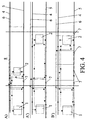
- Figure 4B shows the situation of 4A' but here with cuts made in the track. This allows to install as many vertical return conductors as desired. As the engine advances, it will use the one nearest to it. This allows to minimise the circuit area and to have a return current parallel to the catenary.
- the main objectives of the present invention may be considered as two: to reduce the area of the track-engine-catenary-substation circuit loop and, in the area to be shielded, to maintain a current in the conductor parallel to the catenary and in the opposite direction in order to achieve a cancellation of the magnetic field.
- the device is characterised by the attenuation factor s.
- This factor is defined as the quotient between the attenuated field and the initial field.
- a practical embodiment of the system claimed has been executed in a segment of underground line which due to its properties produced a perturbing magnetic field at floor level on the order of 15 ⁇ T.
- the return conductor (figure 4 A (6)) was suspended from the catenary (figure 4 A (4)) at a distance of 20 cm and the vertical conductors were placed as arcs, as shown in figure 5, on the walls and ceiling of the tunnel on track segments 18 m. long.
- the total length of the compensation area is 300 m.
- Measurements were made for different situations, from the most favourable to least favourable. Normal circulation of a single train, moving, stopping and starting again, moving, stopping on a slope and starting again. Circulation of two trains, one on each track, with starting orders given so that both trains coincide in motion in the special area. Allowing one train to circulate and the other stopping then starting in the danger area. Emergency braking and starting again, etc..
Landscapes
- Engineering & Computer Science (AREA)
- Mechanical Engineering (AREA)
- Shielding Devices Or Components To Electric Or Magnetic Fields (AREA)
- Current-Collector Devices For Electrically Propelled Vehicles (AREA)
- Train Traffic Observation, Control, And Security (AREA)
Abstract
The invention relates to a device that can compensate at the point of origin disturbances of the magnetic field in the surroundings of a
railway line caused by fluctuations in the current of the power supply catenary. Said system aims at creating a return circuit whose geometry
varies depending on the position of the train and which suppresses at the point of origin the field produced by the catenary-train-track and
reduces disturbances in the magnetic field in the surroundings. The system is based on deriving the return current from the track that is
divided into elementary segments isolated from one another to a return conductor located adjacent and parallel to the catenary by means of
a series of vertical conductors connecting each segment to the return conductor.
Description
- The present invention relates to a device which can compensate, at origin, the magnetic field perturbations in the surroundings of the tracks of an electrically driven train caused by variations in the current of the power supply catenary.
- The method relies on shielding the magnetic field with a circuit of suitable geometry to compensate or reduce the field created by power lines of an electrical train.
- The method consists of reducing the magnetic field created by the variations in the power catenary current by rerouting the return currents in the tracks. This rerouting is achieved by conductors placed perpendicular to the track and is directed towards a conductor parallel to the catenary. Thus, fluctuations of the magnetic field caused y current fluctuations in the loop formed by the catenary and the return conductor may be compensated at origin regardless of the distance and orientation of the receiver of the perturbation with respect to the path of the train.
- The system is applied only to segments of the underground line which are near areas requiring shielding for diverse reasons.
- Nowadays there are growing problems with electrical systems, computers, electron microscopes, nuclear magnetic resonance units, etc. due to perturbations of the Earth's magnetic field mainly caused by underground metropolitan trains which run nearby or under the sites in which these are installed. The problem is particularly serious for trains powered by a catenary line and current return on the tracks, and particularly when employing low voltage direct current (0, 6-3KV), and therefore high currents, on the order of 1-10 KA. In these cases the variable magnetic field created by current variations in the catenary-train-track loop reaches large values, on the order of the Earth's magnetic field at distances on the order of 100 metres from the train line.
- In certain cases magnetic shielding of the affected equipment has been proposed as a solution. On occasions it is simply the Earth's magnetic field that is shielded (WO9738534). This method suffers from disadvantages as it never obtains reductions above one tenth of the field which is shielded, and is expensive.
- Shielding of the source of the perturbation, such as shielding the train tunnel with a magnetic metallic material causes interactions with radiotelephony, capacitance problems and is extremely costly.
- The ideal method to eliminate perturbations would be to practically annul the area of the current loop by having a return current conductor near and parallel to the catenary, or equivalently a catenary power supply conductor placed between the tracks. However, as the train is moving and with it the point at which the catenary-train-track circuit is closed, the geometry or size of the loop originating the perturbation field are also variable and therefore cannot be compensated with a return conductor with a fixed geometry.
- Compensation at origin using return circuits has been performed by other authors (WO9633541) for high voltage lines. The difference between these systems and the one here considered is that, firstly, the field to be compensated is geometrically invariant over time, while the object of the present Patent is to shield a magnetic field which varies in a non-uniform manner. Other latter inventions (application P9802654) deal with the problem at the source of the perturbing field and instead of shielding with ferromagnetic metallic material use a compensation current loop controlled by magnetic field sensors.
- The present invention, instead of compensating at the source with active compensation loops uses the same catenary-train-track power supply current so that, through a return conductor parallel to and near the catenary, the loop causing the perturbations is eliminated. This is achieved by an electrical sectioning of the track in which perturbations must be eliminated and taking the return current to the catenary by vertical conductors placed symmetrically on the walls of the tunnel or on the catenary support columns in open air lines.
- The system of currents for compensating the magnetic field produced by electrically driven trains, object of the present invention, is based on reducing the effect of current fluctuations produced by power absorption and release of electric traction engines which generate a strong magnetic perturbation field in catenary powered trains where the track-engine-catenary-substation form a large surface current loop- All of this is achieved by a conductor located in the top area of the tunnel parallel to its section, which we shall term the return conductor. Only at areas where this is desired, the track shall be sectioned into successive electrically insulated conductor segments mutually insulated from each other, allowing to install as many return conductors as are required to obtain the displacement of the engine along the shielded area. The length of the sectioned segments is calculated and optimised considering the size of the engine and the geometrical conditions which provide the optimum results.
- Specifically, and with reference to the description of the figures, the system of currents for compensating the magnetic field produced by electrically powered trains consists in creating a current to compensate the magnetic field produced which, according to figure 1, begins at substation (1), passes through catenary (4), reaches engine (2) and returns along tracks (5). Likewise, and with reference to the figures, figure 3a shows the first case object of study. As we are here outside the shielded area and on the side of the substation (left) current returns in the normal manner and through the track. Figure 3B shows the return when still beyond the shielded area we are on the opposite side of the substation (right). In this case it is necessary to use the return conductors (6) as shown in the sketch. The current from the substation arrives, through the catenary, to the engine, from where it returns along the tracks until reaching the first vertical conductor, which shunts it to the horizontal return cable parallel to the catenary. In this manner it crosses the dangerous area and once it is crossed descends along a vertical conductor to the track finally reaching the substation. The dotted line shows the geometry of the current circuit. With this new geometry two objectives are obtained: reducing the are of the track-engine-catenary-substation circuit and obtaining, in the area object of the shielding, a compensation of the catenary current by the return current parallel to it.
- When entering a danger area (figure 4), on the side nearest the substation, the cut performed in the track allows to design a favourable return current (figure 4A). The current arriving from the substation reaches the engine, returns along the track along a short segment and just before reaching the cut rises along a return conductor to the horizontal one. Along the horizontal conductor it reaches another vertical conductor beyond the cut, along which it descends to reach the substation along the track. Thus, the surface area of the circuit is also reduced and in a small area a return current parallel to the catenary is obtained. Figure 4A' shows the appearance of the circuit if the engine moves away from the substation and the same return circuit is used. The lack of cuts in the tracks would force us to use the same vertical return conductor. In this case in addition to having a circuit with an enormous area there would not be a return current parallel to the catenary.
- Figure 4B shows the situation of 4A' but here with cuts made in the track. This allows to install as many vertical return conductors as desired. As the engine advances, it will use the one nearest to it. This allows to minimise the circuit area and to have a return current parallel to the catenary.
- It must be remarked that an circular arc-shaped current (6) leaves each rail (figure 5). In other words, what is represented in figures 3 and 4 as a vertical line is in fact the sum of two arc-shaped currents. The sum of these two currents is the total current. The current intensity is greater on that with the highest impedance. Note that this geometry is quite favourable as the composition of the magnetic fields created by each one is practically negligible. Figure 5 also shows the point of contact between the engine wheel and the track (9).
- The main objectives of the present invention may be considered as two: to reduce the area of the track-engine-catenary-substation circuit loop and, in the area to be shielded, to maintain a current in the conductor parallel to the catenary and in the opposite direction in order to achieve a cancellation of the magnetic field.
- The device is characterised by the attenuation factor s. This factor is defined as the quotient between the attenuated field and the initial field.
- The characteristics of the invention shall be more clearly understood in view of the accompanying drawings which form an integral part of the description, in which the following is shown:
- Figure 1 shows the current circuit (track-engine-catenary-substation) which causes the magnetic field. (1) is the substation, (2) is the engine, (4) the catenary, (5) are the racks, (3) is the tunnel. I is the current in the catenary and I1, I2 are the currents in the tracks.
- Figure 2. shows a sketch of the current circuit causing the magnetic field, as in figure 1.
It shows the mathematical expression
- Figure 3 shows a sketch of the shielding when the train is just ahead of (3A) and just after the area to be protected (3B). Where (4) is the catenary, (5) is the track, (6) are the return current conductors, (7) is the cut in the tracks and (8) is the area to be shielded.
- Figure 4. Shows the situation when the engine enters the dangerous area.
- Figure 4A shows the circuit between engine (2) and substation (1) suing return conductors (6); (4) is the catenary, (5) are the tracks, (7) are the cuts in the track.
- Figure 4A' shows the circuit if engine (2) were moving away from the substation and the same return circuit of figure 3A used.
- Figure 4B shows the situation of 4A' but here with cuts (7) provided in the track.
- Figure 5 shows a section of tunnel (3) showing the geometry of the vertical return current (6); (9) are the rails, (3) is the tunnel, (2) is the engine.
-
- The present invention is illustrated by the following example of a preferred embodiment of the same, made with reference to the figures.
- A practical embodiment of the system claimed has been executed in a segment of underground line which due to its properties produced a perturbing magnetic field at floor level on the order of 15 µT. The return conductor (figure 4 A (6)) was suspended from the catenary (figure 4 A (4)) at a distance of 20 cm and the vertical conductors were placed as arcs, as shown in figure 5, on the walls and ceiling of the tunnel on track segments 18 m. long. The total length of the compensation area is 300 m. With this a reduction of the perturbing field of up to 1.0 µT was obtained in the worst of cases. Measurements were made for different situations, from the most favourable to least favourable. Normal circulation of a single train, moving, stopping and starting again, moving, stopping on a slope and starting again. Circulation of two trains, one on each track, with starting orders given so that both trains coincide in motion in the special area. Allowing one train to circulate and the other stopping then starting in the danger area. Emergency braking and starting again, etc..
Claims (10)
- System of currents for compensating the magnetic field produced by electrically driven trains, characterised in that the return current for the power supply catenary is rerouted away from the tracks using alternative return conductors.
- System of currents for compensating the magnetic field produced by electrically driven trains, according to the previous claim, characterised in that one of the main power catenary current return cables is parallel and close to the catenary itself but carries current in the opposite direction to said catenary.
- System of currents for compensating the magnetic field produced by electrically driven trains, according to previous claim, by which the return conductors which reroute the current on the tracks to the return conductor of claim 1 are in a plane perpendicular to the plane of the tracks and parallel to the section of the tunnel.
- System of currents for compensating the magnetic field produced by electrically driven trains, as claimed in claim 3, in which the vertical return current comprises two circular arc-shaped conductors.
- System of currents for compensating the magnetic field produced by electrically driven trains, according to previous claims, characterised in that the sum of the currents in the return conductors of claim 2 is equal to that of the catenary.
- System of currents for compensating the magnetic field produced by electrically driven trains, according to previous claims, in which the track is provided with several cuts in order to electrically insulate each segment of a given length.
- System of currents for compensating the magnetic field produced by electrically driven trains, as claimed in claim 6, characterised in that the sections made in the track allow to install as many vertical return conductors as required to minimise the cross section of the substation-catenary-track-engine circuit.
- System of currents for compensating the magnetic field produced by electrically driven trains, as claimed in claim 6, by which the sections provided in the track allow to install as many vertical return conductors as required to obtain return currents parallel to the catenary with the required approximation.
- System of currents for compensating the magnetic field according to previous claims, in which in a manner symmetrical and fully equivalent to that described above, the catenary is cut into segments and current is taken to each segment by vertical conductors connected to a power line placed at track level.
- System of currents for compensating the magnetic field produced by electrically driven trains, according to previous claims, by which the fluctuations of the magnetic field caused by fluctuations in the catenary current are compensated at origin.
Applications Claiming Priority (5)
| Application Number | Priority Date | Filing Date | Title |
|---|---|---|---|
| ES9900237A ES2154210B1 (en) | 1999-02-04 | 1999-02-04 | COMPREHENSIVE CURRENT SYSTEM OF THE MAGNETIC FIELD PRODUCED PO R ELECTRICAL TRACTION RAILWAYS. |
| ES9900237 | 1999-02-04 | ||
| PCT/ES2000/000035 WO2000046064A1 (en) | 1999-02-04 | 2000-02-03 | Current system for compensating the magnetic field produced by electric traction railways |
| ES200000236 | 2000-02-03 | ||
| ES200000236A ES2158825B1 (en) | 1999-02-04 | 2000-02-03 | SYSTEM OF COMPENSATION CURRENTS OF THE MAGNETIC FIELD PRODUCED BY ELECTRIC TRACTION RAILWAYS. |
Publications (1)
| Publication Number | Publication Date |
|---|---|
| EP1072463A1 true EP1072463A1 (en) | 2001-01-31 |
Family
ID=26155206
Family Applications (1)
| Application Number | Title | Priority Date | Filing Date |
|---|---|---|---|
| EP00901614A Withdrawn EP1072463A1 (en) | 1999-02-04 | 2000-02-03 | Current system for compensating the magnetic field produced by electric traction railways |
Country Status (6)
| Country | Link |
|---|---|
| US (1) | US6492746B1 (en) |
| EP (1) | EP1072463A1 (en) |
| JP (1) | JP2002536227A (en) |
| AU (1) | AU2294900A (en) |
| CA (1) | CA2327180A1 (en) |
| WO (1) | WO2000046064A1 (en) |
Cited By (3)
| Publication number | Priority date | Publication date | Assignee | Title |
|---|---|---|---|---|
| EP1864848A1 (en) * | 2006-06-09 | 2007-12-12 | Technische Universiteit Delft | Compensation-device for a magnetic field |
| EP2017118A1 (en) | 2007-07-17 | 2009-01-21 | Technische Universiteit Delft | Railway infrastructure |
| NL1034189C2 (en) * | 2007-07-25 | 2009-01-27 | Em Power Systems | Building element for electrical supply of a rail vehicle, and electrical supply system comprising such a building element. |
Families Citing this family (7)
| Publication number | Priority date | Publication date | Assignee | Title |
|---|---|---|---|---|
| CA2327180A1 (en) | 1999-02-04 | 2000-08-10 | Universidad Complutense De Madrid | System of currents for compensating the magnetic field produced by electrically driven trains |
| US8693690B2 (en) | 2006-12-04 | 2014-04-08 | Red Hat, Inc. | Organizing an extensible table for storing cryptographic objects |
| DE102014107468A1 (en) * | 2014-05-27 | 2015-12-03 | Conductix-Wampfler Gmbh | Conductor line, pantograph and conductor rail system |
| ES2581127B2 (en) * | 2016-04-13 | 2017-05-04 | Universidad Complutense De Madrid | Label, system and method for long-distance object detection |
| CN106828199B (en) * | 2017-03-30 | 2023-03-17 | 北京全路通信信号研究设计院集团有限公司 | Cable anti-interference system for electrified railway section |
| CN108155595B (en) * | 2017-12-19 | 2024-07-12 | 国网浙江临海市供电有限公司 | Substation cable trench intelligent inspection system |
| CN112464603B (en) * | 2020-12-10 | 2024-05-24 | 广州市扬新技术研究有限责任公司 | Calculation method for traction current distribution in direct current traction network |
Family Cites Families (7)
| Publication number | Priority date | Publication date | Assignee | Title |
|---|---|---|---|---|
| DE2829578A1 (en) | 1978-07-05 | 1980-01-24 | Siemens Ag | Stray field compensation for railway track side control device - uses winding connected to points along current carrying line to counteract magnetic field |
| DE3410726A1 (en) | 1984-03-23 | 1985-09-26 | Brown, Boveri & Cie Ag, 6800 Mannheim | Single-phase metal-encapsulated alternating-current system |
| US5068543A (en) * | 1990-11-14 | 1991-11-26 | General Atomics | Low hazard extremely low frequency power transmission line |
| WO1995011541A1 (en) * | 1993-10-22 | 1995-04-27 | Norad Corporation | Apparatus and method for reducing electromagnetic fields near electrical power lines |
| US5616969A (en) * | 1995-07-11 | 1997-04-01 | Morava; Irena | Power distribution system having substantially zero electromagnetic field radiation |
| DE19642677A1 (en) | 1996-10-16 | 1998-04-23 | Abb Research Ltd | Three-phase overhead cable for electrical power transmission |
| CA2327180A1 (en) | 1999-02-04 | 2000-08-10 | Universidad Complutense De Madrid | System of currents for compensating the magnetic field produced by electrically driven trains |
-
2000
- 2000-02-03 CA CA002327180A patent/CA2327180A1/en not_active Abandoned
- 2000-02-03 US US09/647,724 patent/US6492746B1/en not_active Expired - Fee Related
- 2000-02-03 JP JP2000597153A patent/JP2002536227A/en active Pending
- 2000-02-03 EP EP00901614A patent/EP1072463A1/en not_active Withdrawn
- 2000-02-03 AU AU22949/00A patent/AU2294900A/en not_active Abandoned
- 2000-02-03 WO PCT/ES2000/000035 patent/WO2000046064A1/en not_active Ceased
Non-Patent Citations (1)
| Title |
|---|
| See references of WO0046064A1 * |
Cited By (4)
| Publication number | Priority date | Publication date | Assignee | Title |
|---|---|---|---|---|
| EP1864848A1 (en) * | 2006-06-09 | 2007-12-12 | Technische Universiteit Delft | Compensation-device for a magnetic field |
| EP2017118A1 (en) | 2007-07-17 | 2009-01-21 | Technische Universiteit Delft | Railway infrastructure |
| NL1034189C2 (en) * | 2007-07-25 | 2009-01-27 | Em Power Systems | Building element for electrical supply of a rail vehicle, and electrical supply system comprising such a building element. |
| WO2009014426A1 (en) * | 2007-07-25 | 2009-01-29 | Em Power Systems B.V. | Construction element for supllying electrical power to a rail vehicle and electrical power supply system comprising such a construction element |
Also Published As
| Publication number | Publication date |
|---|---|
| JP2002536227A (en) | 2002-10-29 |
| AU2294900A (en) | 2000-08-25 |
| CA2327180A1 (en) | 2000-08-10 |
| WO2000046064A1 (en) | 2000-08-10 |
| US6492746B1 (en) | 2002-12-10 |
Similar Documents
| Publication | Publication Date | Title |
|---|---|---|
| EP3421289B1 (en) | Railway transportation power supply construction | |
| US6492746B1 (en) | Current system for compensating the magnetic field produced by electric traction railways | |
| AU2004247331B2 (en) | Transport system | |
| KR20120036274A (en) | Ground-based power supply system for a transportation vehicle and associated methods | |
| Oancea et al. | On the electromagnetic field in the surrounding area of railway equipment and installations | |
| CN105358361A (en) | Conductor line, current collector, and conductor line system with a slotted waveguide for receiving an antenna | |
| US3869990A (en) | Switch arrangement for a magnetic suspension railroad | |
| Milesevic et al. | Electromagnetic fields and induced voltages on underground pipeline in the vicinity of ac traction system | |
| JP2011172420A (en) | Current collector for railroad car | |
| JPH0840116A (en) | Railway DC feeding system | |
| CN101736659A (en) | Method for installing track of automated people mover | |
| Tortia | Turin-Milan high-speed railway-line, 2x25 kV 50 Hz AC electrified. EMC problems in earthing of exposed conductive parts | |
| US514972A (en) | Electric—Railway System | |
| US3339031A (en) | Metal protected voltage conductor for rapid transit electrification | |
| Slemon et al. | A linear synchronous motor for urban transit using rare-earth magnets | |
| JPS61278435A (en) | Direct current feeding system for tramcar | |
| EP2017118B1 (en) | Railway infrastructure | |
| JPS58194631A (en) | Direct current feeding system for tramcar | |
| Tierney et al. | Improvement to the booster transformer/return conductor method of suppressing 50 Hz interference from ac-electrified railway systems | |
| Ogunsola | Analysis of EM coupling from AC electrified railway to nearby earth return circuit | |
| WO2009014426A1 (en) | Construction element for supllying electrical power to a rail vehicle and electrical power supply system comprising such a construction element | |
| JPH0142852B2 (en) | ||
| JPS5963231A (en) | Direct current feeding system for electric car | |
| WO2000037280A1 (en) | Device for compensating the magnetic field produced by electric traction railways | |
| JPS60234034A (en) | Electrically sectioning device for catenary suspension |
Legal Events
| Date | Code | Title | Description |
|---|---|---|---|
| PUAI | Public reference made under article 153(3) epc to a published international application that has entered the european phase |
Free format text: ORIGINAL CODE: 0009012 |
|
| 17P | Request for examination filed |
Effective date: 20001030 |
|
| AK | Designated contracting states |
Kind code of ref document: A1 Designated state(s): AT BE CH CY DE DK ES FI FR GB GR IE IT LI LU MC NL PT SE |
|
| RBV | Designated contracting states (corrected) |
Designated state(s): AT BE CH CY DE DK FI FR GB GR IE IT LI LU MC NL PT SE |
|
| STAA | Information on the status of an ep patent application or granted ep patent |
Free format text: STATUS: THE APPLICATION IS DEEMED TO BE WITHDRAWN |
|
| 18D | Application deemed to be withdrawn |
Effective date: 20040901 |