EP1072396A2 - Sandwich structure and method of repairing the same - Google Patents
Sandwich structure and method of repairing the same Download PDFInfo
- Publication number
- EP1072396A2 EP1072396A2 EP00116536A EP00116536A EP1072396A2 EP 1072396 A2 EP1072396 A2 EP 1072396A2 EP 00116536 A EP00116536 A EP 00116536A EP 00116536 A EP00116536 A EP 00116536A EP 1072396 A2 EP1072396 A2 EP 1072396A2
- Authority
- EP
- European Patent Office
- Prior art keywords
- core
- surface plate
- sandwich structure
- plate
- opening
- Prior art date
- Legal status (The legal status is an assumption and is not a legal conclusion. Google has not performed a legal analysis and makes no representation as to the accuracy of the status listed.)
- Granted
Links
Images


Classifications
-
- B—PERFORMING OPERATIONS; TRANSPORTING
- B29—WORKING OF PLASTICS; WORKING OF SUBSTANCES IN A PLASTIC STATE IN GENERAL
- B29C—SHAPING OR JOINING OF PLASTICS; SHAPING OF MATERIAL IN A PLASTIC STATE, NOT OTHERWISE PROVIDED FOR; AFTER-TREATMENT OF THE SHAPED PRODUCTS, e.g. REPAIRING
- B29C73/00—Repairing of articles made from plastics or substances in a plastic state, e.g. of articles shaped or produced by using techniques covered by this subclass or subclass B29D
- B29C73/04—Repairing of articles made from plastics or substances in a plastic state, e.g. of articles shaped or produced by using techniques covered by this subclass or subclass B29D using preformed elements
-
- B—PERFORMING OPERATIONS; TRANSPORTING
- B32—LAYERED PRODUCTS
- B32B—LAYERED PRODUCTS, i.e. PRODUCTS BUILT-UP OF STRATA OF FLAT OR NON-FLAT, e.g. CELLULAR OR HONEYCOMB, FORM
- B32B27/00—Layered products comprising a layer of synthetic resin
- B32B27/06—Layered products comprising a layer of synthetic resin as the main or only constituent of a layer, which is next to another layer of the same or of a different material
- B32B27/065—Layered products comprising a layer of synthetic resin as the main or only constituent of a layer, which is next to another layer of the same or of a different material of foam
-
- B—PERFORMING OPERATIONS; TRANSPORTING
- B29—WORKING OF PLASTICS; WORKING OF SUBSTANCES IN A PLASTIC STATE IN GENERAL
- B29C—SHAPING OR JOINING OF PLASTICS; SHAPING OF MATERIAL IN A PLASTIC STATE, NOT OTHERWISE PROVIDED FOR; AFTER-TREATMENT OF THE SHAPED PRODUCTS, e.g. REPAIRING
- B29C73/00—Repairing of articles made from plastics or substances in a plastic state, e.g. of articles shaped or produced by using techniques covered by this subclass or subclass B29D
- B29C73/24—Apparatus or accessories not otherwise provided for
- B29C73/26—Apparatus or accessories not otherwise provided for for mechanical pretreatment
-
- B—PERFORMING OPERATIONS; TRANSPORTING
- B32—LAYERED PRODUCTS
- B32B—LAYERED PRODUCTS, i.e. PRODUCTS BUILT-UP OF STRATA OF FLAT OR NON-FLAT, e.g. CELLULAR OR HONEYCOMB, FORM
- B32B3/00—Layered products comprising a layer with external or internal discontinuities or unevennesses, or a layer of non-planar shape; Layered products comprising a layer having particular features of form
- B32B3/02—Layered products comprising a layer with external or internal discontinuities or unevennesses, or a layer of non-planar shape; Layered products comprising a layer having particular features of form characterised by features of form at particular places, e.g. in edge regions
-
- B—PERFORMING OPERATIONS; TRANSPORTING
- B32—LAYERED PRODUCTS
- B32B—LAYERED PRODUCTS, i.e. PRODUCTS BUILT-UP OF STRATA OF FLAT OR NON-FLAT, e.g. CELLULAR OR HONEYCOMB, FORM
- B32B3/00—Layered products comprising a layer with external or internal discontinuities or unevennesses, or a layer of non-planar shape; Layered products comprising a layer having particular features of form
- B32B3/10—Layered products comprising a layer with external or internal discontinuities or unevennesses, or a layer of non-planar shape; Layered products comprising a layer having particular features of form characterised by a discontinuous layer, i.e. formed of separate pieces of material
- B32B3/12—Layered products comprising a layer with external or internal discontinuities or unevennesses, or a layer of non-planar shape; Layered products comprising a layer having particular features of form characterised by a discontinuous layer, i.e. formed of separate pieces of material characterised by a layer of regularly- arranged cells, e.g. a honeycomb structure
-
- B—PERFORMING OPERATIONS; TRANSPORTING
- B32—LAYERED PRODUCTS
- B32B—LAYERED PRODUCTS, i.e. PRODUCTS BUILT-UP OF STRATA OF FLAT OR NON-FLAT, e.g. CELLULAR OR HONEYCOMB, FORM
- B32B5/00—Layered products characterised by the non- homogeneity or physical structure, i.e. comprising a fibrous, filamentary, particulate or foam layer; Layered products characterised by having a layer differing constitutionally or physically in different parts
- B32B5/18—Layered products characterised by the non- homogeneity or physical structure, i.e. comprising a fibrous, filamentary, particulate or foam layer; Layered products characterised by having a layer differing constitutionally or physically in different parts characterised by features of a layer of foamed material
-
- B—PERFORMING OPERATIONS; TRANSPORTING
- B32—LAYERED PRODUCTS
- B32B—LAYERED PRODUCTS, i.e. PRODUCTS BUILT-UP OF STRATA OF FLAT OR NON-FLAT, e.g. CELLULAR OR HONEYCOMB, FORM
- B32B5/00—Layered products characterised by the non- homogeneity or physical structure, i.e. comprising a fibrous, filamentary, particulate or foam layer; Layered products characterised by having a layer differing constitutionally or physically in different parts
- B32B5/22—Layered products characterised by the non- homogeneity or physical structure, i.e. comprising a fibrous, filamentary, particulate or foam layer; Layered products characterised by having a layer differing constitutionally or physically in different parts characterised by the presence of two or more layers which are next to each other and are fibrous, filamentary, formed of particles or foamed
- B32B5/24—Layered products characterised by the non- homogeneity or physical structure, i.e. comprising a fibrous, filamentary, particulate or foam layer; Layered products characterised by having a layer differing constitutionally or physically in different parts characterised by the presence of two or more layers which are next to each other and are fibrous, filamentary, formed of particles or foamed one layer being a fibrous or filamentary layer
- B32B5/26—Layered products characterised by the non- homogeneity or physical structure, i.e. comprising a fibrous, filamentary, particulate or foam layer; Layered products characterised by having a layer differing constitutionally or physically in different parts characterised by the presence of two or more layers which are next to each other and are fibrous, filamentary, formed of particles or foamed one layer being a fibrous or filamentary layer another layer next to it also being fibrous or filamentary
-
- B—PERFORMING OPERATIONS; TRANSPORTING
- B29—WORKING OF PLASTICS; WORKING OF SUBSTANCES IN A PLASTIC STATE IN GENERAL
- B29C—SHAPING OR JOINING OF PLASTICS; SHAPING OF MATERIAL IN A PLASTIC STATE, NOT OTHERWISE PROVIDED FOR; AFTER-TREATMENT OF THE SHAPED PRODUCTS, e.g. REPAIRING
- B29C73/00—Repairing of articles made from plastics or substances in a plastic state, e.g. of articles shaped or produced by using techniques covered by this subclass or subclass B29D
- B29C73/24—Apparatus or accessories not otherwise provided for
- B29C73/26—Apparatus or accessories not otherwise provided for for mechanical pretreatment
- B29C2073/266—Apparatus or accessories not otherwise provided for for mechanical pretreatment for cutting out an undercut for anchoring the repairing material
-
- B—PERFORMING OPERATIONS; TRANSPORTING
- B29—WORKING OF PLASTICS; WORKING OF SUBSTANCES IN A PLASTIC STATE IN GENERAL
- B29C—SHAPING OR JOINING OF PLASTICS; SHAPING OF MATERIAL IN A PLASTIC STATE, NOT OTHERWISE PROVIDED FOR; AFTER-TREATMENT OF THE SHAPED PRODUCTS, e.g. REPAIRING
- B29C73/00—Repairing of articles made from plastics or substances in a plastic state, e.g. of articles shaped or produced by using techniques covered by this subclass or subclass B29D
- B29C73/24—Apparatus or accessories not otherwise provided for
- B29C73/26—Apparatus or accessories not otherwise provided for for mechanical pretreatment
- B29C2073/268—Apparatus or accessories not otherwise provided for for mechanical pretreatment for drilling holes in the area to be repaired
-
- B—PERFORMING OPERATIONS; TRANSPORTING
- B29—WORKING OF PLASTICS; WORKING OF SUBSTANCES IN A PLASTIC STATE IN GENERAL
- B29K—INDEXING SCHEME ASSOCIATED WITH SUBCLASSES B29B, B29C OR B29D, RELATING TO MOULDING MATERIALS OR TO MATERIALS FOR MOULDS, REINFORCEMENTS, FILLERS OR PREFORMED PARTS, e.g. INSERTS
- B29K2105/00—Condition, form or state of moulded material or of the material to be shaped
- B29K2105/04—Condition, form or state of moulded material or of the material to be shaped cellular or porous
- B29K2105/046—Condition, form or state of moulded material or of the material to be shaped cellular or porous with closed cells
-
- B—PERFORMING OPERATIONS; TRANSPORTING
- B29—WORKING OF PLASTICS; WORKING OF SUBSTANCES IN A PLASTIC STATE IN GENERAL
- B29L—INDEXING SCHEME ASSOCIATED WITH SUBCLASS B29C, RELATING TO PARTICULAR ARTICLES
- B29L2007/00—Flat articles, e.g. films or sheets
- B29L2007/002—Panels; Plates; Sheets
-
- B—PERFORMING OPERATIONS; TRANSPORTING
- B29—WORKING OF PLASTICS; WORKING OF SUBSTANCES IN A PLASTIC STATE IN GENERAL
- B29L—INDEXING SCHEME ASSOCIATED WITH SUBCLASS B29C, RELATING TO PARTICULAR ARTICLES
- B29L2009/00—Layered products
-
- B—PERFORMING OPERATIONS; TRANSPORTING
- B32—LAYERED PRODUCTS
- B32B—LAYERED PRODUCTS, i.e. PRODUCTS BUILT-UP OF STRATA OF FLAT OR NON-FLAT, e.g. CELLULAR OR HONEYCOMB, FORM
- B32B2266/00—Composition of foam
- B32B2266/08—Closed cell foam
-
- B—PERFORMING OPERATIONS; TRANSPORTING
- B32—LAYERED PRODUCTS
- B32B—LAYERED PRODUCTS, i.e. PRODUCTS BUILT-UP OF STRATA OF FLAT OR NON-FLAT, e.g. CELLULAR OR HONEYCOMB, FORM
- B32B2605/00—Vehicles
- B32B2605/08—Cars
-
- B—PERFORMING OPERATIONS; TRANSPORTING
- B32—LAYERED PRODUCTS
- B32B—LAYERED PRODUCTS, i.e. PRODUCTS BUILT-UP OF STRATA OF FLAT OR NON-FLAT, e.g. CELLULAR OR HONEYCOMB, FORM
- B32B2605/00—Vehicles
- B32B2605/12—Ships
-
- B—PERFORMING OPERATIONS; TRANSPORTING
- B32—LAYERED PRODUCTS
- B32B—LAYERED PRODUCTS, i.e. PRODUCTS BUILT-UP OF STRATA OF FLAT OR NON-FLAT, e.g. CELLULAR OR HONEYCOMB, FORM
- B32B2605/00—Vehicles
- B32B2605/18—Aircraft
-
- Y—GENERAL TAGGING OF NEW TECHNOLOGICAL DEVELOPMENTS; GENERAL TAGGING OF CROSS-SECTIONAL TECHNOLOGIES SPANNING OVER SEVERAL SECTIONS OF THE IPC; TECHNICAL SUBJECTS COVERED BY FORMER USPC CROSS-REFERENCE ART COLLECTIONS [XRACs] AND DIGESTS
- Y10—TECHNICAL SUBJECTS COVERED BY FORMER USPC
- Y10T—TECHNICAL SUBJECTS COVERED BY FORMER US CLASSIFICATION
- Y10T29/00—Metal working
- Y10T29/49—Method of mechanical manufacture
- Y10T29/49616—Structural member making
- Y10T29/49618—Restoring existing member, e.g., reinforcing, repairing
-
- Y—GENERAL TAGGING OF NEW TECHNOLOGICAL DEVELOPMENTS; GENERAL TAGGING OF CROSS-SECTIONAL TECHNOLOGIES SPANNING OVER SEVERAL SECTIONS OF THE IPC; TECHNICAL SUBJECTS COVERED BY FORMER USPC CROSS-REFERENCE ART COLLECTIONS [XRACs] AND DIGESTS
- Y10—TECHNICAL SUBJECTS COVERED BY FORMER USPC
- Y10T—TECHNICAL SUBJECTS COVERED BY FORMER US CLASSIFICATION
- Y10T29/00—Metal working
- Y10T29/49—Method of mechanical manufacture
- Y10T29/49616—Structural member making
- Y10T29/49622—Vehicular structural member making
-
- Y—GENERAL TAGGING OF NEW TECHNOLOGICAL DEVELOPMENTS; GENERAL TAGGING OF CROSS-SECTIONAL TECHNOLOGIES SPANNING OVER SEVERAL SECTIONS OF THE IPC; TECHNICAL SUBJECTS COVERED BY FORMER USPC CROSS-REFERENCE ART COLLECTIONS [XRACs] AND DIGESTS
- Y10—TECHNICAL SUBJECTS COVERED BY FORMER USPC
- Y10T—TECHNICAL SUBJECTS COVERED BY FORMER US CLASSIFICATION
- Y10T29/00—Metal working
- Y10T29/49—Method of mechanical manufacture
- Y10T29/49616—Structural member making
- Y10T29/49623—Static structure, e.g., a building component
- Y10T29/49629—Panel
-
- Y—GENERAL TAGGING OF NEW TECHNOLOGICAL DEVELOPMENTS; GENERAL TAGGING OF CROSS-SECTIONAL TECHNOLOGIES SPANNING OVER SEVERAL SECTIONS OF THE IPC; TECHNICAL SUBJECTS COVERED BY FORMER USPC CROSS-REFERENCE ART COLLECTIONS [XRACs] AND DIGESTS
- Y10—TECHNICAL SUBJECTS COVERED BY FORMER USPC
- Y10T—TECHNICAL SUBJECTS COVERED BY FORMER US CLASSIFICATION
- Y10T29/00—Metal working
- Y10T29/49—Method of mechanical manufacture
- Y10T29/49718—Repairing
- Y10T29/49732—Repairing by attaching repair preform, e.g., remaking, restoring, or patching
- Y10T29/49734—Repairing by attaching repair preform, e.g., remaking, restoring, or patching and removing damaged material
- Y10T29/49735—Mechanically attaching preform with separate fastener
-
- Y—GENERAL TAGGING OF NEW TECHNOLOGICAL DEVELOPMENTS; GENERAL TAGGING OF CROSS-SECTIONAL TECHNOLOGIES SPANNING OVER SEVERAL SECTIONS OF THE IPC; TECHNICAL SUBJECTS COVERED BY FORMER USPC CROSS-REFERENCE ART COLLECTIONS [XRACs] AND DIGESTS
- Y10—TECHNICAL SUBJECTS COVERED BY FORMER USPC
- Y10T—TECHNICAL SUBJECTS COVERED BY FORMER US CLASSIFICATION
- Y10T29/00—Metal working
- Y10T29/49—Method of mechanical manufacture
- Y10T29/49718—Repairing
- Y10T29/49732—Repairing by attaching repair preform, e.g., remaking, restoring, or patching
- Y10T29/49739—Mechanically attaching preform by separate fastener
-
- Y—GENERAL TAGGING OF NEW TECHNOLOGICAL DEVELOPMENTS; GENERAL TAGGING OF CROSS-SECTIONAL TECHNOLOGIES SPANNING OVER SEVERAL SECTIONS OF THE IPC; TECHNICAL SUBJECTS COVERED BY FORMER USPC CROSS-REFERENCE ART COLLECTIONS [XRACs] AND DIGESTS
- Y10—TECHNICAL SUBJECTS COVERED BY FORMER USPC
- Y10T—TECHNICAL SUBJECTS COVERED BY FORMER US CLASSIFICATION
- Y10T29/00—Metal working
- Y10T29/49—Method of mechanical manufacture
- Y10T29/49826—Assembling or joining
- Y10T29/49908—Joining by deforming
-
- Y—GENERAL TAGGING OF NEW TECHNOLOGICAL DEVELOPMENTS; GENERAL TAGGING OF CROSS-SECTIONAL TECHNOLOGIES SPANNING OVER SEVERAL SECTIONS OF THE IPC; TECHNICAL SUBJECTS COVERED BY FORMER USPC CROSS-REFERENCE ART COLLECTIONS [XRACs] AND DIGESTS
- Y10—TECHNICAL SUBJECTS COVERED BY FORMER USPC
- Y10T—TECHNICAL SUBJECTS COVERED BY FORMER US CLASSIFICATION
- Y10T29/00—Metal working
- Y10T29/49—Method of mechanical manufacture
- Y10T29/49826—Assembling or joining
- Y10T29/49947—Assembling or joining by applying separate fastener
- Y10T29/49954—Fastener deformed after application
- Y10T29/49956—Riveting
- Y10T29/49957—At least one part nonmetallic
-
- Y—GENERAL TAGGING OF NEW TECHNOLOGICAL DEVELOPMENTS; GENERAL TAGGING OF CROSS-SECTIONAL TECHNOLOGIES SPANNING OVER SEVERAL SECTIONS OF THE IPC; TECHNICAL SUBJECTS COVERED BY FORMER USPC CROSS-REFERENCE ART COLLECTIONS [XRACs] AND DIGESTS
- Y10—TECHNICAL SUBJECTS COVERED BY FORMER USPC
- Y10T—TECHNICAL SUBJECTS COVERED BY FORMER US CLASSIFICATION
- Y10T428/00—Stock material or miscellaneous articles
- Y10T428/23—Sheet including cover or casing
- Y10T428/233—Foamed or expanded material encased
-
- Y—GENERAL TAGGING OF NEW TECHNOLOGICAL DEVELOPMENTS; GENERAL TAGGING OF CROSS-SECTIONAL TECHNOLOGIES SPANNING OVER SEVERAL SECTIONS OF THE IPC; TECHNICAL SUBJECTS COVERED BY FORMER USPC CROSS-REFERENCE ART COLLECTIONS [XRACs] AND DIGESTS
- Y10—TECHNICAL SUBJECTS COVERED BY FORMER USPC
- Y10T—TECHNICAL SUBJECTS COVERED BY FORMER US CLASSIFICATION
- Y10T428/00—Stock material or miscellaneous articles
- Y10T428/23—Sheet including cover or casing
- Y10T428/234—Sheet including cover or casing including elements cooperating to form cells
- Y10T428/236—Honeycomb type cells extend perpendicularly to nonthickness layer
-
- Y—GENERAL TAGGING OF NEW TECHNOLOGICAL DEVELOPMENTS; GENERAL TAGGING OF CROSS-SECTIONAL TECHNOLOGIES SPANNING OVER SEVERAL SECTIONS OF THE IPC; TECHNICAL SUBJECTS COVERED BY FORMER USPC CROSS-REFERENCE ART COLLECTIONS [XRACs] AND DIGESTS
- Y10—TECHNICAL SUBJECTS COVERED BY FORMER USPC
- Y10T—TECHNICAL SUBJECTS COVERED BY FORMER US CLASSIFICATION
- Y10T428/00—Stock material or miscellaneous articles
- Y10T428/24—Structurally defined web or sheet [e.g., overall dimension, etc.]
- Y10T428/24149—Honeycomb-like
- Y10T428/24157—Filled honeycomb cells [e.g., solid substance in cavities, etc.]
-
- Y—GENERAL TAGGING OF NEW TECHNOLOGICAL DEVELOPMENTS; GENERAL TAGGING OF CROSS-SECTIONAL TECHNOLOGIES SPANNING OVER SEVERAL SECTIONS OF THE IPC; TECHNICAL SUBJECTS COVERED BY FORMER USPC CROSS-REFERENCE ART COLLECTIONS [XRACs] AND DIGESTS
- Y10—TECHNICAL SUBJECTS COVERED BY FORMER USPC
- Y10T—TECHNICAL SUBJECTS COVERED BY FORMER US CLASSIFICATION
- Y10T428/00—Stock material or miscellaneous articles
- Y10T428/24—Structurally defined web or sheet [e.g., overall dimension, etc.]
- Y10T428/24149—Honeycomb-like
- Y10T428/24165—Hexagonally shaped cavities
-
- Y—GENERAL TAGGING OF NEW TECHNOLOGICAL DEVELOPMENTS; GENERAL TAGGING OF CROSS-SECTIONAL TECHNOLOGIES SPANNING OVER SEVERAL SECTIONS OF THE IPC; TECHNICAL SUBJECTS COVERED BY FORMER USPC CROSS-REFERENCE ART COLLECTIONS [XRACs] AND DIGESTS
- Y10—TECHNICAL SUBJECTS COVERED BY FORMER USPC
- Y10T—TECHNICAL SUBJECTS COVERED BY FORMER US CLASSIFICATION
- Y10T428/00—Stock material or miscellaneous articles
- Y10T428/24—Structurally defined web or sheet [e.g., overall dimension, etc.]
- Y10T428/24479—Structurally defined web or sheet [e.g., overall dimension, etc.] including variation in thickness
- Y10T428/24496—Foamed or cellular component
- Y10T428/24504—Component comprises a polymer [e.g., rubber, etc.]
- Y10T428/24512—Polyurethane
-
- Y—GENERAL TAGGING OF NEW TECHNOLOGICAL DEVELOPMENTS; GENERAL TAGGING OF CROSS-SECTIONAL TECHNOLOGIES SPANNING OVER SEVERAL SECTIONS OF THE IPC; TECHNICAL SUBJECTS COVERED BY FORMER USPC CROSS-REFERENCE ART COLLECTIONS [XRACs] AND DIGESTS
- Y10—TECHNICAL SUBJECTS COVERED BY FORMER USPC
- Y10T—TECHNICAL SUBJECTS COVERED BY FORMER US CLASSIFICATION
- Y10T428/00—Stock material or miscellaneous articles
- Y10T428/24—Structurally defined web or sheet [e.g., overall dimension, etc.]
- Y10T428/24479—Structurally defined web or sheet [e.g., overall dimension, etc.] including variation in thickness
- Y10T428/24521—Structurally defined web or sheet [e.g., overall dimension, etc.] including variation in thickness with component conforming to contour of nonplanar surface
-
- Y—GENERAL TAGGING OF NEW TECHNOLOGICAL DEVELOPMENTS; GENERAL TAGGING OF CROSS-SECTIONAL TECHNOLOGIES SPANNING OVER SEVERAL SECTIONS OF THE IPC; TECHNICAL SUBJECTS COVERED BY FORMER USPC CROSS-REFERENCE ART COLLECTIONS [XRACs] AND DIGESTS
- Y10—TECHNICAL SUBJECTS COVERED BY FORMER USPC
- Y10T—TECHNICAL SUBJECTS COVERED BY FORMER US CLASSIFICATION
- Y10T428/00—Stock material or miscellaneous articles
- Y10T428/249921—Web or sheet containing structurally defined element or component
- Y10T428/249923—Including interlaminar mechanical fastener
-
- Y—GENERAL TAGGING OF NEW TECHNOLOGICAL DEVELOPMENTS; GENERAL TAGGING OF CROSS-SECTIONAL TECHNOLOGIES SPANNING OVER SEVERAL SECTIONS OF THE IPC; TECHNICAL SUBJECTS COVERED BY FORMER USPC CROSS-REFERENCE ART COLLECTIONS [XRACs] AND DIGESTS
- Y10—TECHNICAL SUBJECTS COVERED BY FORMER USPC
- Y10T—TECHNICAL SUBJECTS COVERED BY FORMER US CLASSIFICATION
- Y10T428/00—Stock material or miscellaneous articles
- Y10T428/249921—Web or sheet containing structurally defined element or component
- Y10T428/249924—Noninterengaged fiber-containing paper-free web or sheet which is not of specified porosity
- Y10T428/24994—Fiber embedded in or on the surface of a polymeric matrix
-
- Y—GENERAL TAGGING OF NEW TECHNOLOGICAL DEVELOPMENTS; GENERAL TAGGING OF CROSS-SECTIONAL TECHNOLOGIES SPANNING OVER SEVERAL SECTIONS OF THE IPC; TECHNICAL SUBJECTS COVERED BY FORMER USPC CROSS-REFERENCE ART COLLECTIONS [XRACs] AND DIGESTS
- Y10—TECHNICAL SUBJECTS COVERED BY FORMER USPC
- Y10T—TECHNICAL SUBJECTS COVERED BY FORMER US CLASSIFICATION
- Y10T428/00—Stock material or miscellaneous articles
- Y10T428/249921—Web or sheet containing structurally defined element or component
- Y10T428/249953—Composite having voids in a component [e.g., porous, cellular, etc.]
- Y10T428/24996—With internal element bridging layers, nonplanar interface between layers, or intermediate layer of commingled adjacent foam layers
-
- Y—GENERAL TAGGING OF NEW TECHNOLOGICAL DEVELOPMENTS; GENERAL TAGGING OF CROSS-SECTIONAL TECHNOLOGIES SPANNING OVER SEVERAL SECTIONS OF THE IPC; TECHNICAL SUBJECTS COVERED BY FORMER USPC CROSS-REFERENCE ART COLLECTIONS [XRACs] AND DIGESTS
- Y10—TECHNICAL SUBJECTS COVERED BY FORMER USPC
- Y10T—TECHNICAL SUBJECTS COVERED BY FORMER US CLASSIFICATION
- Y10T428/00—Stock material or miscellaneous articles
- Y10T428/249921—Web or sheet containing structurally defined element or component
- Y10T428/249953—Composite having voids in a component [e.g., porous, cellular, etc.]
- Y10T428/249976—Voids specified as closed
-
- Y—GENERAL TAGGING OF NEW TECHNOLOGICAL DEVELOPMENTS; GENERAL TAGGING OF CROSS-SECTIONAL TECHNOLOGIES SPANNING OVER SEVERAL SECTIONS OF THE IPC; TECHNICAL SUBJECTS COVERED BY FORMER USPC CROSS-REFERENCE ART COLLECTIONS [XRACs] AND DIGESTS
- Y10—TECHNICAL SUBJECTS COVERED BY FORMER USPC
- Y10T—TECHNICAL SUBJECTS COVERED BY FORMER US CLASSIFICATION
- Y10T428/00—Stock material or miscellaneous articles
- Y10T428/249921—Web or sheet containing structurally defined element or component
- Y10T428/249953—Composite having voids in a component [e.g., porous, cellular, etc.]
- Y10T428/249982—With component specified as adhesive or bonding agent
Definitions
- the present invention relates to a sandwich structure to be used as a structural member of aircraft, rolling stock, automobiles and ships, and a method of repairing such a sandwich structure.
- Lightweight, reinforced metal plates of aluminum alloys have been used for forming structural members of aircraft and the like. Recently, reinforced, plate structures of a composite material and sandwich structures formed by laminating a honeycomb core between surface plates of a composite material have been prevalently used.
- the surface plates of a composite material are bonded to the honeycomb core with adhesive films.
- cell elements of a honeycomb core are bonded together with a foaming adhesive that foams in a hot pressure molding process.
- honeycomb core When a sandwich structure having a honeycomb core sandwiched between surface plates is damaged, it sometimes occurs that water leaks into the sandwich structure through the periphery of the sandwich structure or cracks formed in the surface plate and water collects in the sandwich structure.
- the water collected in the honeycomb structure diffuses throughout the sandwich structure through the foam adhesive layers bonding together the cell elements of the honeycomb core.
- the adhesive film used for bonding together the surface plates and the honeycomb core includes a glass fabric, a cotton fabric or a meshed carrier of synthetic fibers. Therefore, small gaps are formed between the surface plates and the honeycomb core and it is possible that the water spreads through the gaps. If water collects in the honeycomb core and the honeycomb core is made of a metal, such as an aluminum alloy, the honeycomb core will be corroded and the surface plates will separate from the honeycomb core.
- honeycomb core is made of a nonmetallic material
- water collected in the honeycomb core repeats freezing and evaporation according to the variation of the ambient condition of the sandwich structure to deteriorate the adhesive bonding together the surface plates and the honeycomb core and to reduce the bonding strength of the adhesive and, consequently, the surface plates separates from the honeycomb core.
- the water collected in the honeycomb core increases the weight of the sandwich structure, changes the position of the center of gravity of the sandwich structure adversely affecting the dynamic characteristic of the sandwich structure.
- the sandwich structure is heated at a temperature not lower than 100 °C when repairing the damaged sandwich structure. If the honeycomb core contains water, the water evaporates to increase the pressure in the sandwich structure when the sandwich structure is heated and, in the worst case, the sandwich structure will burst.
- the honeycomb core contains water
- small holes are formed in the surface plate and the water is drained through the small holes or the sandwich structure is unfastened and the water is removed by suction, which, however, needs time and costs.
- a sandwich structure includes a core having foam plastic core members formed of a closed-cell foam plastic material, and surface plates formed of a fiber-reinforced composite material containing hydrophobic inorganic fibers as reinforcing fibers and covering the opposite surfaces of the core, wherein the foam plastic core members are bonded together with adhesive films that do not foam, and the surface plates are bonded to the core with adhesive films not containing any carrier or a component resin of the fiber-reinforced composite material forming the surface plates.
- the sandwich structure is provided with the foam plastic core members of a closed-cell foam plastic material, water is unable to collect in the sandwich structure. Since the foam plastic core members are bonded together with an adhesive film that does not foam and the composite surface plates are bonded to the core with an adhesive film not having any carrier or a component resin of the fiber-reinforced composite material forming the composite surface plates, any passages through which water penetrates and diffuses into the sandwich structure are not formed at all. Consequently, the sandwich structure is free from troubles due to the penetration of water into the sandwich structure.
- a sandwich structure includes a core having foam plastic core members of a closed-cell foam plastic material and honeycomb core members, and surface plates formed of a fiber-reinforced composite material containing hydrophobic inorganic fibers as reinforcing fibers and covering the opposite surfaces of the core, wherein a peripheral part of the core is formed of the foam plastic core members arranged so as to surround the honeycomb core members, the foam plastic core members are bonded together with adhesive films that do not foam, and the surface plates are bonded to the core with adhesive films not containing any carrier or a component resin of the fiber-reinforced composite material forming the surface plates.
- the foam plastic core members are bonded together with an adhesive film that does not foam, and the surface plates are bonded to the core with adhesive films not containing any carrier or a component resin of the fiber-reinforced composite material forming the surface plates, the sandwich structure is free from troubles due to the penetration of water into the sandwich structure.
- the core has the honeycomb core members having strength and rigidity which are generally higher than those of the foam plastic core members, the sandwich structure has a high strength and a high rigidity.
- a sandwich structure includes a core having foam plastic core members formed of a closed-cell foam plastic material and honeycomb core members, and surface plates formed of a fiber-reinforced composite material containing hydrophobic inorganic fibers as reinforcing fibers and covering the opposite surfaces of the core, wherein the core is formed by sandwiching the honeycomb core members between the foam plastic core members and bonding the foam plastic core members to the honeycomb core members with adhesive films not containing any carrier.
- the core is formed by sandwiching the honeycomb cores between the foam plastic core members and bonding the foam plastic core members to the honeycomb core members with an adhesive film not containing any carrier, water is unable to penetrate into the honeycomb core members and the sandwich structure even if the surface plate is fissured or broken. Since the core has the honeycomb core members having strength and rigidity which are generally higher than those of the foam plastic core members, the sandwich structure has a high strength and a high rigidity. Since the foam plastic core members capable of readily absorbing shocks are contiguous with the surface plates, the sandwich structure is resistant to damaging actions.
- a sandwich structure includes a core having foam plastic core members formed of a closed-cell foam plastic material and honeycomb core members, and surface plates formed of a fiber-reinforced composite material containing hydrophobic inorganic fibers as reinforcing fibers and covering the opposite surfaces of the core, wherein portions of the core corresponding to portions of the sandwich structure where thickness varies sharply are formed of the foam plastic core members, portions of the core corresponding to portions of the sandwich structure where thickness varies gradually are formed of the honeycomb core members, and the composite surface plates are bonded to the core with adhesive films not containing any carrier or a component resin of the fiber-reinforced composite material forming the surface plates.
- the core can be easily processed and the composite surface plates can be easily bonded to the core.
- a sandwich structure repairing method of repairing a sandwich structure including a core having foam plastic core members formed of a closed-cell foam plastic material, and outer and inner surface plates of a fiber-reinforced composite material and bonded to the opposite surfaces of the core with an adhesive film not containing any carrier or a component resin of the composite surface plates includes the step of attaching a support plate to the inner surface of a damaged portion of the outer surface plate with rivets.
- the support plate is attached to the inner surface of the outer surface plate, the repaired portion of the outer composite surface plate has a smooth surface. Since the support plate is attached to the outer composite surface plate by riveting work using rivets for repair instead of bonding work using an adhesive that requires time and labor, time and labor necessary for repairing the sandwich structure can be greatly reduced.
- a sandwich structure repairing method of repairing a sandwich structure comprising a core having foam plastic core members formed of a closed-cell foam plastic material, and an outer surface plate and an inner surface plate formed of a fiber-reinforced plastic material and bonded to the opposite surfaces of the core with adhesive films not containing any carrier or a component resin of the fiber-reinforced composite material forming the surface plates, said sandwich structure repairing method comprising the steps of: putting an outer support plate to an inner surface of a damaged portion of the outer surface plate; and fastening the outer support plate to the outer surface plate with rivets.
- the outer support plate can be attached to the inner surface of the outer surface plate from the inner side of the sandwich structure with the rivets, and the cavity can be filled up with the filling material, and the inner support plate can be easily attached to the inner surface plate.
- a portion of the inner surface plate and a portion of the core corresponding to the damaged portion of the outer surface plate are removed; the outer support plate is fastened to the inner surface of the damaged portion of the outer surface plate with rivets; a cavity formed by removing the portion of the core is filled up with a filling material; and an inner support plate of a size greater than that of an opening in the inner surface plate formed by removing the portion of the inner surface plate is fastened to the inner surface plate with rivets so as to cover the opening in the inner surface plate.
- the portion of the outer surface plate including the damaged portion is removed to form the opening, the outer support plate is attached to the inner surface of the outer surface plate, the space formed by removing the portion of the core is tilled up with the filling material, and the cover plate of the size equal to that of the opening in the outer surface plate is fitted in the opening in the outer surface plate and the cover plate is fastened to the support plate with rivets.
- the outer surface of the outer surface plate can be finished in a smooth surface. Since the method employs riveting work using rivets, time and labor for the repair work can be reduced.
- an opening is formed in the damaged portion of the outer surface plate; a portion of the core and a portion of the inner surface plate corresponding to the opening and a region around an edge of the opening are removed; the outer support plate is fastened to the inner surface of a portion of the outer surface plate around an edge of the opening in the outer surface plate with rivets; a cover plate formed of the same material as that forming the outer surface plate and having a thickness equal to that of the outer surface plate is fitted in the opening and is fastened to the outer support plate with rivets; a cavity formed in the core by removing the portion of the core is filled up with a filling material; and an inner support plate of a size greater than that of an opening in the inner surface plate formed by removing the portion of the inner surface plate is fastened to the inner surface plate with rivets so as to cover the opening in the inner surface plate.
- a portion of the outer surface plate including the damaged portion is removed to form an opening in the outer surface plate; a portion of the core corresponding to the opening in the outer surface plate and a portion of the core around an edge of the opening in the outer surface plate are removed; the outer support plate is expandable over a region greater than the opening in the outer surface plate; the outer support plate is inserted through the opening in the outer surface plate; the outer support plate is fastened to the inner surface of the outer surface plate with rivets; a cover plate of a size equal to that of the opening formed in the outer surface plate and of a thickness equal to that of the outer surface plate is fitted in the opening in the outer surface plate; the outer support plate is fastened to the support plate with rivets; and a cavity formed by removing the portions of the core is filled up with a filling material.
- the outer surface of the outer surface plate can be finished in a smooth surface even if repairing work can be carried out only on the side of the outer surface of the sandwich structure.
- a plurality of the outer support plates are used; a portion of the outer surface plate including the damaged portion is removed to form an opening in the outer surface plate; a portion of the core corresponding to the opening in the outer surface plate and a portion of the core around an edge of the opening in the outer surface plate are removed; the plurality of the outer support plates are inserted through the opening in the outer surface plate so as to be arranged on the inner surface of a portion of the outer surface plate around an edge of the opening in the outer surface plate; the plurality of the outer support plates are fastened to the inner surface of the outer surface plate with rivets; a cover plate of a size equal to that of the opening formed in the outer surface plate and of a thickness equal to that of the outer surface plate is fitted in the opening in the outer surface plate; the cover plate is fastened to the plurality of the outer support plates with rivets; and a cavity formed by removing the portions of the core is filled up with a filling material.
- the portions of the core of a foam plastic material corresponding to the opening in the outer surface plate and a region around the edge of the opening in the outer surface plate are removed by shot blasting work.
- the sandwich structure has the core of a foam plastic material, the portions of the core can be easily removed by shot blasting work, which reduces time and labor necessary for repairing
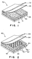
- the sandwich structure 50 has a core including core members 51 of a closed-cell foam plastic material, and surface plates 52 and 53 of a fiber-reinforced composite material covering the opposite surfaces of the core, respectively.
- the closed-cell, foam plastic material is , for example, a closed-cell foam polymethacrylimide (PMI) or a closed-cell foam polyvinyl chloride (PVC).
- the surface plates 52 and 53 are formed of a fiber-reinforced composite material containing hydrophobic inorganic fibers, such as carbon fibers, as reinforcing fibers.
- Each of the surface plates 52 and 53 is formed by laminating a plurality of prepreg sheets each formed by impregnating a sheet of the reinforcing fibers with an epoxy resin or the like.
- the core members 51 are bonded together with an adhesive film 54 of an adhesive that does not foam, such as Cytec FM300K®.
- the surface plates 52 and 53 are bonded to the core members 51 with adhesive films 55 of an adhesive, such as Cytec FM300U®, not containing any carrier.
- the surface plates 52 and 53 can be bonded to the core members 51 without forming any gaps between the surface plates 52 and 53 and the core members 51 by the adhesive films 55. Consequently, water is unable to leak into the sandwich structure 50.
- the surface plates 52 and 53 may be bonded to the core members 51 by using the resin of the composite material forming the surface plates 52 and 53 instead of using the adhesive films 55.
- Prepreg sheets for forming the surface plates 52 and 53 may be superposed on the opposite surfaces of the opposite surfaces of the core consisting of the core members 51, and heat and pressure may be applied to the prepreg sheets for setting to bond the surface plates 52 and 53 to the core members 51.
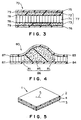
- the sandwich structure 60 has a core 67, and surface plates 62 and 63.
- the surface plates 62 and 63 similarly to the surface plates 52 and 53 of the sandwich structure 50 in the first embodiment, are formed of a fiber-reinforced composite material containing hydrophobic inorganic fibers as reinforcing fibers.
- the surface plates 62 and 63 are bonded to the opposite surfaces of the core 67 with adhesive films 64 not containing any carrier or with the resin of the fiber-reinforced composite material, respectively.
- the core 67 has a honeycomb core member 66 and foam plastic core members 61 of a closed-cell plastic material surrounding the honeycomb core member 66 and bonded together with adhesive films 65 that do not foam.
- the honeycomb core member 66 has high strength and rigidity to withstand force that acts thereon in a direction along the thickness of the sandwich structure 60 and low strength and rigidity to withstand force that acts thereon in a direction perpendicular to the direction along the thickness of the sandwich structure 60. Therefore, when heating and pressing a sandwich structure provided with a honeycomb core, the sandwich structure must be placed in a metal locating jig having the shape of a frame or a peripheral part of the sandwich structure must be gently tapered to prevent the sandwich structure from being crushed by lateral pressure.
- the sandwich structure 60 is provided with the core 67 including the foam plastic core members 61 arranged in the shape of a frame so as to surround the honeycomb core member 66, the sandwich structure 60 has high strength to withstand lateral force, and a peripheral part of the sandwich structure 60 can be sharply tapered.
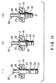
- the sandwich structure 70 has a core 77 including foam plastic core members 72 and 73 of a closed-cell foam plastic material and a honeycomb core member 71 sandwiched between the foam plastic core members 72 and 73, and surface plates 75 and 76 bonded to the opposite surfaces of the core 77, respectively.
- the foam plastic core members 72 and 73 are bonded to the honeycomb core member 71 with adhesive films 78 not containing any carrier.
- the surface plates 75 and 76 are bonded to the core 77 with adhesive films 79 not containing any carrier..
- the surface plates 75 and 75 are formed of a fiber-reinforced composite material containing hydrophobic inorganic fibers.
- honeycomb core member 71 Since the honeycomb core member 71 is sandwiched between the foam plastic core members 72 and 73, water is unable to leak into the sandwich structure 70 even if the surface plate 75 or 76 is fissured. Since the foam plastic core members 72 and 73 capable of absorbing shocks are contiguous with the surface plates 775 and 76, the sandwich structure 70 is resistant to damaging actions.
- the sandwich structure 80 has a core 86 including honeycomb core members 81 and a foam plastic core member 85, and surface plates 83 and 84.
- the honeycomb core members 81 are disposed in portions of the sandwich structure 80 in which the thickness of the sandwich structure 80 varies in a narrow range
- the foam plastic core member 85 is disposed in a portion of the sandwich structure 80 in which the thickness of the sandwich structure 80 varies in a wide range.
- the sandwich structure 80 in the fourth embodiment is provided with the core 86 including the honeycomb core members 81 disposed in portions of the sandwich structure 80 in which the thickness of the sandwich structure 80 varies in a narrow range, and the foam plastic core member 85 disposed in a portion of the sandwich structure 80 in which the thickness of the sandwich structure 80 varies in a wide range.
- the core 81 can be easily formed.
- the surface plates 83 and 84 are formed by laminating prepreg sheets on the core 86.
- the surface plates 83 and 84 are bonded to the core 86 with adhesive films 87 not containing any carrier.
- the surface plates 83 and 84 are formed of a fiber-reinforced composite material containing hydrophobic inorganic fibers.
- Fig. 5 shows a damaged sandwich structure 1.
- the sandwich structure 1 is a composite structure and has a flat core 4 of 12.7 mm in thickness and surface plates 2 and 3 covering the opposite surfaces of the core 4.
- the core 4 is formed of a closed-cell foam plastic material.
- the surface plates 2 and 3 are formed of a fiber-reinforced composite material containing hydrophobic inorganic fibers.
- the sandwich structure 1 is used as a skin of, for example, aircraft or rolling stock, such as a high-speed passenger car for a rapid train.
- the surface plates 2 and 3 serve as an outer surface plate and an inner surface plate, respectively.
- the outer surface plate 2 is formed of a fiber-reinforced composite material formed by laminating eight prepreg sheets each formed by impregnating a sheet of reinforcing fibers with a resin.
- the inner surface plate 3 is fanned of a fiber-reinforced composite material formed by laminating four prepreg sheets and is thinner than the outer surface plate 2.
- a fissure 5 is formed in the outer surface plate 2 of the sandwich structure 1 and the outer surface plate 2 needs repair.
- a portion of the outer surface plate 2 having the fissure 5 is cut out with a hole saw 11 as shown in Fig. 6 to form a round opening 10 in the outer surface plate 2.
- the hole saw 11 has the shape of a hollow cylinder with cutting teeth 12 around its edge. The hole saw 11 is rotated at a high rotating speed about its axis to cut a round hole.
- the hole saw 11 has a diameter greater than that of a circular region including the fissure 5 in the outer surface plate 2. Since the portion including the fissure 5 of the outer surface plate 2 is cut out in a circular shape, the intensity of stress concentration can be limited to a low level.
- the diameter of the hole saw 11 is, for example, 50 mm.
- a cylindrical portion of the core 4 underlying the outer surface plate 2 is cut out together with the round portion of the outer surface plate 2, so that the round opening 10 is formed in the outer surface plate 2.
- Figs. 7 and 8 are views of assistance in explaining work for removing portions of the core 4. Portions of the core 4 corresponding to the opening 10 and around the edge of the opening 10 are removed. Since the core 4 is formed of a closed-cell foam plastic material and the surface plates 2 and 3 are formed of a fiber-reinforced composite material, only the portions of the core 4 can be efficiently removed by shot blasting using shot, such as walnut power or particles of alumina or corn. The shot is blown through a nozzle 15 against the core 4 to scrape off portions of the core 4. An end portion of the nozzle 15 is bent substantially through an angle of 180° as shown in Fig. 8 to facilitate removing a portion of the core 4 around the edge of the opening 10 formed in the outer surface plate 2.
- shot such as walnut power or particles of alumina or corn.
- shot is blown through a nozzle 15 against the core 4 to scrape off portions of the core 4.
- An end portion of the nozzle 15 is bent substantially through an angle of 180° as shown in Fig. 8 to facilitate
- a support plate 16 is inserted in a hole formed in the sandwich structure 1 as shown in Figs. 9 and 10.
- the support plate 16 is an expandable plate having a circular central part 17 and rectangular radial arms 18 (eight radial arms in this embodiment) like petals of a flower as shown in Fig. 9.
- the support plate 16 is made of, for example, a titanium alloy.
- the support plate 16 can be formed by punching a titanium alloy sheet.
- the diameter of the circular central part 17 is smaller than that of the opening 10.
- the diameter of an imaginary circle circumscribed about the support plate 16 is far greater than that of the opening 10.
- the support plate 16 is inserted through the opening 10 in the space formed by removing the portions of the core 4.
- the arms 18 are curved inward and the arms 18 are extended in the space after the support plate 16 has been entirely inserted into the space.
- through holes 24 for passing rivets 25 are formed through the outer surface plate 2 and the arms 18 with a drill.
- the through holes 24 may be formed in the outer surface plate 2 and the arms 18 before inserting the support plate 16 into the space.
- the arms 18 are fastened to the inner surface of a portion of the outer surface plate 2 around the edge of the opening 10 with the rivets 25 as shown in Fig. 10.
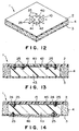
- the rivets 25 are blind rivets that can be staked from one side thereof.
- Each rivet 25 has a countersunk flat head 26 that can be set flush with the outer surface of the outer surface plate 2.
- the rivet 27 has a hollow rod 27 and a draw bar 28 inserted in the hollow rod 27.
- a sleeve 30 is put on an inner end portion of the draw bar 28 projecting from the hollow rod 27, and the inner end of the draw bar 28 is connected to a solid core bolt 31 formed at the extremity of the sleeve 30.
- a coiled washer 32 is disposed on the base end of the sleeve 30.
- An inner end portion of the hollow rod 27 is tapered.
- the rivet 25 is inserted from the outside of the outer surface plate 2 in the through holes 24 formed in the outer surface plate 2 and the arm 18, and then the draw bar 28 is pulled outward by a tool. Then, the coiled washer 32 is uncoiled and expanded by the tapered inner end portion of the hollow rod 27 as shown in Fig. 11(2). As the draw bar 28 is pulled further outward, the coiled washer 32 is brought into contact with the inner surface of the arm 18 of the support plate 16 and the sleeve 30 is fully staked. Then, a portion of the draw bar 28 projecting outward from the head 26 is cut off. Thus, the eight arms 18 of the support plate 16 are fastened to the outer surface plate 2 with the rivets 25.
- a cover plate 40 is seated on the support plate 16 in the opening 10 as shown in Fig. 12.
- the cover plate 40 is a circular plate formed by cutting a plate of the same fiber-reinforced composite material as that forming the outer surface plate 2 with the hole saw 11. Since the circular central part 17 of the support plate 16 lies in the opening 10 and the arms 18 are fastened to the inner surface of the outer surface plate 2, the cover plate 40 is seated on the circular central part 17. Then, eight through holes are formed through the cover plate 40 and the support plate 16 with a drill at eight positions corresponding to the eight arms 18. Blind rivets 25 are inserted in the through holes and are staked by the same method as that mentioned above to fasten the cover plate 40 to the circular central part 17 with the rivets 25. Since the thickness of the cover plate 40 is equal to that of the outer surface plate 2, the outer surface of the cover plate 40 fastened to the support plate 16 is flush with the outer surface of the outer surface plate 2.
- a filling material 43 is injected through the through hole 41 into the space formed in the sandwich structure 1 by means of an injection gun.
- the filling material 43 is a liquid foaming resin containing minute bubbles.
- the space formed by removing the portions of the core 4 is filled up with the filling material 43 as shown in Fig. 13.
- the filling material 43 overflows through the other through hole 42, which indicates that the space has been fully filled with the filling material 43.
- the filling material 43 injected into the space sets perfectly in a predetermined time. The filling material sets at an ordinary temperature.
- the damaged sandwich structure 1 can be easily repaired by using the rivets 25 without requiring any special devices.
- the titanium alloy forming the support plate 16 has a coefficient of thermal expansion nearer to that of the fiber-reinforced composite material forming the surface plates 2 and 3 than those of aluminum alloys. Therefore, an excessively high thermal stress will not be induced in the support plate 16 while the sandwich structure 1 is in use even though the support plate 16 is fastened to the outer surface plate 2 with the rivets 25.
- the sandwich structure repairing method may use a support means other than the support plate 16 having the radial arms 18.
- a support means other than the support plate 16 having the radial arms 18.
- a plurality of support plates may be fastened to the inner surface of a portion of the outer surface plate 2 around the edge of the opening 10 with rivets so as to protrude into the opening 10, and the cover plate 40 may be placed on and fastened with rivets to the support plates.
- a cylindrical portion of the sandwich structure 1 including portions of the outer surface plate 2, the core 4 and the inner surface plate 3 may be removed with the hole saw 11 to form a cylindrical space extending through the sandwich structure 1.
- the cylindrical space permits the repairing work to be performed on both the outer and the inner side of the sandwich structure 1 and facilitates the work for removing a portion of the core 4 around the edge of the opening in the outer surface plate 2. Since the inner surface of the sandwich structure 1 is out of view and need not be entirely flat, a cover plate of a diameter greater than that of an opening formed in the back surface plate 3 may be fastened with rivets directly to the inner surface plate 3 so as to cover the opening in the inner surface plate 3.
- FIG. 14 A sandwich structure repairing method in a sixth embodiment according to the present invention will be explained hereinafter with reference to Fig. 14, in which parts like or corresponding to those shown in Figs. 5 to 13 are denoted by the same reference characters and the description thereof will be omitted.
- the sandwich structure repairing method is used when repairing work can be performed on the side of an inner surface plate 3 of a sandwich structure 1.
- the sandwich structure 1 has a flaw 5 in an outer surface plate 2 thereof.
- a portion of the inner surface plate 3 corresponding to a portion of the outer surface plate 2 having the flaw 5 is removed with a hole saw 11 to form an opening, and a portion of a core 4 corresponding to the portion having the flaw 5 is removed by shot blasting as mentioned above.
- a mending plate (as an outer support plate) 45 is put on the inner surface of the portion of the outer surface plate 2 having the flaw 5 and is fastened to the outer surface plate 2 with rivets 25.
- the mending plate 45 is formed of a titanium alloy or the same fiber-reinforced composite material as that forming the outer surface plate 2. Then, a space formed by removing a portion of the core 4 is filled up with a filling material 43 and a cover plate (as an inner support plate )46 is fastened to the inner surface plate 3 with rivets 25 so as to cover the opening formed in the inner surface plate 3. Thus, any opening does not need to be formed in the outer surface plate 2.
- This sandwich structure repairing method is applicable not only to repairing a sandwich structure provided with only a foam plastic core, but also to repairing sandwich structures provided with a core consisting of honeycomb core members and foam plastic core members as those shown in Figs. 2 to 4.
- a sandwich structure includes a core having foam plastic core members of a closed-cell foam plastic material, and composite surface plates of a fiber-reinforced composite material containing hydrophobic inorganic fibers as reinforcing fibers and covering the opposite surfaces of the core, wherein the foam plastic core members are bonded together with an adhesive film that does not foam, and the composite surface plates are bonded to the core with adhesive films not containing any carrier or a component resin of the fiber-reinforced composite material forming the surface plates.
- a peripheral part of the core is formed of the foam plastic core members arranged so as to surround the honeycomb core members. Therefore, the sandwich structure has a high strength and a high rigidity.
- the core is formed by sandwiching the honeycomb core members between the foam plastic core members and bonding the foam plastic core members to the honeycomb core members with adhesive films not containing any carrier. Therefore, water is unable to penetrate into the sandwich structure and the sandwich structure has a high strength and a high rigidity.
- portions of the core corresponding to portions of the sandwich structure where thickness varies sharply are formed of the foam plastic core members and portions of the core corresponding to portions of the sandwich structure where thickness varies gradually are formed of the honeycomb core members. Therefore, the core can be easily processed and the composite surface plates can be easily bonded to the core.
- the sandwich structure repairing method puts the outer support plate to the inner surface of the outer surface plate and fastens the same to the outer surface plate with the rivets. Since the outer support plate is attached to the outer surface plate by riveting work using rivets for repair instead of bonding work using an adhesive that requires time and labor, time and labor necessary for repairing the sandwich structure can be greatly reduced.
- the sandwich structure repairing method removes a damaged portion of the outer surface plate to form an opening, attaches the outer support plate to the inner surface of a portion of the outer surface plate around the edge of the opening with the rivets, and fits the cover plate in the opening and fastens the same to the support plates.
- the sandwich structure can be repaired so that the outer surface thereof is flat and smooth.
- a portion of the foam plastic core member can be easily removed by shot blasting, which reduces repairing time greatly.
Landscapes
- Engineering & Computer Science (AREA)
- Mechanical Engineering (AREA)
- Laminated Bodies (AREA)
Abstract
Description
Claims (11)
- A sandwich structure comprising:a core having foam plastic core members formed of a closed-cell foam plastic material; andsurface plates formed of a fiber-reinforced composite material containing hydrophobic inorganic fibers as reinforcing fibers and covering the opposite surfaces of the core;
wherein the foam plastic core members are bonded together with adhesive films that do not foam, and the surface plates are bonded to the core with adhesive films not containing any carrier or a component resin of the fiber-reinforced composite material forming the surface plates. - A sandwich structure comprising:a core having foam plastic core members formed of a closed-cell foam plastic material and honeycomb core members; andsurface plates formed of a fiber-reinforced composite material containing hydrophobic inorganic fibers as reinforcing fibers and covering the opposite surfaces of the core;
wherein a peripheral part of the core is formed of the foam plastic core members arranged so as to surround the honeycomb core members, the foam plastic core members are bonded together with adhesive films that do not foam, and the surface plates are bonded to the core with adhesive films not containing any carrier or a component resin of the fiber-reinforced composite material forming the surface plates. - A sandwich structure comprising:a core having foam plastic core members formed of a closed-cell foam plastic material and honeycomb core members; andsurface plates formed of a fiber-reinforced composite material containing hydrophobic inorganic fibers as reinforcing fibers and covering the opposite surfaces of the core;
wherein the core is formed by sandwiching the honeycomb core members between the foam plastic core members and bonding the foam plastic core members to the honeycomb core members with adhesive films not containing any carrier. - A sandwich structure comprising:a core having foam plastic core members formed of a closed-cell foam plastic material and honeycomb core members; andsurface plates formed of a fiber-reinforced composite material containing hydrophobic inorganic fibers as reinforcing fibers and covering the opposite surfaces of the core;
wherein portions of the core corresponding to portions of the sandwich structure where thickness varies sharply are formed of the foam plastic core members, portions of the core corresponding to portions of the sandwich structure where thickness varies gradually are formed of the honeycomb core members, and the surface plates are bonded to the core with adhesive films not containing any carrier or a component resin of the fiber-reinforced composite material forming the surface plates. - The sandwich structure according to any one of claims 1 to 4 to be used as a structural member of aircraft, rolling stock, an automobile or a ship.
- A sandwich structure repairing method of repairing a sandwich structure comprising a core having foam plastic core members formed of a closed-cell foam plastic material, and an outer surface plate and an inner surface plate formed of a fiber-reinforced plastic material and bonded to the opposite surfaces of the core with adhesive films not containing any carrier or a component resin of the fiber-reinforced composite material forming the surface plates, said sandwich structure repairing method comprising the steps of:putting an outer support plate to an inner surface of a damaged portion of the outer surface plate; andfastening the outer support plate to the outer surface plate with rivets.
- The sandwich structure repairing method according to claim 6, wherein:a portion of the inner surface plate and a portion of the core corresponding to the damaged portion of the outer surface plate are removed;the outer support plate is fastened to the inner surface of the damaged portion of the outer surface plate with rivets;a cavity formed by removing the portion of the core is filled up with a filling material; andan inner support plate of a size greater than that of an opening in the inner surface plate formed by removing the portion of the inner surface plate is fastened to the inner surface plate with rivets so as to cover the opening in the inner surface plate.
- The sandwich structure repairing method according to claim 6, wherein:an opening is formed in the damaged portion of the outer surface plate;a portion of the core and a portion of the inner surface plate corresponding to the opening and a region around an edge of the opening are removed;the outer support plate is fastened to the inner surface of a portion of the outer surface plate around an edge of the opening in the outer surface plate with rivets;a cover plate formed of the same material as that forming the outer surface plate and having a thickness equal to that of the outer surface plate is fitted in the opening and is fastened to the outer support plate with rivets;a cavity formed in the core by removing the portion of the core is filled up with a filling material; andan inner support plate of a size greater than that of an opening in the inner surface plate formed by removing the portion of the inner surface plate is fastened to the inner surface plate with rivets so as to cover the opening in the inner surface plate.
- The sandwich structure repairing method according to claim 6, wherein:a portion of the outer surface plate including the damaged portion is removed to form an opening in the outer surface plate;a portion of the core corresponding to the opening in the outer surface plate and a portion of the core around an edge of the opening in the outer surface plate are removed;the outer support plate is expandable over a region greater than the opening in the outer surface plate;the outer support plate is inserted through the opening in the outer surface plate;the outer support plate is fastened to the inner surface of the outer surface plate with rivets;a cover plate of a size equal to that of the opening formed in the outer surface plate and of a thickness equal to that of the outer surface plate is fitted in the opening in the outer surface plate;the outer support plate is fastened to the support plate with rivets; anda cavity formed by removing the portions of the core is filled up with a filling material.
- The sandwich structure repairing method according to claim 6, wherein:a plurality of the outer support plates are used;a portion of the outer surface plate including the damaged portion is removed to form an opening in the outer surface plate;a portion of the core corresponding to the opening in the outer surface plate and a portion of the core around an edge of the opening in the outer surface plate are removed;the plurality of the outer support plates are inserted through the opening in the outer surface plate so as to be arranged on the inner surface of a portion of the outer surface plate around an edge of the opening in the outer surface plate;the plurality of the outer support plates are fastened to the inner surface of the outer surface plate with rivets;a cover plate of a size equal to that of the opening formed in the outer surface plate and of a thickness equal to that of the outer surface plate is fitted in the opening in the outer surface plate;the cover plate is fastened to the plurality of the outer support plates with rivets; anda cavity formed by removing the portions of the core is filled up with a filling material.
- The sandwich structure repairing method according to any one of claims 6 to 10, wherein the portion of the core of a foam plastic material are removed by a shot blasting process.
Applications Claiming Priority (2)
| Application Number | Priority Date | Filing Date | Title |
|---|---|---|---|
| JP21776599 | 1999-07-30 | ||
| JP21776599A JP3243461B2 (en) | 1999-07-30 | 1999-07-30 | Sandwich structure |
Publications (3)
| Publication Number | Publication Date |
|---|---|
| EP1072396A2 true EP1072396A2 (en) | 2001-01-31 |
| EP1072396A3 EP1072396A3 (en) | 2001-11-07 |
| EP1072396B1 EP1072396B1 (en) | 2006-06-14 |
Family
ID=16709392
Family Applications (1)
| Application Number | Title | Priority Date | Filing Date |
|---|---|---|---|
| EP00116536A Expired - Lifetime EP1072396B1 (en) | 1999-07-30 | 2000-07-31 | Sandwich structure and method of repairing the same |
Country Status (5)
| Country | Link |
|---|---|
| US (1) | US6770349B2 (en) |
| EP (1) | EP1072396B1 (en) |
| JP (1) | JP3243461B2 (en) |
| CA (1) | CA2314678C (en) |
| DE (1) | DE60028663T2 (en) |
Cited By (16)
| Publication number | Priority date | Publication date | Assignee | Title |
|---|---|---|---|---|
| WO2003080304A3 (en) * | 2002-03-18 | 2004-12-09 | Electrolux Professional Outdoor Products Inc | Movable machines having a housing of a fibre-reinforced composite material |
| WO2006028107A1 (en) | 2004-09-07 | 2006-03-16 | Toray Industries, Inc. | Sandwich structure and integrated formed article using the same |
| GB2455063A (en) * | 2007-11-12 | 2009-06-03 | Rolls Royce Plc | Method of repairing a lined structure |
| US7757684B2 (en) | 2002-03-18 | 2010-07-20 | Electrolux Professional Outdoor Products, Inc. | Movable machinery, including pavement working apparatus and methods of making |
| EP2727712A1 (en) * | 2012-10-30 | 2014-05-07 | Bell Helicopter Textron Inc. | Method of repairing, splicing, joining, machining, and stabilizing honeycomb core using pourable structural foam and a structure incorporating the same |
| US9149999B2 (en) | 2012-10-30 | 2015-10-06 | Bell Helicopter Textron Inc. | Method of repairing, splicing, joining, machining, and stabilizing honeycomb core using pourable structural foam and a structure incorporating the same |
| EP2930011A1 (en) * | 2014-04-07 | 2015-10-14 | AIRBUS HELICOPTERS DEUTSCHLAND GmbH | A method of repairing a sandwich component having a honeycomb core with an associated core height |
| DK178484B1 (en) * | 2011-03-08 | 2016-04-11 | Gen Electric | Procedure for repairing a wind turbine blade |
| US9333684B2 (en) | 2012-10-30 | 2016-05-10 | Bell Helicopter Textron Inc. | Method of repairing, splicing, joining, machining, and stabilizing honeycomb core using pourable structural foam and a structure incorporating the same |
| EP2992149A4 (en) * | 2013-05-02 | 2016-06-01 | Tower Ipco Co Ltd | MULTI-OBJECTIVE TILE |
| US9597826B2 (en) | 2012-10-30 | 2017-03-21 | Bell Helicopter Textron Inc. | Method of repairing, splicing, joining, machining, and stabilizing honeycomb core using pourable structural foam and a structure incorporating the same |
| DE102016222435A1 (en) | 2016-11-15 | 2018-05-17 | Deutsches Zentrum für Luft- und Raumfahrt e.V. | Sandwich element, load-bearing structure and vehicle |
| FR3062806A1 (en) * | 2017-02-15 | 2018-08-17 | Safran Nacelles | PROCESS FOR MACHINING A COMPOSITE MATERIAL, IN PARTICULAR FOR THE REPAIR OF THE COMPOSITE MATERIAL |
| NL2018851B1 (en) * | 2017-05-05 | 2018-11-14 | Johannes Franciscus Maria Van Veldhoven Mattheus | Method for repairing damage to an insulated body of a vehicle and repaired vehicle. |
| CN110962377A (en) * | 2018-09-28 | 2020-04-07 | 成都飞机工业(集团)有限责任公司 | Honeycomb sandwich structure part repairing method capable of reducing structure loss |
| FR3100745A1 (en) * | 2019-09-16 | 2021-03-19 | Safran Nacelles | Repair process for thermal protection of a nacelle structure |
Families Citing this family (51)
| Publication number | Priority date | Publication date | Assignee | Title |
|---|---|---|---|---|
| EP1688238A1 (en) * | 2005-02-02 | 2006-08-09 | Saab Ab | Method for repair of composite articles |
| JP2006198866A (en) * | 2005-01-20 | 2006-08-03 | Mitsubishi Rayon Co Ltd | Core material for sandwich structure material and method for producing sandwich structure material |
| US8367183B2 (en) | 2005-06-08 | 2013-02-05 | Kabushiki Kaisha Shizuka | Sandwich panel including honeycomb structure body and method of producing the sandwich panel |
| US20080260992A1 (en) * | 2005-06-08 | 2008-10-23 | Kabushiki Kaisha Shizuka | Sandwich Panel Including Honeycomb Structure Body and Method of Producing the Sandwich Panel |
| JP5208759B2 (en) | 2005-11-30 | 2013-06-12 | エアバス オペレーションズ、ソシエダ リミタダ | Composite structure embedded with optical fiber and repair method thereof |
| ES2457023T3 (en) | 2005-11-30 | 2014-04-24 | Airbus Operations S.L. | Structure of composite fiber optic material embedded in one of its surface layers and procedure for connection and repair |
| DE102007003273A1 (en) * | 2007-01-23 | 2008-07-24 | Airbus Deutschland Gmbh | Localized processing of reinforced foam materials as well as composite core components |
| US7891096B2 (en) * | 2007-01-23 | 2011-02-22 | Airbus Deutschland Gmbh | Method for reinforcing a foam material as well as a sandwich component |
| US7842147B2 (en) * | 2007-01-31 | 2010-11-30 | M.C. Gill Corporation | Composite panel having in-situ thermoset foamed core |
| US8108979B2 (en) * | 2007-04-24 | 2012-02-07 | United Technologies Corporation | Using a stiffener to repair a part for an aircraft engine |
| GB2448901A (en) * | 2007-05-02 | 2008-11-05 | Alderley Materials Ltd | Thermal Insulation Structure |
| US8371009B2 (en) * | 2007-12-12 | 2013-02-12 | General Electric Company | Methods for repairing composite containment casings |
| US8403624B2 (en) * | 2007-12-12 | 2013-03-26 | General Electric Company | Composite containment casings having an integral fragment catcher |
| US7981519B2 (en) * | 2008-04-11 | 2011-07-19 | United Technologies Corporation | Metallic doubler for repair of a gas turbine engine part |
| US20090313931A1 (en) * | 2008-06-24 | 2009-12-24 | Porter William H | Multilayered structural insulated panel |
| US20100014935A1 (en) * | 2008-07-21 | 2010-01-21 | Fred Jevaney | Reinforced bulkheads and methods of making same |
| JP4860730B2 (en) * | 2009-07-24 | 2012-01-25 | 株式会社イノアックコーポレーション | Lightweight honeycomb panel |
| DE102009035108B4 (en) * | 2009-07-29 | 2013-02-07 | Airbus Operations Gmbh | Method and spraying device for repairing a sandwich panel |
| US20120272592A1 (en) * | 2009-10-28 | 2012-11-01 | Carmen Bellavia | Light weight molded roof tile with integrated solar capabilities |
| WO2011071318A2 (en) * | 2009-12-10 | 2011-06-16 | Cho Hyun-Chul | Board having a built-in member, heat insulation structure, and ship in which the ingress of water is prevented |
| WO2011105540A1 (en) * | 2010-02-26 | 2011-09-01 | 三菱重工業株式会社 | Composite material repair method, and composite material using same |
| EP2595876B1 (en) * | 2010-07-20 | 2016-07-06 | Airbus Operations GmbH | Lining shell carrying a main load and structural component having at least one lining shell carrying a main load |
| DE102010053569B4 (en) | 2010-12-06 | 2012-07-26 | Airbus Operations Gmbh | Method for repairing an aircraft structural component |
| MX2013008280A (en) * | 2011-01-18 | 2014-01-08 | Leoni Kabel Holding Gmbh | Apparatus for the automated feed of connecting elements to a processing unit and feed hose for the connecting elements. |
| US8844108B2 (en) * | 2011-07-12 | 2014-09-30 | The Boeing Company | Large area repair of composite aircraft |
| JP5818700B2 (en) | 2012-01-19 | 2015-11-18 | 三菱航空機株式会社 | Repair method and repair structure of honeycomb sandwich structure |
| EP2792630A1 (en) * | 2013-04-16 | 2014-10-22 | Kone Corporation | An elevator car and an elevator |
| US8985513B2 (en) * | 2013-06-17 | 2015-03-24 | The Boeing Company | Honeycomb cores with splice joints and methods of assembling honeycomb cores |
| DE102013018148B4 (en) * | 2013-12-04 | 2015-07-30 | Premium Aerotec Gmbh | Process for the production of a fiber composite component, as well as semifinished assembly usable therefor |
| DE102013225730A1 (en) * | 2013-12-12 | 2015-06-18 | Bayerische Motoren Werke Aktiengesellschaft | Honeycomb sandwich structure and method for producing a honeycomb sandwich structure |
| EP3152044A4 (en) | 2014-06-04 | 2017-12-20 | Bright Lite Structures LlC | Composite structure exhibiting energy absorption and/or including a defect free surface |
| JP6215167B2 (en) * | 2014-09-29 | 2017-10-18 | 積水化成品工業株式会社 | Fiber reinforced composite and method for producing fiber reinforced composite |
| JP6602391B2 (en) | 2015-04-03 | 2019-11-06 | ブライト ライト ストラクチャーズ エルエルシー | Apparatus and associated method for controllably cutting fibers |
| US10828484B2 (en) | 2015-08-21 | 2020-11-10 | Medline Industries, Inc. | Disinfecting cap |
| CN106079675B (en) * | 2016-06-30 | 2019-01-25 | 中铁伟业(北京)新技术有限公司 | Composite board for train |
| CN106226393B (en) * | 2016-07-05 | 2020-01-31 | 国营芜湖机械厂 | layered damage repairing method for laminated composite material structure |
| EP4046783B1 (en) * | 2016-10-25 | 2024-05-01 | Rohr, Inc. | Acoustic panel repair with retention of acoustic properties |
| US10604226B2 (en) * | 2017-04-14 | 2020-03-31 | Textron Innovations Inc. | Shielded structure for aircraft |
| US10946600B1 (en) * | 2017-08-29 | 2021-03-16 | Hrl Laboratories, Llc | Composite structure repair methods incorporating a lattice core material |
| US11148375B1 (en) | 2017-08-29 | 2021-10-19 | Hrl Laboratories, Llc | Method of repairing sandwich structure and repaired sandwich structure |
| RU2664620C1 (en) * | 2017-10-20 | 2018-08-21 | Российская Федерация, От Имени Которой Выступает Министерство Промышленности И Торговли Российской Федерации | Polymer composite materials three-layer panels repairing method |
| CN109649679A (en) * | 2018-10-15 | 2019-04-19 | 西北工业大学 | Plate repair method |
| WO2020106678A1 (en) | 2018-11-19 | 2020-05-28 | Bright Lite Structures Llc | High-strength low-heat release composites cross-reference to related applications |
| CN110332451B (en) * | 2019-05-23 | 2025-04-04 | 久泰能源(准格尔)有限公司 | High-strength plastic honeycomb core material with internal support and its preparation process |
| US11312507B2 (en) * | 2019-09-03 | 2022-04-26 | The Boeing Company | Repair assembly to repair an area on a member of a vehicle |
| CN113370605A (en) * | 2021-05-18 | 2021-09-10 | 上海市富力达科技股份有限公司 | Carbon fiber composite material plate with sandwich structure and preparation process thereof |
| US12053943B2 (en) * | 2021-07-08 | 2024-08-06 | The Boeing Company | Method for repairing composite structures using foamable media |
| CN113478946A (en) * | 2021-07-12 | 2021-10-08 | 重庆泛锐科技有限公司 | Repairing method of sandwich composite material plate |
| CN114368173B (en) * | 2021-11-24 | 2023-07-07 | 中国南方航空股份有限公司 | Typical gradual change step type hyperbolic laminate structure penetrating damage repair process |
| CN115609946B (en) * | 2022-09-15 | 2025-09-12 | 南京玻璃纤维研究设计院有限公司 | Sliding honeycomb preform shaping mold and method |
| EP4610034A1 (en) * | 2024-02-28 | 2025-09-03 | Airbus Operations GmbH | Method and repair kit for repairing a sandwich structure |
Family Cites Families (17)
| Publication number | Priority date | Publication date | Assignee | Title |
|---|---|---|---|---|
| US3619344A (en) | 1969-08-07 | 1971-11-09 | Du Pont | Oriented foam laminar structures |
| US4120712A (en) | 1975-03-17 | 1978-10-17 | The Boeing Company | Method of securing two non-metal surfaces together using a hot melt type fastener heatable by induction heating |
| GB2032843B (en) * | 1978-10-31 | 1982-07-14 | Coal Ind | Foamed phenolic board laminate |
| US4351873A (en) * | 1980-07-31 | 1982-09-28 | Gaf Corporation | Double faced insulating board |
| FR2525849B1 (en) * | 1982-04-26 | 1985-08-09 | Hutchinson | PRINTED CIRCUIT SUBSTRATE |
| WO1984004727A1 (en) * | 1983-05-27 | 1984-12-06 | Boeing Co | Lightweight, fire-retardant structural panel |
| US4749601A (en) | 1985-04-25 | 1988-06-07 | Hillinger Brad O | Composite structure |
| WO1987003842A1 (en) * | 1985-12-19 | 1987-07-02 | Built-Rite Productions Pty. Limited | Refurbishment of fibreglass panels |
| US4687691A (en) * | 1986-04-28 | 1987-08-18 | United Technologies Corporation | Honeycomb spliced multilayer foam core aircraft composite parts and method for making same |
| US5328744A (en) * | 1990-10-09 | 1994-07-12 | E. I. Du Pont De Nemours And Company | Panel having a core with thermoplastic resin facings |
| AU650769B2 (en) | 1991-08-05 | 1994-06-30 | 3A Technology & Management Ltd. | Process for the production of a composite sheet comprising a cellular core and at least one outer layer |
| US5313034A (en) | 1992-01-15 | 1994-05-17 | Edison Welding Institute, Inc. | Thermoplastic welding |
| US5462623A (en) | 1992-05-04 | 1995-10-31 | Webcore Technologies, Inc. | Method of production of reinforced foam cores |
| JPH06173170A (en) | 1992-12-04 | 1994-06-21 | Sumika Hercules Kk | Sizing agent composition for reinforcing fiber |
| US5589016A (en) * | 1994-04-29 | 1996-12-31 | The Boeing Company | Prescored foam for panel fabrication |
| US5580502A (en) * | 1995-03-23 | 1996-12-03 | Sikorsky Aircraft Corporation | Method of fabricating a composite article having an integral, co-cured composite stiffening member |
| IL114613A (en) | 1995-07-16 | 1999-09-22 | Tat Ind Ltd | Parallel flow condenser heat exchanger |
-
1999
- 1999-07-30 JP JP21776599A patent/JP3243461B2/en not_active Expired - Lifetime
-
2000
- 2000-07-28 CA CA002314678A patent/CA2314678C/en not_active Expired - Lifetime
- 2000-07-31 DE DE60028663T patent/DE60028663T2/en not_active Expired - Lifetime
- 2000-07-31 EP EP00116536A patent/EP1072396B1/en not_active Expired - Lifetime
-
2003
- 2003-08-08 US US10/636,566 patent/US6770349B2/en not_active Expired - Lifetime
Cited By (24)
| Publication number | Priority date | Publication date | Assignee | Title |
|---|---|---|---|---|
| WO2003080304A3 (en) * | 2002-03-18 | 2004-12-09 | Electrolux Professional Outdoor Products Inc | Movable machines having a housing of a fibre-reinforced composite material |
| US6955167B2 (en) | 2002-03-18 | 2005-10-18 | Electrolux Professional Outdoor Products, Inc. | Pavement working apparatus and methods of making |
| US7018279B2 (en) | 2002-03-18 | 2006-03-28 | Electrolux Professional Outdoor Products, Inc. | Movable machinery, including pavement working apparatus and methods of making |
| US7757684B2 (en) | 2002-03-18 | 2010-07-20 | Electrolux Professional Outdoor Products, Inc. | Movable machinery, including pavement working apparatus and methods of making |
| WO2006028107A1 (en) | 2004-09-07 | 2006-03-16 | Toray Industries, Inc. | Sandwich structure and integrated formed article using the same |
| EP1803551A4 (en) * | 2004-09-07 | 2012-02-29 | Toray Industries | SANDWICH STRUCTURE AND INTEGRATED MOLD OBJECT USING THE SAME |
| EP2527139A1 (en) * | 2004-09-07 | 2012-11-28 | Toray Industries, Inc. | Sandwich structure and integrated formed article using the same |
| GB2455063A (en) * | 2007-11-12 | 2009-06-03 | Rolls Royce Plc | Method of repairing a lined structure |
| DK178484B1 (en) * | 2011-03-08 | 2016-04-11 | Gen Electric | Procedure for repairing a wind turbine blade |
| US9597826B2 (en) | 2012-10-30 | 2017-03-21 | Bell Helicopter Textron Inc. | Method of repairing, splicing, joining, machining, and stabilizing honeycomb core using pourable structural foam and a structure incorporating the same |
| US9015941B2 (en) | 2012-10-30 | 2015-04-28 | Bell Helicopter Textron Inc. | Method of repairing honeycomb core using pourable structural foam |
| EP2727712A1 (en) * | 2012-10-30 | 2014-05-07 | Bell Helicopter Textron Inc. | Method of repairing, splicing, joining, machining, and stabilizing honeycomb core using pourable structural foam and a structure incorporating the same |
| US9333684B2 (en) | 2012-10-30 | 2016-05-10 | Bell Helicopter Textron Inc. | Method of repairing, splicing, joining, machining, and stabilizing honeycomb core using pourable structural foam and a structure incorporating the same |
| US9149999B2 (en) | 2012-10-30 | 2015-10-06 | Bell Helicopter Textron Inc. | Method of repairing, splicing, joining, machining, and stabilizing honeycomb core using pourable structural foam and a structure incorporating the same |
| EP2992149A4 (en) * | 2013-05-02 | 2016-06-01 | Tower Ipco Co Ltd | MULTI-OBJECTIVE TILE |
| EP2930011A1 (en) * | 2014-04-07 | 2015-10-14 | AIRBUS HELICOPTERS DEUTSCHLAND GmbH | A method of repairing a sandwich component having a honeycomb core with an associated core height |
| DE102016222435A1 (en) | 2016-11-15 | 2018-05-17 | Deutsches Zentrum für Luft- und Raumfahrt e.V. | Sandwich element, load-bearing structure and vehicle |
| DE102016222435B4 (en) | 2016-11-15 | 2018-09-06 | Deutsches Zentrum für Luft- und Raumfahrt e.V. | Sandwich element, load-bearing structure and vehicle |
| FR3062806A1 (en) * | 2017-02-15 | 2018-08-17 | Safran Nacelles | PROCESS FOR MACHINING A COMPOSITE MATERIAL, IN PARTICULAR FOR THE REPAIR OF THE COMPOSITE MATERIAL |
| NL2018851B1 (en) * | 2017-05-05 | 2018-11-14 | Johannes Franciscus Maria Van Veldhoven Mattheus | Method for repairing damage to an insulated body of a vehicle and repaired vehicle. |
| CN110962377A (en) * | 2018-09-28 | 2020-04-07 | 成都飞机工业(集团)有限责任公司 | Honeycomb sandwich structure part repairing method capable of reducing structure loss |
| FR3100745A1 (en) * | 2019-09-16 | 2021-03-19 | Safran Nacelles | Repair process for thermal protection of a nacelle structure |
| WO2021053286A1 (en) * | 2019-09-16 | 2021-03-25 | Safran Nacelles | Method of repairing thermal protection for a nacelle structure |
| US11981096B2 (en) | 2019-09-16 | 2024-05-14 | Safran Nacelles | Method of repairing thermal protection for a nacelle structure |
Also Published As
| Publication number | Publication date |
|---|---|
| JP3243461B2 (en) | 2002-01-07 |
| EP1072396A3 (en) | 2001-11-07 |
| CA2314678C (en) | 2007-10-30 |
| CA2314678A1 (en) | 2001-01-30 |
| US20040028877A1 (en) | 2004-02-12 |
| EP1072396B1 (en) | 2006-06-14 |
| US6770349B2 (en) | 2004-08-03 |
| JP2001038838A (en) | 2001-02-13 |
| DE60028663D1 (en) | 2006-07-27 |
| DE60028663T2 (en) | 2007-01-25 |
Similar Documents
| Publication | Publication Date | Title |
|---|---|---|
| CA2314678C (en) | Sandwich structure and method of repairing the same | |
| JP6351704B2 (en) | Lightweight support structure and manufacturing method thereof, and composite sandwich panel and manufacturing method thereof | |
| EP0471923B1 (en) | A repair patch and method for effecting repair to damaged, non-stressed aircraft structure | |
| EP3263919B1 (en) | Aircraft wall panel with nut insert | |
| JP5111068B2 (en) | Method for producing perforated fiber reinforced composite | |
| JP6285533B2 (en) | Method of manufacturing an insert for loading and / or securing various components into a composite sandwich panel and a lightweight support structure including the same | |
| JP4407964B2 (en) | Composite honeycomb sandwich structure | |
| US4867822A (en) | Method for in-place fabrication of graphite epoxy bushings in graphite epoxy structures | |
| US6497082B1 (en) | Sandwich panel and method of manufacturing the sandwich panel | |
| US20160368242A1 (en) | Panel-Insert Assembly and Method | |
| WO1997025198A9 (en) | Composite honeycomb sandwich structure | |
| JP2007168397A (en) | Fiber reinforced plastic structure | |
| JP3686843B2 (en) | How to repair a sandwich structure | |
| US20050051262A1 (en) | Mandrel and method for manufacturing composite structures | |
| US12064929B2 (en) | Apparatus, system, and method for repairing composite sandwich panels | |
| JP4714040B2 (en) | FRP junction structure and manufacturing method thereof | |
| KR101927059B1 (en) | Cryogenic Deburring Method of Drill Hole Defect in CFRP | |
| JPH06270300A (en) | FRP molded product with insert member | |
| US6090729A (en) | Sheet material for core support | |
| JP2002011813A (en) | Sandwich structure | |
| JP2009233254A (en) | Top board for x-ray diagnostic apparatus and its manufacturing method | |
| CN111016191A (en) | Rapid positioning and gluing method for inner plate and outer plate of composite material | |
| CN112810944B (en) | Method for manufacturing plastic box | |
| WO1999017925A1 (en) | Sheet material for core support | |
| JPH0763904B2 (en) | Processing method of FRP tube |
Legal Events
| Date | Code | Title | Description |
|---|---|---|---|
| PUAI | Public reference made under article 153(3) epc to a published international application that has entered the european phase |
Free format text: ORIGINAL CODE: 0009012 |
|
| 17P | Request for examination filed |
Effective date: 20000731 |
|
| AK | Designated contracting states |
Kind code of ref document: A2 Designated state(s): AT BE CH CY DE DK ES FI FR GB GR IE IT LI LU MC NL PT SE Kind code of ref document: A2 Designated state(s): DE FR GB |
|
| AX | Request for extension of the european patent |
Free format text: AL;LT;LV;MK;RO;SI |
|
| PUAL | Search report despatched |
Free format text: ORIGINAL CODE: 0009013 |
|
| AK | Designated contracting states |
Kind code of ref document: A3 Designated state(s): AT BE CH CY DE DK ES FI FR GB GR IE IT LI LU MC NL PT SE |
|
| AX | Request for extension of the european patent |
Free format text: AL;LT;LV;MK;RO;SI |
|
| RIC1 | Information provided on ipc code assigned before grant |
Free format text: 7B 32B 5/26 A, 7B 32B 5/18 B, 7B 32B 35/00 B, 7B 29C 73/00 B |
|
| AKX | Designation fees paid |
Free format text: DE FR GB |
|
| 17Q | First examination report despatched |
Effective date: 20041203 |
|
| GRAP | Despatch of communication of intention to grant a patent |
Free format text: ORIGINAL CODE: EPIDOSNIGR1 |
|
| GRAS | Grant fee paid |
Free format text: ORIGINAL CODE: EPIDOSNIGR3 |
|
| GRAA | (expected) grant |
Free format text: ORIGINAL CODE: 0009210 |
|
| RIC1 | Information provided on ipc code assigned before grant |
Ipc: B29C 73/00 20060101ALI20060427BHEP Ipc: B32B 43/00 20060101ALI20060427BHEP Ipc: B32B 5/26 20060101AFI20060427BHEP Ipc: B32B 5/18 20060101ALI20060427BHEP |
|
| AK | Designated contracting states |
Kind code of ref document: B1 Designated state(s): DE FR GB |
|
| REG | Reference to a national code |
Ref country code: GB Ref legal event code: FG4D |
|
| REF | Corresponds to: |
Ref document number: 60028663 Country of ref document: DE Date of ref document: 20060727 Kind code of ref document: P |
|
| ET | Fr: translation filed | ||
| PLBE | No opposition filed within time limit |
Free format text: ORIGINAL CODE: 0009261 |
|
| STAA | Information on the status of an ep patent application or granted ep patent |
Free format text: STATUS: NO OPPOSITION FILED WITHIN TIME LIMIT |
|
| 26N | No opposition filed |
Effective date: 20070315 |
|
| REG | Reference to a national code |
Ref country code: FR Ref legal event code: PLFP Year of fee payment: 17 |
|
| REG | Reference to a national code |
Ref country code: FR Ref legal event code: PLFP Year of fee payment: 18 |
|
| REG | Reference to a national code |
Ref country code: FR Ref legal event code: PLFP Year of fee payment: 19 |
|
| PGFP | Annual fee paid to national office [announced via postgrant information from national office to epo] |
Ref country code: FR Payment date: 20190619 Year of fee payment: 20 |
|
| PGFP | Annual fee paid to national office [announced via postgrant information from national office to epo] |
Ref country code: DE Payment date: 20190716 Year of fee payment: 20 |
|
| PGFP | Annual fee paid to national office [announced via postgrant information from national office to epo] |
Ref country code: GB Payment date: 20190731 Year of fee payment: 20 |
|
| REG | Reference to a national code |
Ref country code: DE Ref legal event code: R071 Ref document number: 60028663 Country of ref document: DE |
|
| REG | Reference to a national code |
Ref country code: GB Ref legal event code: PE20 Expiry date: 20200730 |
|
| PG25 | Lapsed in a contracting state [announced via postgrant information from national office to epo] |
Ref country code: GB Free format text: LAPSE BECAUSE OF EXPIRATION OF PROTECTION Effective date: 20200730 |