EP1072392A1 - Verfahren und Vorrichtung zum Verschweissen von auf Gehrung geschnittenen Rahmenprofilen aus Kunststoff - Google Patents
Verfahren und Vorrichtung zum Verschweissen von auf Gehrung geschnittenen Rahmenprofilen aus Kunststoff Download PDFInfo
- Publication number
- EP1072392A1 EP1072392A1 EP20000115851 EP00115851A EP1072392A1 EP 1072392 A1 EP1072392 A1 EP 1072392A1 EP 20000115851 EP20000115851 EP 20000115851 EP 00115851 A EP00115851 A EP 00115851A EP 1072392 A1 EP1072392 A1 EP 1072392A1
- Authority
- EP
- European Patent Office
- Prior art keywords
- miter
- seals
- slide
- frame profile
- frame
- Prior art date
- Legal status (The legal status is an assumption and is not a legal conclusion. Google has not performed a legal analysis and makes no representation as to the accuracy of the status listed.)
- Granted
Links
- 238000003466 welding Methods 0.000 title claims abstract description 30
- 238000000034 method Methods 0.000 title claims abstract description 27
- 239000004033 plastic Substances 0.000 title claims description 15
- 229920003023 plastic Polymers 0.000 title claims description 15
- 238000002844 melting Methods 0.000 claims abstract description 3
- 230000008018 melting Effects 0.000 claims abstract description 3
- 238000007789 sealing Methods 0.000 claims description 12
- 239000000463 material Substances 0.000 claims description 9
- 238000010438 heat treatment Methods 0.000 claims description 8
- 238000006073 displacement reaction Methods 0.000 claims description 3
- 239000013013 elastic material Substances 0.000 claims 2
- 230000000284 resting effect Effects 0.000 claims 1
- 230000006835 compression Effects 0.000 abstract description 7
- 238000007906 compression Methods 0.000 abstract description 7
- 238000005304 joining Methods 0.000 description 8
- 238000004873 anchoring Methods 0.000 description 5
- 229920001971 elastomer Polymers 0.000 description 3
- 229920002943 EPDM rubber Polymers 0.000 description 2
- 239000000853 adhesive Substances 0.000 description 2
- 230000001070 adhesive effect Effects 0.000 description 2
- 239000011324 bead Substances 0.000 description 2
- 239000007788 liquid Substances 0.000 description 2
- 238000004519 manufacturing process Methods 0.000 description 2
- 229920001084 poly(chloroprene) Polymers 0.000 description 2
- 238000013459 approach Methods 0.000 description 1
- 238000005452 bending Methods 0.000 description 1
- 230000001427 coherent effect Effects 0.000 description 1
- 238000005520 cutting process Methods 0.000 description 1
- 230000000694 effects Effects 0.000 description 1
- 239000000806 elastomer Substances 0.000 description 1
- 230000003628 erosive effect Effects 0.000 description 1
- 238000003780 insertion Methods 0.000 description 1
- 230000037431 insertion Effects 0.000 description 1
- 238000003825 pressing Methods 0.000 description 1
- 230000002787 reinforcement Effects 0.000 description 1
- 229920001169 thermoplastic Polymers 0.000 description 1
- 239000004416 thermosoftening plastic Substances 0.000 description 1
- 238000012549 training Methods 0.000 description 1
- 238000012546 transfer Methods 0.000 description 1
- 238000009827 uniform distribution Methods 0.000 description 1
- 208000029257 vision disease Diseases 0.000 description 1
- 230000004393 visual impairment Effects 0.000 description 1
Images



Classifications
-
- B—PERFORMING OPERATIONS; TRANSPORTING
- B29—WORKING OF PLASTICS; WORKING OF SUBSTANCES IN A PLASTIC STATE IN GENERAL
- B29C—SHAPING OR JOINING OF PLASTICS; SHAPING OF MATERIAL IN A PLASTIC STATE, NOT OTHERWISE PROVIDED FOR; AFTER-TREATMENT OF THE SHAPED PRODUCTS, e.g. REPAIRING
- B29C65/00—Joining or sealing of preformed parts, e.g. welding of plastics materials; Apparatus therefor
- B29C65/02—Joining or sealing of preformed parts, e.g. welding of plastics materials; Apparatus therefor by heating, with or without pressure
- B29C65/18—Joining or sealing of preformed parts, e.g. welding of plastics materials; Apparatus therefor by heating, with or without pressure using heated tools
- B29C65/20—Joining or sealing of preformed parts, e.g. welding of plastics materials; Apparatus therefor by heating, with or without pressure using heated tools with direct contact, e.g. using "mirror"
-
- B—PERFORMING OPERATIONS; TRANSPORTING
- B29—WORKING OF PLASTICS; WORKING OF SUBSTANCES IN A PLASTIC STATE IN GENERAL
- B29C—SHAPING OR JOINING OF PLASTICS; SHAPING OF MATERIAL IN A PLASTIC STATE, NOT OTHERWISE PROVIDED FOR; AFTER-TREATMENT OF THE SHAPED PRODUCTS, e.g. REPAIRING
- B29C65/00—Joining or sealing of preformed parts, e.g. welding of plastics materials; Apparatus therefor
- B29C65/78—Means for handling the parts to be joined, e.g. for making containers or hollow articles, e.g. means for handling sheets, plates, web-like materials, tubular articles, hollow articles or elements to be joined therewith; Means for discharging the joined articles from the joining apparatus
- B29C65/7841—Holding or clamping means for handling purposes
-
- B—PERFORMING OPERATIONS; TRANSPORTING
- B29—WORKING OF PLASTICS; WORKING OF SUBSTANCES IN A PLASTIC STATE IN GENERAL
- B29C—SHAPING OR JOINING OF PLASTICS; SHAPING OF MATERIAL IN A PLASTIC STATE, NOT OTHERWISE PROVIDED FOR; AFTER-TREATMENT OF THE SHAPED PRODUCTS, e.g. REPAIRING
- B29C66/00—General aspects of processes or apparatus for joining preformed parts
- B29C66/01—General aspects dealing with the joint area or with the area to be joined
- B29C66/05—Particular design of joint configurations
- B29C66/10—Particular design of joint configurations particular design of the joint cross-sections
- B29C66/11—Joint cross-sections comprising a single joint-segment, i.e. one of the parts to be joined comprising a single joint-segment in the joint cross-section
- B29C66/116—Single bevelled joints, i.e. one of the parts to be joined being bevelled in the joint area
- B29C66/1162—Single bevel to bevel joints, e.g. mitre joints
-
- B—PERFORMING OPERATIONS; TRANSPORTING
- B29—WORKING OF PLASTICS; WORKING OF SUBSTANCES IN A PLASTIC STATE IN GENERAL
- B29C—SHAPING OR JOINING OF PLASTICS; SHAPING OF MATERIAL IN A PLASTIC STATE, NOT OTHERWISE PROVIDED FOR; AFTER-TREATMENT OF THE SHAPED PRODUCTS, e.g. REPAIRING
- B29C66/00—General aspects of processes or apparatus for joining preformed parts
- B29C66/01—General aspects dealing with the joint area or with the area to be joined
- B29C66/32—Measures for keeping the burr form under control; Avoiding burr formation; Shaping the burr
- B29C66/326—Shaping the burr, e.g. by the joining tool
-
- B—PERFORMING OPERATIONS; TRANSPORTING
- B29—WORKING OF PLASTICS; WORKING OF SUBSTANCES IN A PLASTIC STATE IN GENERAL
- B29C—SHAPING OR JOINING OF PLASTICS; SHAPING OF MATERIAL IN A PLASTIC STATE, NOT OTHERWISE PROVIDED FOR; AFTER-TREATMENT OF THE SHAPED PRODUCTS, e.g. REPAIRING
- B29C66/00—General aspects of processes or apparatus for joining preformed parts
- B29C66/50—General aspects of joining tubular articles; General aspects of joining long products, i.e. bars or profiled elements; General aspects of joining single elements to tubular articles, hollow articles or bars; General aspects of joining several hollow-preforms to form hollow or tubular articles
- B29C66/51—Joining tubular articles, profiled elements or bars; Joining single elements to tubular articles, hollow articles or bars; Joining several hollow-preforms to form hollow or tubular articles
- B29C66/52—Joining tubular articles, bars or profiled elements
- B29C66/524—Joining profiled elements
- B29C66/5243—Joining profiled elements for forming corner connections, e.g. for making window frames or V-shaped pieces
- B29C66/52431—Joining profiled elements for forming corner connections, e.g. for making window frames or V-shaped pieces with a right angle, e.g. for making L-shaped pieces
-
- B—PERFORMING OPERATIONS; TRANSPORTING
- B29—WORKING OF PLASTICS; WORKING OF SUBSTANCES IN A PLASTIC STATE IN GENERAL
- B29C—SHAPING OR JOINING OF PLASTICS; SHAPING OF MATERIAL IN A PLASTIC STATE, NOT OTHERWISE PROVIDED FOR; AFTER-TREATMENT OF THE SHAPED PRODUCTS, e.g. REPAIRING
- B29C66/00—General aspects of processes or apparatus for joining preformed parts
- B29C66/70—General aspects of processes or apparatus for joining preformed parts characterised by the composition, physical properties or the structure of the material of the parts to be joined; Joining with non-plastics material
- B29C66/72—General aspects of processes or apparatus for joining preformed parts characterised by the composition, physical properties or the structure of the material of the parts to be joined; Joining with non-plastics material characterised by the structure of the material of the parts to be joined
- B29C66/725—General aspects of processes or apparatus for joining preformed parts characterised by the composition, physical properties or the structure of the material of the parts to be joined; Joining with non-plastics material characterised by the structure of the material of the parts to be joined being hollow-walled or honeycombs
- B29C66/7252—General aspects of processes or apparatus for joining preformed parts characterised by the composition, physical properties or the structure of the material of the parts to be joined; Joining with non-plastics material characterised by the structure of the material of the parts to be joined being hollow-walled or honeycombs hollow-walled
- B29C66/72523—General aspects of processes or apparatus for joining preformed parts characterised by the composition, physical properties or the structure of the material of the parts to be joined; Joining with non-plastics material characterised by the structure of the material of the parts to be joined being hollow-walled or honeycombs hollow-walled multi-channelled or multi-tubular
-
- B—PERFORMING OPERATIONS; TRANSPORTING
- B29—WORKING OF PLASTICS; WORKING OF SUBSTANCES IN A PLASTIC STATE IN GENERAL
- B29C—SHAPING OR JOINING OF PLASTICS; SHAPING OF MATERIAL IN A PLASTIC STATE, NOT OTHERWISE PROVIDED FOR; AFTER-TREATMENT OF THE SHAPED PRODUCTS, e.g. REPAIRING
- B29C66/00—General aspects of processes or apparatus for joining preformed parts
- B29C66/70—General aspects of processes or apparatus for joining preformed parts characterised by the composition, physical properties or the structure of the material of the parts to be joined; Joining with non-plastics material
- B29C66/73—General aspects of processes or apparatus for joining preformed parts characterised by the composition, physical properties or the structure of the material of the parts to be joined; Joining with non-plastics material characterised by the intensive physical properties of the material of the parts to be joined, by the optical properties of the material of the parts to be joined, by the extensive physical properties of the parts to be joined, by the state of the material of the parts to be joined or by the material of the parts to be joined being a thermoplastic or a thermoset
- B29C66/739—General aspects of processes or apparatus for joining preformed parts characterised by the composition, physical properties or the structure of the material of the parts to be joined; Joining with non-plastics material characterised by the intensive physical properties of the material of the parts to be joined, by the optical properties of the material of the parts to be joined, by the extensive physical properties of the parts to be joined, by the state of the material of the parts to be joined or by the material of the parts to be joined being a thermoplastic or a thermoset characterised by the material of the parts to be joined being a thermoplastic or a thermoset
- B29C66/7392—General aspects of processes or apparatus for joining preformed parts characterised by the composition, physical properties or the structure of the material of the parts to be joined; Joining with non-plastics material characterised by the intensive physical properties of the material of the parts to be joined, by the optical properties of the material of the parts to be joined, by the extensive physical properties of the parts to be joined, by the state of the material of the parts to be joined or by the material of the parts to be joined being a thermoplastic or a thermoset characterised by the material of the parts to be joined being a thermoplastic or a thermoset characterised by the material of at least one of the parts being a thermoplastic
- B29C66/73921—General aspects of processes or apparatus for joining preformed parts characterised by the composition, physical properties or the structure of the material of the parts to be joined; Joining with non-plastics material characterised by the intensive physical properties of the material of the parts to be joined, by the optical properties of the material of the parts to be joined, by the extensive physical properties of the parts to be joined, by the state of the material of the parts to be joined or by the material of the parts to be joined being a thermoplastic or a thermoset characterised by the material of the parts to be joined being a thermoplastic or a thermoset characterised by the material of at least one of the parts being a thermoplastic characterised by the materials of both parts being thermoplastics
-
- B—PERFORMING OPERATIONS; TRANSPORTING
- B29—WORKING OF PLASTICS; WORKING OF SUBSTANCES IN A PLASTIC STATE IN GENERAL
- B29C—SHAPING OR JOINING OF PLASTICS; SHAPING OF MATERIAL IN A PLASTIC STATE, NOT OTHERWISE PROVIDED FOR; AFTER-TREATMENT OF THE SHAPED PRODUCTS, e.g. REPAIRING
- B29C66/00—General aspects of processes or apparatus for joining preformed parts
- B29C66/80—General aspects of machine operations or constructions and parts thereof
- B29C66/81—General aspects of the pressing elements, i.e. the elements applying pressure on the parts to be joined in the area to be joined, e.g. the welding jaws or clamps
- B29C66/816—General aspects of the pressing elements, i.e. the elements applying pressure on the parts to be joined in the area to be joined, e.g. the welding jaws or clamps characterised by the mounting of the pressing elements, e.g. of the welding jaws or clamps
- B29C66/8167—Quick change joining tools or surfaces
-
- B—PERFORMING OPERATIONS; TRANSPORTING
- B29—WORKING OF PLASTICS; WORKING OF SUBSTANCES IN A PLASTIC STATE IN GENERAL
- B29C—SHAPING OR JOINING OF PLASTICS; SHAPING OF MATERIAL IN A PLASTIC STATE, NOT OTHERWISE PROVIDED FOR; AFTER-TREATMENT OF THE SHAPED PRODUCTS, e.g. REPAIRING
- B29C66/00—General aspects of processes or apparatus for joining preformed parts
- B29C66/50—General aspects of joining tubular articles; General aspects of joining long products, i.e. bars or profiled elements; General aspects of joining single elements to tubular articles, hollow articles or bars; General aspects of joining several hollow-preforms to form hollow or tubular articles
- B29C66/51—Joining tubular articles, profiled elements or bars; Joining single elements to tubular articles, hollow articles or bars; Joining several hollow-preforms to form hollow or tubular articles
- B29C66/55—Joining tubular articles, profiled elements or bars; Joining single elements to tubular articles, hollow articles or bars; Joining several hollow-preforms to form hollow or tubular articles sealing elements being incorporated into the joints, e.g. gaskets
-
- B—PERFORMING OPERATIONS; TRANSPORTING
- B29—WORKING OF PLASTICS; WORKING OF SUBSTANCES IN A PLASTIC STATE IN GENERAL
- B29C—SHAPING OR JOINING OF PLASTICS; SHAPING OF MATERIAL IN A PLASTIC STATE, NOT OTHERWISE PROVIDED FOR; AFTER-TREATMENT OF THE SHAPED PRODUCTS, e.g. REPAIRING
- B29C66/00—General aspects of processes or apparatus for joining preformed parts
- B29C66/70—General aspects of processes or apparatus for joining preformed parts characterised by the composition, physical properties or the structure of the material of the parts to be joined; Joining with non-plastics material
- B29C66/71—General aspects of processes or apparatus for joining preformed parts characterised by the composition, physical properties or the structure of the material of the parts to be joined; Joining with non-plastics material characterised by the composition of the plastics material of the parts to be joined
-
- B—PERFORMING OPERATIONS; TRANSPORTING
- B29—WORKING OF PLASTICS; WORKING OF SUBSTANCES IN A PLASTIC STATE IN GENERAL
- B29C—SHAPING OR JOINING OF PLASTICS; SHAPING OF MATERIAL IN A PLASTIC STATE, NOT OTHERWISE PROVIDED FOR; AFTER-TREATMENT OF THE SHAPED PRODUCTS, e.g. REPAIRING
- B29C66/00—General aspects of processes or apparatus for joining preformed parts
- B29C66/80—General aspects of machine operations or constructions and parts thereof
- B29C66/81—General aspects of the pressing elements, i.e. the elements applying pressure on the parts to be joined in the area to be joined, e.g. the welding jaws or clamps
- B29C66/814—General aspects of the pressing elements, i.e. the elements applying pressure on the parts to be joined in the area to be joined, e.g. the welding jaws or clamps characterised by the design of the pressing elements, e.g. of the welding jaws or clamps
- B29C66/8141—General aspects of the pressing elements, i.e. the elements applying pressure on the parts to be joined in the area to be joined, e.g. the welding jaws or clamps characterised by the design of the pressing elements, e.g. of the welding jaws or clamps characterised by the surface geometry of the part of the pressing elements, e.g. welding jaws or clamps, coming into contact with the parts to be joined
- B29C66/81411—General aspects of the pressing elements, i.e. the elements applying pressure on the parts to be joined in the area to be joined, e.g. the welding jaws or clamps characterised by the design of the pressing elements, e.g. of the welding jaws or clamps characterised by the surface geometry of the part of the pressing elements, e.g. welding jaws or clamps, coming into contact with the parts to be joined characterised by its cross-section, e.g. transversal or longitudinal, being non-flat
- B29C66/81425—General aspects of the pressing elements, i.e. the elements applying pressure on the parts to be joined in the area to be joined, e.g. the welding jaws or clamps characterised by the design of the pressing elements, e.g. of the welding jaws or clamps characterised by the surface geometry of the part of the pressing elements, e.g. welding jaws or clamps, coming into contact with the parts to be joined characterised by its cross-section, e.g. transversal or longitudinal, being non-flat being stepped, e.g. comprising a shoulder
-
- B—PERFORMING OPERATIONS; TRANSPORTING
- B29—WORKING OF PLASTICS; WORKING OF SUBSTANCES IN A PLASTIC STATE IN GENERAL
- B29C—SHAPING OR JOINING OF PLASTICS; SHAPING OF MATERIAL IN A PLASTIC STATE, NOT OTHERWISE PROVIDED FOR; AFTER-TREATMENT OF THE SHAPED PRODUCTS, e.g. REPAIRING
- B29C66/00—General aspects of processes or apparatus for joining preformed parts
- B29C66/80—General aspects of machine operations or constructions and parts thereof
- B29C66/81—General aspects of the pressing elements, i.e. the elements applying pressure on the parts to be joined in the area to be joined, e.g. the welding jaws or clamps
- B29C66/814—General aspects of the pressing elements, i.e. the elements applying pressure on the parts to be joined in the area to be joined, e.g. the welding jaws or clamps characterised by the design of the pressing elements, e.g. of the welding jaws or clamps
- B29C66/8141—General aspects of the pressing elements, i.e. the elements applying pressure on the parts to be joined in the area to be joined, e.g. the welding jaws or clamps characterised by the design of the pressing elements, e.g. of the welding jaws or clamps characterised by the surface geometry of the part of the pressing elements, e.g. welding jaws or clamps, coming into contact with the parts to be joined
- B29C66/81427—General aspects of the pressing elements, i.e. the elements applying pressure on the parts to be joined in the area to be joined, e.g. the welding jaws or clamps characterised by the design of the pressing elements, e.g. of the welding jaws or clamps characterised by the surface geometry of the part of the pressing elements, e.g. welding jaws or clamps, coming into contact with the parts to be joined comprising a single ridge, e.g. for making a weakening line; comprising a single tooth
-
- B—PERFORMING OPERATIONS; TRANSPORTING
- B29—WORKING OF PLASTICS; WORKING OF SUBSTANCES IN A PLASTIC STATE IN GENERAL
- B29L—INDEXING SCHEME ASSOCIATED WITH SUBCLASS B29C, RELATING TO PARTICULAR ARTICLES
- B29L2031/00—Other particular articles
- B29L2031/001—Profiled members, e.g. beams, sections
- B29L2031/003—Profiled members, e.g. beams, sections having a profiled transverse cross-section
- B29L2031/005—Profiled members, e.g. beams, sections having a profiled transverse cross-section for making window frames
- B29L2031/006—Profiled members, e.g. beams, sections having a profiled transverse cross-section for making window frames and provided with a sealing element
Definitions
- the invention relates to a method for welding miter cut Frame profiles made of plastic according to the preamble of claim 1 and a device for performing the method according to the preamble of 8. Such methods and devices are mainly used to produce angled frame profiles for doors and windows.
- EP 838 324 A2 describes a method for welding miter cut sections Known plastic frame profiles with retracted seals, with two plastic profiles and two seals on the miter surface are welded together. The seals are formed by molded parts largely elastic also in the corner area. This procedure is only for Seals made of weldable material can be used. However, it turned out that non-weldable seals made of rubber, neoprene and EPDM They have better restoring forces than weldable thermoplastic seals.
- the seals are also preferred when the miter surfaces are heated already moved in the frame profile. In this way, when heating the Frame profiles are used a welding mirror to which the frame profiles be pressed.
- the invention can therefore also be used with existing devices can be easily retrofitted.
- the seals moved in a compressed state.
- the seal is under an internal tension and tries to expand.
- This pressure from the seal is when assembling the frame profiles used because the plastic of the frame profiles, which has become liquid due to the heating cannot penetrate into the sealing area, but through the seal is pushed away.
- the seal thus creates itself in the area of the mitred surfaces the necessary space so that they have a when the frame profile is cool can assume elastic resilient position.
- the compression of the seals becomes more uniform over the length of the seals distributed.
- the compression preferably corresponds approximately to the length of the welding allowance from about 1 to 4 mm, so that when distributed over a corresponding length of the Seals a relative compression of less than 10% can be achieved.
- the force for moving the seals can be achieved by a vertical one or sliding surface running obliquely to the longitudinal direction of the frame profile or done by clamping forces.
- the most effective is a combination of clamping and Pressure forces.
- each receptacle with which the seal can be moved in the longitudinal direction of the frame profile use the relative movement between the seal and frame profile in order to Joining two frame profiles together the seal by the length of the weld allowance to compress, and thus a coherent concern of the two seals in the corner area is made possible.
- the device closes the front end face of the slider with the miter face of the frame profile from, so that the seal at least partially directly on the miter surface is moved. Furthermore, this arrangement of a slide when assembling two opposing slides with their end faces together pressed so that they can move in the recording.
- a good guidance of the seal when moving is obtained when the seal rests on a bottom surface of the slide and at least on one side on one Sidewall of the slider abuts.
- the side wall prevents the front Tip of a seal is curved outwards.
- a uniform distribution of the compression of the seal is achieved if the Slider is multi-stage, such that a sliding stage adjacent to Miter surface covers a longer displacement than one of the miter surface removed shift stage. This requires telescopic training the slide.
- a is carried out in a first method step mitred frame profile 1 with a retracted outer seal 2, which is received in an anchoring groove 3 in the frame profile, and with an inner seal 4, which is drawn into an inner anchoring groove 5 is brought into contact with a welding mirror 6.
- a miter-cut frame profile 1 On the other side of the Welding mirror 6 is also provided with a miter-cut frame profile 1, in which seals 2 and 4 are drawn.
- the seals 2 and 4 exist made of an elastic plastic, such as neoprene, EPDM, rubber or one other elastomer.
- the material of the seals is chosen so that when heated the seals 2, 4 and the frame profiles 1 to welding temperature none Bonding occurs.
- the seals 2, 4 are preferably completely made of not weldable material formed.
- the frame profiles 1 are held in receptacles 7 and the two miter surfaces of the frame profiles 1 are on the welding mirror 6 put on and heated. This liquefies when the melting temperature is exceeded Plastic material on the miter surfaces. Since the frame profiles 1 for better Heat transfer to the welding mirror 6 with a certain pressure, the plastic material on the miter surface is already somewhat pushed away. As a result, the plastic profiles 1 move a short distance (0.5 to 1.5 mm) towards the welding mirror 6, the one held in the frame profile 1 outer seal 2 around this piece by means of a described below Device in the frame profile 1 is moved. The inner seal 4 can be moved in a corresponding manner in the frame profile 1, in the present case however, only the outer seal 2 is discussed.
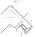
- FIG 4 is a slightly modified frame profile 1 'in an enlarged view shown.
- the frame profile 1 ' has an outer anchoring groove 3 and an inner one Anchoring groove 5 for appropriate seals and is through a reinforcement tube 8 particularly stiff.
- In the front area is the frame profile 1 'mitered.
- the frame profile 1 ' When joining two frame profiles 1 ' the frame profile 1 'shortened by the welding allowance s in length.
- With the arrow F is the force when heating the frame profile 1 'by pressing on the Welding mirror 6 and later shown when joining two frame profiles 1 '.
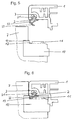
- FIGS. 5 to 9 show part of a device for carrying out the invention of the method described above.
- the device for welding two frame profiles 1 has for each frame profile 1 at least one receptacle 7 with a movable slide is provided.
- the slide 10 has a bottom surface 18 and is in the receptacle 7 slidably supported by guide profiles.
- 10 screws 14 fixed to the receptacle 7 to guide the slide connected so that the slide 10 through elongated holes 15 formed in the longitudinal direction is movable.
- the slide 10 is provided with a front wall 11, which ends with the front of the slide 10.
- the front wall 11 runs curved towards the bottom surface 18 obliquely downwards.
- a side wall 13 which is at right angles to the bottom surface 18 is arranged.
- a recess 12 is provided between the side wall 13 and the front wall 11 .
- the seal 2 is before insertion into the Recording 7 in the spread state, so that a sealing lip 23 from the frame profile 1 protrudes.
- the seal has 2 a fastening foot 21, which is designed as a compressible hollow profile is.
- the mounting foot 21 is through two lateral legs in an anchoring groove held. So that the seal 2 the restoring forces over a long Can hold time, the seal is provided with a cavity 22 which between the mounting foot 21 and the sealing lip 23 is formed.
- the frame profile 1 is on the Pad 7 and the slide 10 placed, as shown in Figure 6.
- the Cavity 22 compressed and the sealing lip 23 lies on the bottom surface 18 of the slide 10.
- the sealing lip 23 is inclined through the extending region of the front wall 11 compressed even more.
- the foremost tip of the seal 2 protrudes into the recess 12 so that the front wall 11 and the sealing tip in the recess 12 essentially a surface form.
- the seal 2 is also on the side wall 13 of the slide 10, so that a lateral bending of the seal 2 is prevented.
- Figure 6 is also with dashed lines with an alternative embodiment of the slide 10 elongated front wall 11 shown, in which the front wall 11 up to the Frame profile 1 is introduced.
- the slide 10 is biased in the holder 7 by a compression spring 16. At Overcoming the spring force, the slide 10 is moved backwards into that shown in FIG End position pressed.
- a frame profile is in the receptacle 7 1 placed so that the miter surface of the frame profile 1 with the front of Slider 10 completes. Then between two each in a holder 7 recorded frame profiles 1 introduced a welding mirror 6, the Miter surface of each frame profile 1 heated. By liquefying the plastic material the frame profile 1 is already partially in the direction when heated of the welding mirror 6 shifted. However, the seal 2 does not melt and will shifted by the distance in the frame profile 1 by which the frame profile 1 is moved to the welding mirror 6.
- the welding mirror 6 is removed to join the two frame profiles 1 and the two frame profiles 1 pressed together.
- the frame profiles 1 shortened by the welding allowance.
- the compression of the seal 2 in essentially distributed over the length of the slide 10, being through the front wall 11 ensures that the front region of the seal 2 with the miter surface completes.
- the slide 10 can be a Have adhesive surface to the seal 2 by frictional forces on the adhesive surface to move relatively in the frame profile 1. Furthermore, the slide 10 be designed telescopically, the displacement path in the area of the miter surface is larger than in an area away from the miter surface.
- other seals with two or more sealing lips are provided. The recording according to the invention was only described for the outer seal 2, but can also for the inner Seal 4 are used.
Landscapes
- Engineering & Computer Science (AREA)
- Mechanical Engineering (AREA)
- Lining Or Joining Of Plastics Or The Like (AREA)
Abstract
Description
- Fig. 1
- einen ersten Verfahrensschritt des erfindungsgemäßen Verfahrens, bei dem Rahmenprofile aufgeheizt werden;
- Fig. 2
- einen zweiten Verfahrensschritt am Anfang des Zusammenfügens der zwei Rahmenprofile;
- Fig. 3
- die zusammengefügten Rahmenprofile nach Abschluß des Verfahrens;
- Fig. 4
- eine vergrößerte Draufsicht auf zwei Rahmenprofile vor dem Zusammenfügen;
- Fig. 5
- eine Vorderansicht auf die Gehrungsfläche des Rahmenprofils vor dessen Auflegen auf die Aufnahme der erfindungsgemäßen Vorrichtung;
- Fig. 6
- eine Vorderansicht der erfindungsgemäßen Vorrichtung mit eingefügtem Rahmenprofil;
- Fig. 7
- eine perspektivische Ansicht einer Aufnahme einer erfindungsgemäßen Vorrichtung;
- Fig. 8
- eine Draufsicht auf die Aufnahme nach Figur 7 mit ausgefahrenem Schieber, und
- Fig. 9
- eine Draufsicht auf die Aufnahme nach Figur 7 mit eingefahrenem Schieber.
Claims (14)
- Verfahren zum Verschweißen von auf Gehrung geschnittenen Rahmenprofilen (1) aus Kunststoff mit eingezogenen, über die gesamte Profillänge sich erstreckenden, aus einem Befestigungsfuß (21) und mindestens einer Dichtlippe (23) bestehenden Dichtungen aus elastischem Material, dessen Schmelzpunkt höher liegt als der des Materials des Rahmenprofils (1), bei dem die Gehrungsflächen und die benachbarten Rahmenprofilbereiche durch eine Heizeinrichtung (6) auf die Verschweißungstemperatur aufgeheizt werden, die Heizeinrichtung (6) aus dem Bereich der Gehrungsflächen entfernt wird und die Gehrungsflächen der Rahmenprofile (1) zusammengepreßt und verschweißt werden, dadurch gekennzeichnet, daß die Dichtungen (2) im Bereich der Gehrungsflächen beim Zusammenfügen der Rahmenprofile (1) jeweils in Längsrichtung des Rahmenprofils (1) verschoben werden.
- Verfahren nach Anspruch 1, dadurch gekennzeichnet, daß die Dichtungen (2) im Bereich der Gehrungsflächen zusätzlich beim Aufheizen der Gehrungsflächen jeweils in Längsrichtung des Rahmenprofils (1) verschoben werden.
- Verfahren nach Anspruch 1 oder 2, dadurch gekennzeichnet, daß die Dichtungen (2) in einem zusammengedrückten Zustand verschoben werden.
- Verfahren nach einem der Ansprüche 1 bis 3, dadurch gekennzeichnet, daß die Dichtungen (2) an der Gehrungsfläche jeweils partiell komprimiert und auf das Rahmenprofil (1) gepreßt werden.
- Verfahren nach einem der Ansprüche 1 bis 4, dadurch gekennzeichnet, daß die Dichtungen (2) benachbart zu der Gehrungsfläche stärker verschoben werden als in einem weiter von der Gehrungsfläche entfernt liegenden Bereich.
- Verfahren nach einem der Ansprüche 1 bis 5, dadurch gekennzeichnet, daß die Dichtungen (2) im wesentlichen durch eine schräg zur Längsrichtung des Rahmenprofils (1) verlaufende Schieberfläche (11) verschoben werden.
- Verfahren nach einem der Ansprüche 1 bis 6, dadurch gekennzeichnet, daß die Dichtungen (2) mittels Klemmkräften verschoben werden.
- Vorrichtung zum Verschweißen von auf Gehrung geschnittenen Rahmenprofilen (1) aus Kunststoff mit eingezogenen Dichtungen (2) aus elastischem Material, insbesondere zur Durchführung des Verfahrens nach einem der vorhergehenden Ansprüche, mit zwei Aufnahmen (7), in denen jeweils ein Rahmenprofil (1) mit mindestens einer Dichtung (2) gehalten ist, und einer Heizeinrichtung (6) zum Aufheizen der Rahmenprofile (1) auf Schweißtemperatur, dadurch gekennzeichnet, daß an jeder Aufnahme (7) ein an einer Dichtung (2) angeordneter Schieber (10) vorgesehen ist, der in Längsrichtung des Rahmenprofils (1) bewegbar ist.
- Vorrichtung nach Anspruch 8, dadurch gekennzeichnet, daß die zur Gehrungsfläche gewandte Fläche des Schiebers (10) mit der Gehrungsfläche des Rahmenprofils (1) abschließt.
- Vorrichtung nach Anspruch 8 oder 9, dadurch gekennzeichnet, daß die Dichtung (2) auf einer Bodenfläche (18) des Schiebers (10) aufliegt und zumindest an einer Seitenwand (13) des Schiebers (10) anliegt.
- Vorrichtung nach einem der Ansprüche 8 bis 10, dadurch gekennzeichnet, daß der Schieber (10) zur Gehrungsfläche hin vorgespannt ist.
- Vorrichtung nach einem der Ansprüche 8 bis 11, dadurch gekennzeichnet, daß der Schieber (10) mehrstufig ausgebildet ist, derart, daß eine Schieberstufe benachbart zu der Gehrungsfläche einen längeren Verschiebeweg zurücklegt als eine von der Gehrungsfläche entfernte Schieberstufe.
- Vorrichtung nach einem der Ansprüche 8 bis 12, dadurch gekennzeichnet, daß zwischen dem Schieber (10) und der Aufnahme (7) sich einander gegenüber liegende Führungsprofile ausgebildet sind.
- Vorrichtung nach einem der Ansprüche 8 bis 13, dadurch gekennzeichnet, daß am Schieber (10) benachbart zu der Gehrungsfläche eine Vorderwand (11) vorgesehen ist, die zumindest teilweise an der Stirnfläche der Dichtung (2) anliegt.
Applications Claiming Priority (2)
| Application Number | Priority Date | Filing Date | Title |
|---|---|---|---|
| DE1999135076 DE19935076A1 (de) | 1999-07-28 | 1999-07-28 | Verfahren und Vorrichtung zum Verschweißen von auf Gehrung geschnittenen Rahmenprofilen aus Kunststoff |
| DE19935076 | 1999-07-28 |
Publications (2)
| Publication Number | Publication Date |
|---|---|
| EP1072392A1 true EP1072392A1 (de) | 2001-01-31 |
| EP1072392B1 EP1072392B1 (de) | 2003-11-12 |
Family
ID=7916120
Family Applications (1)
| Application Number | Title | Priority Date | Filing Date |
|---|---|---|---|
| EP20000115851 Expired - Lifetime EP1072392B1 (de) | 1999-07-28 | 2000-07-24 | Verfahren und Vorrichtung zum Verschweissen von auf Gehrung geschnittenen Rahmenprofilen aus Kunststoff |
Country Status (4)
| Country | Link |
|---|---|
| EP (1) | EP1072392B1 (de) |
| AT (1) | ATE254024T1 (de) |
| DE (2) | DE19935076A1 (de) |
| DK (1) | DK1072392T3 (de) |
Cited By (2)
| Publication number | Priority date | Publication date | Assignee | Title |
|---|---|---|---|---|
| EP2055462A2 (de) * | 2007-10-30 | 2009-05-06 | Semperit Aktiengesellschaft Holding | Verfahren zum Verschweißen von auf Gehrung geschnittenen Rahmenprofilen für Fenster, Türen oder dergleichen sowie Dichtungsstreifen zur Verwendung bei solchen Rahmenprofilen |
| DE102016104588A1 (de) | 2016-03-14 | 2017-09-14 | SCHÜCO International KG | Vorrichtung und Verfahren zum Verschweißen von auf Gehrung geschnittenen Rahmenprofilen aus Kunststoff |
Citations (4)
| Publication number | Priority date | Publication date | Assignee | Title |
|---|---|---|---|---|
| DE3405384C1 (de) * | 1984-02-15 | 1985-07-18 | SKS-Stakusit-Stahl-Kunststoff GmbH, 4100 Duisburg | Verfahren und Vorrichtung zum Verschweißen von zwei Kunststoffprofilen zur Rahmenecke eines Fenster- oder Türrahmens |
| EP0698719A1 (de) * | 1994-08-11 | 1996-02-28 | Hutchinson | Verfahren zur Herstellung von Tischlerei aus PVC, und Abdichtung dafür |
| EP0838324A2 (de) * | 1996-10-24 | 1998-04-29 | SCHÜCO International KG | Verfahren und Vorrichtung zum Verschweissen von auf Gehrung geschnittenen Rahmenprofilen aus Kunststoff mit eingezogenen Dichtungen |
| DE29710939U1 (de) * | 1997-06-24 | 1998-07-23 | Wilhelm Hollinger Maschinenbau | Vorrichtung zum Fixieren von Dichtungen |
-
1999
- 1999-07-28 DE DE1999135076 patent/DE19935076A1/de not_active Withdrawn
-
2000
- 2000-07-24 DE DE50004405T patent/DE50004405D1/de not_active Expired - Lifetime
- 2000-07-24 DK DK00115851T patent/DK1072392T3/da active
- 2000-07-24 AT AT00115851T patent/ATE254024T1/de not_active IP Right Cessation
- 2000-07-24 EP EP20000115851 patent/EP1072392B1/de not_active Expired - Lifetime
Patent Citations (4)
| Publication number | Priority date | Publication date | Assignee | Title |
|---|---|---|---|---|
| DE3405384C1 (de) * | 1984-02-15 | 1985-07-18 | SKS-Stakusit-Stahl-Kunststoff GmbH, 4100 Duisburg | Verfahren und Vorrichtung zum Verschweißen von zwei Kunststoffprofilen zur Rahmenecke eines Fenster- oder Türrahmens |
| EP0698719A1 (de) * | 1994-08-11 | 1996-02-28 | Hutchinson | Verfahren zur Herstellung von Tischlerei aus PVC, und Abdichtung dafür |
| EP0838324A2 (de) * | 1996-10-24 | 1998-04-29 | SCHÜCO International KG | Verfahren und Vorrichtung zum Verschweissen von auf Gehrung geschnittenen Rahmenprofilen aus Kunststoff mit eingezogenen Dichtungen |
| DE29710939U1 (de) * | 1997-06-24 | 1998-07-23 | Wilhelm Hollinger Maschinenbau | Vorrichtung zum Fixieren von Dichtungen |
Cited By (3)
| Publication number | Priority date | Publication date | Assignee | Title |
|---|---|---|---|---|
| EP2055462A2 (de) * | 2007-10-30 | 2009-05-06 | Semperit Aktiengesellschaft Holding | Verfahren zum Verschweißen von auf Gehrung geschnittenen Rahmenprofilen für Fenster, Türen oder dergleichen sowie Dichtungsstreifen zur Verwendung bei solchen Rahmenprofilen |
| DE102016104588A1 (de) | 2016-03-14 | 2017-09-14 | SCHÜCO International KG | Vorrichtung und Verfahren zum Verschweißen von auf Gehrung geschnittenen Rahmenprofilen aus Kunststoff |
| EP3219465A1 (de) | 2016-03-14 | 2017-09-20 | SCHÜCO International KG | Vorrichtung und verfahren zum verschweissen von auf gehrung geschnittenen rahmenprofilen aus kunststoff |
Also Published As
| Publication number | Publication date |
|---|---|
| DK1072392T3 (da) | 2004-03-08 |
| EP1072392B1 (de) | 2003-11-12 |
| DE50004405D1 (de) | 2003-12-18 |
| ATE254024T1 (de) | 2003-11-15 |
| DE19935076A1 (de) | 2001-02-01 |
Similar Documents
| Publication | Publication Date | Title |
|---|---|---|
| EP0838324B1 (de) | Verfahren und Vorrichtung zum Verschweissen von auf Gehrung geschnittenen Rahmenprofilen aus Kunststoff mit eingezogenen Dichtungen | |
| DE3039733A1 (de) | Verfahren zum stumpfverschweissen von thermoplastischen kunststoff-hohlprofilstaeben und vorrichtung zu dessen durchfuehrung | |
| DE60011948T2 (de) | Fensterrahmen und Verfahren zu seiner Herstellung | |
| DE102020126640A1 (de) | System mit einem Schwellenprofil, einem Blendrahmenprofil und einem Schwellenverbinder eines Fensters oder einer Tür | |
| DE60205994T2 (de) | Verfahren zum Reibrührverschweissen eines Randes mit einer Platte | |
| DE69808045T2 (de) | Verfahren und Vorrichtung zum thermischen Verbinden von Elementen zum Formen eines Rahmens | |
| EP1072392B1 (de) | Verfahren und Vorrichtung zum Verschweissen von auf Gehrung geschnittenen Rahmenprofilen aus Kunststoff | |
| DE29512613U1 (de) | Profiliertes Dichtungsband für Fenster, Türen, Deckel o.dgl. Bauteile | |
| DE2035308A1 (de) | Verfahren und Vorrichtung zur Her stellung von stumpfgeschweißten Rahmen aus Kunststoff oder Leichtmetall Profilschienen | |
| EP1179652B1 (de) | Eckverbinder | |
| DE19641312C2 (de) | Rahmen für Fenster, Türen, Fassaden oder dergleichen | |
| EP1889708A1 (de) | Verfahren und Vorrichtung zum Verschweissen von Kunststoffprofilen, insbesondere zur Bildung von Fenster- oder Türrahmen | |
| DE19753846A1 (de) | Schweißvorrichtung und Schweißverfahren für Hartkunststoffhohlprofile | |
| DE2316749C2 (de) | Außenform zur Verhinderung der Entstehung eines Schweißwulstes beim Stumpfschweißen von Kunststoffprofilen | |
| DE10146602C1 (de) | Verfahren zur Herstellung von Rahmen für Fenster oder Türen | |
| EP3219465B1 (de) | Vorrichtung und verfahren zum verschweissen von auf gehrung geschnittenen rahmenprofilen aus kunststoff | |
| DE19822292C2 (de) | Verfahren zur Verbindung von Profilholmen zwecks Bildung von Kunststoffrahmen und Verbindung von Profilholmen | |
| DE20016008U1 (de) | Vorrichtung zum Verschweißen von auf Gehrung geschnittenen Rahmenprofilen aus Kunststoff | |
| DE29609162U1 (de) | Strangförmige Dichtung | |
| DE102012102176A1 (de) | Stoßverbindung und Rahmenkonstruktion | |
| EP1103691B1 (de) | Eckverbinder für Falzverbreiterungen | |
| DE19612285A1 (de) | Verfahren zur Herstellung von Fensterrahmen aus Kunststoff | |
| DE2201656A1 (de) | Verfahren zum verschweissen von kunststoffprofilen und vorrichtung zur durchfuehrung des verfahrens | |
| DE102007018790A1 (de) | Verfahren und Vorrichtung zum Herstellen einer Verbindung zwischen Profilabschnitten und Dichtung, insbesondere zum Abdichten eines Schließelements eines Kraftfahrzeugs | |
| DE10102058A1 (de) | Vorrichtung zum Verschweißen von Kunststoffprofilen |
Legal Events
| Date | Code | Title | Description |
|---|---|---|---|
| PUAI | Public reference made under article 153(3) epc to a published international application that has entered the european phase |
Free format text: ORIGINAL CODE: 0009012 |
|
| AK | Designated contracting states |
Kind code of ref document: A1 Designated state(s): AT BE CH CY DE DK ES FI FR GB GR IE IT LI LU MC NL PT SE |
|
| AX | Request for extension of the european patent |
Free format text: AL;LT;LV;MK;RO;SI |
|
| 17P | Request for examination filed |
Effective date: 20010711 |
|
| 17Q | First examination report despatched |
Effective date: 20010829 |
|
| AKX | Designation fees paid |
Free format text: AT BE CH CY DE DK ES FI FR GB GR IE IT LI LU MC NL PT SE |
|
| GRAH | Despatch of communication of intention to grant a patent |
Free format text: ORIGINAL CODE: EPIDOS IGRA |
|
| GRAS | Grant fee paid |
Free format text: ORIGINAL CODE: EPIDOSNIGR3 |
|
| GRAA | (expected) grant |
Free format text: ORIGINAL CODE: 0009210 |
|
| AK | Designated contracting states |
Kind code of ref document: B1 Designated state(s): AT BE CH CY DE DK ES FI FR GB GR IE IT LI LU MC NL PT SE |
|
| PG25 | Lapsed in a contracting state [announced via postgrant information from national office to epo] |
Ref country code: IT Free format text: LAPSE BECAUSE OF FAILURE TO SUBMIT A TRANSLATION OF THE DESCRIPTION OR TO PAY THE FEE WITHIN THE PRESCRIBED TIME-LIMIT;WARNING: LAPSES OF ITALIAN PATENTS WITH EFFECTIVE DATE BEFORE 2007 MAY HAVE OCCURRED AT ANY TIME BEFORE 2007. THE CORRECT EFFECTIVE DATE MAY BE DIFFERENT FROM THE ONE RECORDED. Effective date: 20031112 Ref country code: FI Free format text: LAPSE BECAUSE OF FAILURE TO SUBMIT A TRANSLATION OF THE DESCRIPTION OR TO PAY THE FEE WITHIN THE PRESCRIBED TIME-LIMIT Effective date: 20031112 Ref country code: IE Free format text: LAPSE BECAUSE OF FAILURE TO SUBMIT A TRANSLATION OF THE DESCRIPTION OR TO PAY THE FEE WITHIN THE PRESCRIBED TIME-LIMIT Effective date: 20031112 Ref country code: CY Free format text: LAPSE BECAUSE OF FAILURE TO SUBMIT A TRANSLATION OF THE DESCRIPTION OR TO PAY THE FEE WITHIN THE PRESCRIBED TIME-LIMIT Effective date: 20031112 |
|
| REG | Reference to a national code |
Ref country code: GB Ref legal event code: FG4D Free format text: NOT ENGLISH |
|
| REG | Reference to a national code |
Ref country code: CH Ref legal event code: NV Representative=s name: ISLER & PEDRAZZINI AG Ref country code: CH Ref legal event code: EP |
|
| REF | Corresponds to: |
Ref document number: 50004405 Country of ref document: DE Date of ref document: 20031218 Kind code of ref document: P |
|
| GBT | Gb: translation of ep patent filed (gb section 77(6)(a)/1977) |
Effective date: 20031222 |
|
| REG | Reference to a national code |
Ref country code: IE Ref legal event code: FG4D Free format text: GERMAN |
|
| PG25 | Lapsed in a contracting state [announced via postgrant information from national office to epo] |
Ref country code: GR Free format text: LAPSE BECAUSE OF FAILURE TO SUBMIT A TRANSLATION OF THE DESCRIPTION OR TO PAY THE FEE WITHIN THE PRESCRIBED TIME-LIMIT Effective date: 20040212 |
|
| PG25 | Lapsed in a contracting state [announced via postgrant information from national office to epo] |
Ref country code: ES Free format text: LAPSE BECAUSE OF FAILURE TO SUBMIT A TRANSLATION OF THE DESCRIPTION OR TO PAY THE FEE WITHIN THE PRESCRIBED TIME-LIMIT Effective date: 20040223 |
|
| REG | Reference to a national code |
Ref country code: SE Ref legal event code: TRGR |
|
| REG | Reference to a national code |
Ref country code: DK Ref legal event code: T3 |
|
| REG | Reference to a national code |
Ref country code: IE Ref legal event code: FD4D |
|
| PG25 | Lapsed in a contracting state [announced via postgrant information from national office to epo] |
Ref country code: LU Free format text: LAPSE BECAUSE OF NON-PAYMENT OF DUE FEES Effective date: 20040724 |
|
| PG25 | Lapsed in a contracting state [announced via postgrant information from national office to epo] |
Ref country code: MC Free format text: LAPSE BECAUSE OF NON-PAYMENT OF DUE FEES Effective date: 20040731 |
|
| ET | Fr: translation filed | ||
| PLBE | No opposition filed within time limit |
Free format text: ORIGINAL CODE: 0009261 |
|
| STAA | Information on the status of an ep patent application or granted ep patent |
Free format text: STATUS: NO OPPOSITION FILED WITHIN TIME LIMIT |
|
| 26N | No opposition filed |
Effective date: 20040813 |
|
| PGFP | Annual fee paid to national office [announced via postgrant information from national office to epo] |
Ref country code: DK Payment date: 20050722 Year of fee payment: 6 Ref country code: SE Payment date: 20050722 Year of fee payment: 6 |
|
| PG25 | Lapsed in a contracting state [announced via postgrant information from national office to epo] |
Ref country code: SE Free format text: LAPSE BECAUSE OF NON-PAYMENT OF DUE FEES Effective date: 20060725 |
|
| PG25 | Lapsed in a contracting state [announced via postgrant information from national office to epo] |
Ref country code: DK Free format text: LAPSE BECAUSE OF NON-PAYMENT OF DUE FEES Effective date: 20060731 |
|
| REG | Reference to a national code |
Ref country code: DK Ref legal event code: EBP |
|
| EUG | Se: european patent has lapsed | ||
| REG | Reference to a national code |
Ref country code: CH Ref legal event code: PCAR Free format text: ISLER & PEDRAZZINI AG;POSTFACH 1772;8027 ZUERICH (CH) |
|
| PG25 | Lapsed in a contracting state [announced via postgrant information from national office to epo] |
Ref country code: PT Free format text: LAPSE BECAUSE OF NON-PAYMENT OF DUE FEES Effective date: 20040412 |
|
| PGFP | Annual fee paid to national office [announced via postgrant information from national office to epo] |
Ref country code: CH Payment date: 20080724 Year of fee payment: 9 |
|
| PGFP | Annual fee paid to national office [announced via postgrant information from national office to epo] |
Ref country code: AT Payment date: 20080722 Year of fee payment: 9 |
|
| PGFP | Annual fee paid to national office [announced via postgrant information from national office to epo] |
Ref country code: BE Payment date: 20080723 Year of fee payment: 9 |
|
| PGFP | Annual fee paid to national office [announced via postgrant information from national office to epo] |
Ref country code: FR Payment date: 20090720 Year of fee payment: 10 |
|
| PGFP | Annual fee paid to national office [announced via postgrant information from national office to epo] |
Ref country code: NL Payment date: 20090724 Year of fee payment: 10 Ref country code: GB Payment date: 20090724 Year of fee payment: 10 |
|
| BERE | Be: lapsed |
Owner name: *SCHUCO INTERNATIONAL K.G. Effective date: 20090731 |
|
| REG | Reference to a national code |
Ref country code: CH Ref legal event code: PL |
|
| PG25 | Lapsed in a contracting state [announced via postgrant information from national office to epo] |
Ref country code: LI Free format text: LAPSE BECAUSE OF NON-PAYMENT OF DUE FEES Effective date: 20090731 Ref country code: CH Free format text: LAPSE BECAUSE OF NON-PAYMENT OF DUE FEES Effective date: 20090731 |
|
| PG25 | Lapsed in a contracting state [announced via postgrant information from national office to epo] |
Ref country code: BE Free format text: LAPSE BECAUSE OF NON-PAYMENT OF DUE FEES Effective date: 20090731 Ref country code: AT Free format text: LAPSE BECAUSE OF NON-PAYMENT OF DUE FEES Effective date: 20090724 |
|
| REG | Reference to a national code |
Ref country code: NL Ref legal event code: V1 Effective date: 20110201 |
|
| GBPC | Gb: european patent ceased through non-payment of renewal fee |
Effective date: 20100724 |
|
| REG | Reference to a national code |
Ref country code: FR Ref legal event code: ST Effective date: 20110331 |
|
| PG25 | Lapsed in a contracting state [announced via postgrant information from national office to epo] |
Ref country code: FR Free format text: LAPSE BECAUSE OF NON-PAYMENT OF DUE FEES Effective date: 20100802 Ref country code: NL Free format text: LAPSE BECAUSE OF NON-PAYMENT OF DUE FEES Effective date: 20110201 |
|
| PG25 | Lapsed in a contracting state [announced via postgrant information from national office to epo] |
Ref country code: GB Free format text: LAPSE BECAUSE OF NON-PAYMENT OF DUE FEES Effective date: 20100724 |
|
| PGFP | Annual fee paid to national office [announced via postgrant information from national office to epo] |
Ref country code: DE Payment date: 20150810 Year of fee payment: 16 |
|
| REG | Reference to a national code |
Ref country code: DE Ref legal event code: R119 Ref document number: 50004405 Country of ref document: DE |
|
| PG25 | Lapsed in a contracting state [announced via postgrant information from national office to epo] |
Ref country code: DE Free format text: LAPSE BECAUSE OF NON-PAYMENT OF DUE FEES Effective date: 20170201 |