EP1071947B1 - Gel electrophoresis apparatus having cam-activated clamp and methods of use - Google Patents
Gel electrophoresis apparatus having cam-activated clamp and methods of use Download PDFInfo
- Publication number
- EP1071947B1 EP1071947B1 EP99917424A EP99917424A EP1071947B1 EP 1071947 B1 EP1071947 B1 EP 1071947B1 EP 99917424 A EP99917424 A EP 99917424A EP 99917424 A EP99917424 A EP 99917424A EP 1071947 B1 EP1071947 B1 EP 1071947B1
- Authority
- EP
- European Patent Office
- Prior art keywords
- cam
- mounting block
- container
- gel cassette
- gel
- Prior art date
- Legal status (The legal status is an assumption and is not a legal conclusion. Google has not performed a legal analysis and makes no representation as to the accuracy of the status listed.)
- Expired - Lifetime
Links
- 238000000034 method Methods 0.000 title claims abstract description 11
- 238000001502 gel electrophoresis Methods 0.000 title claims description 12
- 239000000872 buffer Substances 0.000 claims abstract description 83
- 238000001962 electrophoresis Methods 0.000 claims abstract description 32
- 238000003780 insertion Methods 0.000 claims description 5
- 230000037431 insertion Effects 0.000 claims description 5
- 230000008878 coupling Effects 0.000 claims 2
- 238000010168 coupling process Methods 0.000 claims 2
- 238000005859 coupling reaction Methods 0.000 claims 2
- 239000000499 gel Substances 0.000 description 64
- 239000007853 buffer solution Substances 0.000 description 22
- 238000002955 isolation Methods 0.000 description 5
- 238000001746 injection moulding Methods 0.000 description 4
- 239000000523 sample Substances 0.000 description 4
- 238000000926 separation method Methods 0.000 description 3
- 108020004414 DNA Proteins 0.000 description 2
- 239000004593 Epoxy Substances 0.000 description 2
- 238000005516 engineering process Methods 0.000 description 2
- 239000012530 fluid Substances 0.000 description 2
- 239000011521 glass Substances 0.000 description 2
- 239000000463 material Substances 0.000 description 2
- 229920003023 plastic Polymers 0.000 description 2
- 239000004033 plastic Substances 0.000 description 2
- AXAVXPMQTGXXJZ-UHFFFAOYSA-N 2-aminoacetic acid;2-amino-2-(hydroxymethyl)propane-1,3-diol Chemical compound NCC(O)=O.OCC(N)(CO)CO AXAVXPMQTGXXJZ-UHFFFAOYSA-N 0.000 description 1
- 229920002972 Acrylic fiber Polymers 0.000 description 1
- 102000053602 DNA Human genes 0.000 description 1
- 229920004943 Delrin® Polymers 0.000 description 1
- 239000004677 Nylon Substances 0.000 description 1
- 230000009471 action Effects 0.000 description 1
- 239000000853 adhesive Substances 0.000 description 1
- 230000001070 adhesive effect Effects 0.000 description 1
- 239000004020 conductor Substances 0.000 description 1
- 238000013461 design Methods 0.000 description 1
- 230000006872 improvement Effects 0.000 description 1
- 150000002500 ions Chemical class 0.000 description 1
- 230000001788 irregular Effects 0.000 description 1
- 230000007246 mechanism Effects 0.000 description 1
- 230000005012 migration Effects 0.000 description 1
- 238000013508 migration Methods 0.000 description 1
- 238000012986 modification Methods 0.000 description 1
- 230000004048 modification Effects 0.000 description 1
- 229920001778 nylon Polymers 0.000 description 1
- 230000002093 peripheral effect Effects 0.000 description 1
- 229920002401 polyacrylamide Polymers 0.000 description 1
- 102000004169 proteins and genes Human genes 0.000 description 1
- 108090000623 proteins and genes Proteins 0.000 description 1
- 229920002477 rna polymer Polymers 0.000 description 1
- 239000012723 sample buffer Substances 0.000 description 1
- 230000003068 static effect Effects 0.000 description 1
Images

Classifications
-
- G—PHYSICS
- G01—MEASURING; TESTING
- G01N—INVESTIGATING OR ANALYSING MATERIALS BY DETERMINING THEIR CHEMICAL OR PHYSICAL PROPERTIES
- G01N27/00—Investigating or analysing materials by the use of electric, electrochemical, or magnetic means
- G01N27/26—Investigating or analysing materials by the use of electric, electrochemical, or magnetic means by investigating electrochemical variables; by using electrolysis or electrophoresis
- G01N27/416—Systems
- G01N27/447—Systems using electrophoresis
- G01N27/44704—Details; Accessories
-
- Y—GENERAL TAGGING OF NEW TECHNOLOGICAL DEVELOPMENTS; GENERAL TAGGING OF CROSS-SECTIONAL TECHNOLOGIES SPANNING OVER SEVERAL SECTIONS OF THE IPC; TECHNICAL SUBJECTS COVERED BY FORMER USPC CROSS-REFERENCE ART COLLECTIONS [XRACs] AND DIGESTS
- Y10—TECHNICAL SUBJECTS COVERED BY FORMER USPC
- Y10T—TECHNICAL SUBJECTS COVERED BY FORMER US CLASSIFICATION
- Y10T74/00—Machine element or mechanism
- Y10T74/18—Mechanical movements
- Y10T74/18888—Reciprocating to or from oscillating
- Y10T74/1892—Lever and slide
- Y10T74/1896—Cam connections
Definitions
- This invention relates to apparatus for performing electrophoresis. More particularly, this invention relates to a novel cam device for clamping gel cassettes in a gel electrophoresis system.
- Gel electrophoresis is commonly used to separate by molecular size biological molecules, such as deoxyribonucleic acid ("DNA”), ribonucleic acid (“RNA”) and proteins.
- DNA deoxyribonucleic acid
- RNA ribonucleic acid
- a polymeric gel such as polyacrylamide
- the tube or plates are then placed in a container along with anode and cathode elements at the top and bottom of the gel.
- Sample wells formed in the top of the gel are first filled with buffer solutions. Molecule samples prepared in a sample buffer that may contain a tracking dye are then placed in the wells.
- Electrophoretic buffer solutions containing conductive ions are added to the container to make electrical contact between the gel, the samples in the wells and the anode and cathode elements. A voltage is then applied across the gel, which causes the sample molecules and any tracking dye to migrate toward the bottom of the gel, and separate into bands whose migration distance depends on molecular size.
- Previously known commercial gel electrophoresis systems such as the XCell II Mini-CellTM manufactured by Novel Experimental Technology, Incorporated, San Diego, California (“NOVEX”), include a container for receiving a first buffer solution and a buffer core assembly that comprises a pair of gel cassettes affixed to front and back sides of a U-shaped buffer core.
- the space defined by the upraised side members of the buffer core and the end faces of the gel cassettes forms an upper buffer chamber.
- the buffer core assembly is immersed in the first buffer solution in the container, and a second buffer solution is added to the upper buffer chamber.
- the first and second buffer solutions must be isolated from one another.
- prior art electrophoresis systems use various methods to hold the gel cassettes in contact with the buffer core and secure the buffer core assembly in the container.
- Previously known electrophoresis systems commonly use a buffer core subassembly containing clamps or latches that secure the gel cassettes to the buffer core. Once the cassettes are secured, the buffer core subassembly must then be loaded in the container prior to electrophoretic separation.
- the SE 200 Series Mini-Gel System manufactured by Hoefer Pharmacia, San Francisco, California includes a buffer core subassembly that uses four spring clamps to secure a pair of gel cassettes to a buffer core.
- the Mini-PROTEAN II Electrophoresis Cell manufactured by Bio-Rad, Hercules, California (“Bio-Rad”), includes a buffer core subassembly that uses latches to secure gel cassettes to a buffer core.
- the Ready-Gel Cell manufactured by Bio-Rad and described in U.S. Pat. No. 5,632,877 includes a buffer core subassembly having a pair of cams that secure gel cassettes to a buffer core.
- the XCELL II Mini-CellTM uses two wedge blocks inserted in the electrophoresis container to secure the gel cassettes against the buffer core.
- the wedge blocks must be carefully inserted to obtain proper clamping action. For example, if the wedge blocks are not properly inserted, they may slip relative to one another, and may release pressure on the gel cassettes and degrade isolation between the first and second buffer solutions. Further, the wedge blocks provide a clamping force that varies depending on the amount of force used to insert the wedge blocks into the container. If too much force is applied, the components of the electrophoresis system may become over-stressed and may eventually fracture. If too little force is applied, the gel cassettes may not be securely held in contact against the buffer core.
- a cam-activated device that includes a cam arm assembly having a pair of spaced-apart cam arms pivotally coupled to a mounting block.
- the cam device is adapted for insertion into an electrophoresis container and is positioned adjacent a buffer core assembly that includes first and second gel cassettes disposed on opposite sides of a buffer core body.
- a cam is attached to the cam arms and has a curved end that slidingly engages the back wall of the electrophoresis container as the cam arm assembly is pivoted forward toward the front wall of the container. As the curved end engages the back wall of the container, the mounting block applies uniform pressure to the first gel cassette and the buffer core body.
- the second gel cassette abuts fixed vertical ridges formed in the side walls of the container, thereby securing the mounting block against the buffer core assembly and clamping the gel cassettes to the buffer core body.
- Flat surfaces provided on forward-facing edges of the cam arms contact a back surface of the mounting block, thereby providing a positive stop.
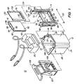
- FIG 1. An electrophoresis system including an exemplary embodiment of the present invention is shown in FIG 1.
- the system 10 comprises container 12, buffer core body 14, gel cassettes 16 and 18, lid 20,_and cam device 22, constructed in accordance with the principles of the present invention.
- Buffer core body 14 and gel cassettes 16 and 18 collectively form buffer core assembly 24.
- Container 12 includes front wall 26, side walls 28 and 30, back wall 32 and closed bottom 34. Container 12 is open at the top for receiving a first electrophoresis buffer solution (not shown). Located on opposite inner surfaces of side walls 28 and 30 and spaced away from the front wall 26 of container 12 are wall recesses 44 and 46. Wall recesses 44 and 46 are aligned with each other to receive buffer core assembly 24 and are integrally formed with side walls 28 and 30, respectively. Each of the wall recesses has a cross-section of an irregular C-channel when viewed from the top of container 12.
- Wall recesses 44 and 46 are sized to accommodate the lateral width 53 of buffer core assembly 24 without significant lateral movement.
- the width of wall recesses 44 and 46 is slightly greater than width 53 to facilitate the placement of buffer core assembly 24 in container 12.
- Vertical ridges 48 and 50 extend along the height of container 12 where wall recesses 44 and 46 open to inner side walls 28 and 30 toward front wall 26 of container 12. Vertical ridges 48 and 50 abut buffer core assembly 24 in its installed position, as will be discussed in further detail below.
- Buffer core assembly 24 includes gel cassettes 16 and 18, which are placed on front side 54 and back side 56 of buffer core body 14 to form a portion of the sides of upper buffer chamber 52.
- Upper buffer chamber 52 holds a second electrically chargeable buffer solution.
- upper buffer chamber 52 often is referred to as the anode chamber or the cathode chamber, depending on the polarity of the electric charge applied to the buffer solution contained in upper buffer chamber 52.
- Buffer core body 14 generally is U-shaped, and includes spaced-apart upraised side members 58 and 60, base 62 and beam 64. Beam 64 provides support for and connects side members 58 and 60, and is positioned approximately halfway between the front and back sides of buffer core body 14. Flanges 66 and 68 are located at the top portions of side members 58 and 60, respectively. Buffer core body 14 also has front inset 70 and rear inset 72.
- Gel cassettes 16 and 18 are positioned on each of the front and rear sides of buffer core body 14 in a sandwiched fashion. Gel cassettes 16 and 18 have a front surface 80 and a back surface 82. Each gel cassette includes a pair of thin wall plates that are commonly referred to as the divider or divider plate 84 and the retainer or retainer plate 86. Retainer plate 86 is slightly shorter in height than divider plate 84.
- Divider plate 84 is affixed to a peripheral ridge (not shown) along the lateral sides and the bottom periphery of retainer plate 86 to define an internal gel compartment 88 for holding an electrophoresis gel (not shown).
- Gel compartment 88 has a comb opening 90 at the top portion of the cassette for receiving a sample that is to be electrophoretically separated.
- an opening 92 Located along the lower portion of divider plate 84 and traversing the width of each of gel cassettes 16 and 18 is an opening 92 that opens gel compartment 88 to the exterior of the cassette.
- Gel cassettes suitable for the present application are known in the art. In a typical gel cassette, the gel is pre-filled within the internal gel compartment for ease of handling.
- the comb opening 90 is closed with a comb (not shown) and opening 92 is masked closed with a removable tape (not shown).
- An example of the gel cassettes that are suitable for this application are the 12% Tris-glycine gels sold by Novel Experimental Technology, Incorporated of San Diego, California, Catalog No. EC6005. Gel cassettes of similar types are also commercially available from other sources.
- Gel cassettes 16 and 18 are positioned adjacent each of front side 54 and back side 56 of buffer core body 14 in a sandwiched fashion to define upper buffer chamber 52 for receiving the second buffer solution (not shown).
- the second buffer solution is isolated from the first buffer solution in container 12.
- the portion of container 12 that contains the first buffer solution is often referred to as the lower buffer chamber, as distinguished from upper buffer chamber 52.
- Both the front and the rear surfaces of buffer core body 14 are provided with grooves 94 and 96 for fitting and holding resilient strips 98 and 100, respectively, as a seal between the gel cassettes and buffer core body 14.
- the seal ensures isolation of the second buffer solution in upper buffer chamber 52 from the first buffer solution in container 12, and provides a cushion to reduce excess stress along the force bearing surfaces of the cassettes when they are held against buffer core body 14.
- the comb (not shown) and the tape (not shown) are removed prior to the use of gel cassettes 16 and 18, the comb (not shown) and the tape (not shown) are removed.
- the sample to be analyzed is introduced into the gel compartment 88 through the comb opening 90 by appropriate means such as a pipette.
- Buffer core assembly 24 is then slidably inserted into wall recesses 44 and 46 from the top of container 12 to rest on risers 104 (one of which is shown in FIG. 5) inside container 12. Risers 104 elevate buffer core assembly 24 to permit the first buffer solution to pass below and surround the front and back sides of buffer core assembly 24.
- Buffer core assembly 24 is then moved toward front wall 26 of container 12 such that side ridges 102 of gel cassette 18 are aligned coincidentally with and bear upon vertical ridges 48 and 50.
- a single cassette can be installed on one side of buffer core body 14, and a blank or a plate member can be placed on the other side to achieve similar performance and results with assured consistency and uniformity.
- Cam device 22 comprises mounting block 106 and cam arm assembly 128.
- Mounting block 106 includes a generally square or rectangular front panel 108 and contact surfaces 110 and 112 on the lateral sides of front panel 108.
- a plurality of upraised push tabs 115 are provided to bear upon bottom edge 99 of divider plate 84 (shown in FIG. 1).
- a pair of spaced apart parallel side panels 116 and 118 are provided to enhance structural integrity of mounting block 106 and to support it in an erect position.
- Side panels 116 and 118 substantially align with contact surfaces 110 and 112, respectively.
- Bases 124 and 126 of side panels 116 and 118 extend from back surface 142 of front panel 108.
- Inclined edges 120 and 122 extend from the top of contact surfaces 110 and 112 to bases 124 and 126.
- Cam arm assembly 128 includes cam arms 130 and 132, cam 134, top plate 136, grip 138 and axle 140.
- Cam arms 130 and 132 are affixed to sides of cam 134 by suitable fasteners, for example, screws 146, or suitable adhesive, such as epoxy.
- cam 134 also is affixed to cam arms 130 and 132 at ends 150 and 152.
- Cam 134 includes edge 154 and curved end 148 extending between cam arms 130 and 132.
- top plate 136 and grip 138 form a handle used to pivot cam arm assembly 128 relative to mounting block 106.
- Top plate 136 is attached by suitable fasteners to top ends 156 and 158 of cam arms 130 and 132, respectively.
- Oval-shaped recess 190 provides clearance for tab 188 of container 12 (shown in FIG. 1).
- Grip 138 is attached to the top surface of top plate 136 or alternatively may be attached to cam arms 130 and 132.
- axle 140 extends through holes (not shown) near curved ends 164 and 166, and terminates at tips 172 and 174 that extend beyond outer surfaces 168 and 170 of cam arms 130 and 132, respectively.
- Axle 140 is securely attached to cam arms 130 and 132 by suitable means, for example, epoxy.
- Axle 140 freely pivots in holes 176 and 178.
- Mounting block 106 and cam arm assembly 128 can be fabricated from a number of materials by a variety of methods. In the embodiments described herein, and by way of example only, mounting block 106 is formed by injection molding of acrylic plastic, and cam arm assembly 128 may be constructed from delrin, or other suitable inert plastic material such as nylon. Alternatively, cam arm assembly 128 may be formed as a single unit by injection molding.
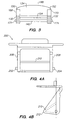
- FIGS. 4A and 4B show an alternative embodiment of cam arm assembly 200.
- Cylindrical side tabs 202 and 204 are integral with and extend from cam arms 206 and 208, respectively, and are disposed to pivot in holes 176 and 178 of mounting block 106.
- V-shaped cam 210 is formed integrally with cam arms 206 and 208.
- Cam 210 includes curved end 212 (similar to curved end 148 in FIG. 3) extending between cam arms 206 and 208.
- Cam arm assembly 200 may be fabricated as a single unit, for example by injection molding.
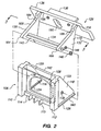
- FIG. 5 illustrates cam device 22 inserted into container 12 with cam arm assembly 128 disposed in an open position toward back wall 32 of container 12.
- mounting block 106 is disposed adjacent gel cassette 16 at back side 56 of buffer core assembly 24.
- Base 124 of side panel 116 includes tapered bottom edge 180 that rests on riser 104.
- base 126 of side panel 118 similarly includes tapered bottom edge 160 (shown in FIG. 2) that rests on a riser disposed near side wall 30 of container 12.
- mounting block 106 upon initial insertion into container 12, mounting block 106 is positioned so that top portion 182 of contact surfaces 110 and 112 (not shown) are disposed away from side ridges 102 of gel cassette 16.
- FIG. 6 illustrates cam device 22 with cam arm assembly 128 in a closed position.
- cam arm assembly 128 is shown rotated forward toward front wall 26 of container 12.
- curved end 148 bears against back wall 32, causing mounting block 106 to pivot forward on tapered bottom edges 160 and 180 toward gel cassette 16.
- contact surfaces 110 and 112 align with and bear upon side ridges 102 of gel cassette 16, pressing gel cassette 16 against buffer core body 14.
- Buffer core body 14 in turn bears upon gel cassette 18, pressing side ridges 102 of gel cassette 18 against vertical ridges 48 and 50 (not shown).
- cam 134 therefore goes "over center” at a point where curved end 148 exceeds the point of maximum pressure against back wall 32, thus locking cam device 22 in position. Because force would be required to return cam arm assembly 128 backward past plane (i.e., returning curved end 148 below dashed line 214), the over-center cam 134 secures mounting block 106 against gel cassette 16.
- flat portions 184 and 186 (not shown) of cam arms 130 and 132, respectively, contact back surface 142 of front panel 108, providing a positive stop that prevents cam arm assembly 128 from further forward movement.
- the resiliency of the strips 98 and 100 also provides a means of resistance against the bearing force of mounting block 106 such that a static balance is maintained among buffer core body 14, gel cassettes 16 and 18, mounting block 106, cam arm assembly 128 and back wall 32 of container 12, thereby securing them in container 12.
- Cam device 22 provides a consistent and reproducible clamping force to buffer core assembly 24.
- cam arm assembly 128 is pivotally coupled to mounting block 106, mounting block 106 cannot slip relative to cam arm assembly 128, and thereby inadvertently release pressure on buffer core assembly 24.
- cam 134 goes “over center,” cam device 22 is locked in position and applies a consistent and reproducible clamping force to buffer core assembly 24 that does not depend upon the amount of force applied to top plate 136 and grip 138.
- buffer core assembly 24 and cam device 22 are first secured within container 12 in the manner as described above.
- a first buffer solution is dispensed into the upper buffer chamber 52 above the comb openings 90 of gel cassettes 16 and 18 to establish fluid contact with the gel in the gel compartments.
- a second buffer solution is then introduced into container 12 until its level is approximately that of beam 64.
- Lid 20 is then positioned above the front portion of container 12, the conductor cables are attached to a power supply system or charging means (not shown) and electrophoresis commences .
- cam arm assembly 128 may be fabricated as a single unit by injection molding or other similar technique. Accordingly, it is not intended that the invention be limited, except as by the appended claims.
Landscapes
- Health & Medical Sciences (AREA)
- Life Sciences & Earth Sciences (AREA)
- Molecular Biology (AREA)
- Chemical & Material Sciences (AREA)
- Chemical Kinetics & Catalysis (AREA)
- Electrochemistry (AREA)
- Physics & Mathematics (AREA)
- Analytical Chemistry (AREA)
- Biochemistry (AREA)
- General Health & Medical Sciences (AREA)
- General Physics & Mathematics (AREA)
- Immunology (AREA)
- Pathology (AREA)
- Investigating Or Analysing Biological Materials (AREA)
- Apparatus Associated With Microorganisms And Enzymes (AREA)
- Peptides Or Proteins (AREA)
- Eye Examination Apparatus (AREA)
- Reciprocating Pumps (AREA)
Applications Claiming Priority (3)
| Application Number | Priority Date | Filing Date | Title |
|---|---|---|---|
| US59604 | 1998-04-13 | ||
| US09/059,604 US6001233A (en) | 1998-04-13 | 1998-04-13 | Gel electrophoresis apparatus having CAM-activated clamp and methods of use |
| PCT/US1999/007976 WO1999053305A1 (en) | 1998-04-13 | 1999-04-12 | Gel electrophoresis apparatus having cam-activated clamp and methods of use |
Publications (2)
| Publication Number | Publication Date |
|---|---|
| EP1071947A1 EP1071947A1 (en) | 2001-01-31 |
| EP1071947B1 true EP1071947B1 (en) | 2005-12-21 |
Family
ID=22024054
Family Applications (1)
| Application Number | Title | Priority Date | Filing Date |
|---|---|---|---|
| EP99917424A Expired - Lifetime EP1071947B1 (en) | 1998-04-13 | 1999-04-12 | Gel electrophoresis apparatus having cam-activated clamp and methods of use |
Country Status (9)
| Country | Link |
|---|---|
| US (1) | US6001233A (enExample) |
| EP (1) | EP1071947B1 (enExample) |
| JP (1) | JP4393703B2 (enExample) |
| AT (1) | ATE313791T1 (enExample) |
| AU (1) | AU3555199A (enExample) |
| CA (1) | CA2328212C (enExample) |
| DE (1) | DE69929044T2 (enExample) |
| DK (1) | DK1071947T3 (enExample) |
| WO (1) | WO1999053305A1 (enExample) |
Families Citing this family (28)
| Publication number | Priority date | Publication date | Assignee | Title |
|---|---|---|---|---|
| DE19854096A1 (de) * | 1998-11-24 | 2000-05-25 | Merck Patent Gmbh | Anschlußträger für plattenförmige Mikrokomponenten |
| US6162342A (en) * | 1999-02-12 | 2000-12-19 | Bio-Rad Laboratories, Inc. | Rapid assembly casting system for slab gels |
| US7517442B1 (en) | 1999-08-09 | 2009-04-14 | Life Technologies Corporation | Facile method and apparatus for the analysis of biological macromolecules in two dimensions using common and familiar electrophoresis formats |
| US6436262B1 (en) * | 2000-04-24 | 2002-08-20 | Bio-Rad Laboratories, Inc. | Compact cell clamp for slab gel plate assembly |
| US6686188B2 (en) | 2000-05-26 | 2004-02-03 | Amersham Plc | Polynucleotide encoding a human myosin-like polypeptide expressed predominantly in heart and muscle |
| US6656700B2 (en) | 2000-05-26 | 2003-12-02 | Amersham Plc | Isoforms of human pregnancy-associated protein-E |
| JP4236938B2 (ja) * | 2001-05-10 | 2009-03-11 | インビトロジェン コーポレイション | 予め注型された水和可能分離媒体を電気泳動するための方法および装置 |
| US7601251B2 (en) * | 2001-05-10 | 2009-10-13 | Life Technologies Corporation | Methods and apparatus for low resistance electrophoresis of prior-cast, hydratable separation media |
| US20040078837A1 (en) * | 2001-08-02 | 2004-04-22 | Shannon Mark E. | Four human zinc-finger-containing proteins: MDZ3, MDZ4, MDZ7 and MDZ12 |
| US7749367B2 (en) * | 2003-03-05 | 2010-07-06 | Deming Zhou | Vertical slab gel electrophoresis cell and method therefor |
| US20050103628A1 (en) * | 2003-09-22 | 2005-05-19 | Jackson Thomas R. | Apparatus for concurrent electrophoresis in a plurality of gels |
| US7250097B2 (en) * | 2004-04-26 | 2007-07-31 | The United States Of America, Department Of Health And Human Services | Device for sequential protein transfer from a gel |
| EP1872117B1 (en) * | 2005-04-15 | 2017-03-29 | Life Technologies Corporation | Expanding cam lock for sealing slab gels in an electrophoresis apparatus |
| WO2006113694A2 (en) * | 2005-04-15 | 2006-10-26 | Invitrogen Corporation | Gel cassette adapter |
| CN2824030Y (zh) * | 2005-09-29 | 2006-10-04 | 北京百晶生物技术有限公司 | 一次装夹胶室的垂直电泳仪 |
| USD794823S1 (en) * | 2010-08-24 | 2017-08-15 | Life Technologies Corporation | Electrophoresis tank with a base and cassette inserted in |
| JP2014219218A (ja) * | 2013-05-01 | 2014-11-20 | システム・インスツルメンツ株式会社 | 電気泳動用ゲルホルダおよび電気泳動方法 |
| KR101470733B1 (ko) * | 2013-05-14 | 2014-12-08 | 고창욱 | 수직형 단백질 전기영동장치 시스템에 사용되는 누수방지 젤캐스팅장치 |
| US10359396B2 (en) | 2015-11-13 | 2019-07-23 | Life Technologies Corporation | Preparation of electrophoresis gels, and related devices, systems, and methods |
| USD859688S1 (en) | 2015-11-13 | 2019-09-10 | Life Technologies Corporation | Electrophoresis slab gel sample loading guide |
| USD792603S1 (en) | 2015-11-13 | 2017-07-18 | Life Technologies Corporation | Rig for electrophoresis gel casting |
| USD849963S1 (en) | 2015-11-13 | 2019-05-28 | Life Technologies Corporation | Electrophoresis gel cassette |
| USD816865S1 (en) | 2015-11-13 | 2018-05-01 | Life Technologies Corporation | Cassette support base for electrophoresis gel casting |
| USD851779S1 (en) | 2015-11-13 | 2019-06-18 | Life Technologies Corporation | Electrophoresis cassette with sample loading guide |
| USD856528S1 (en) * | 2015-11-13 | 2019-08-13 | Life Technologies Corporation | Cassette clamp for electrophoresis gel casting |
| WO2022015661A2 (en) * | 2020-07-13 | 2022-01-20 | Life Technologies Corporation | Electrophoresis & electrotransfer devices, systems, & methods |
| USD975873S1 (en) | 2020-07-13 | 2023-01-17 | Life Technologies Corporation | Electrophoresis and electrotransfer device |
| KR102642983B1 (ko) * | 2021-06-16 | 2024-03-04 | 강규광 | 연구용 전기 영동장치 |
Family Cites Families (13)
| Publication number | Priority date | Publication date | Assignee | Title |
|---|---|---|---|---|
| US344713A (en) * | 1886-06-29 | Clamp | ||
| CH293210A (it) * | 1951-09-12 | 1953-09-15 | Uffireco S A | Morsetto a mano senza vite di serraggio. |
| USD261609S (en) | 1979-05-02 | 1981-11-03 | Pierre Roux | Vise |
| US4399989A (en) * | 1981-05-13 | 1983-08-23 | Baillie Robert A | Safe grip slicer for bagels, rolls, muffins and the like |
| JPS62127662A (ja) * | 1985-11-29 | 1987-06-09 | Dai Ichi Pure Chem Co Ltd | タテ・スラブ型電気泳動装置 |
| US4929329A (en) * | 1987-04-27 | 1990-05-29 | Eg&G, Inc. | Electrophoresis cassette system with apparatus and method for filling same |
| US4872358A (en) * | 1987-06-11 | 1989-10-10 | U.S. Philips Corporation | Driving mechanism having a pressure member |
| US4884792A (en) * | 1988-08-11 | 1989-12-05 | Lake Center Industries A Division Of Guy F. Atkinson Company | Clamp |
| US5112470A (en) * | 1990-12-07 | 1992-05-12 | Stratagene | Electrophoresis apparatus |
| JPH0624768A (ja) * | 1992-07-01 | 1994-02-01 | Nippon Electric Glass Co Ltd | 天然大理石様結晶化ガラス物品及びその製造方法 |
| US5792332A (en) * | 1995-12-21 | 1998-08-11 | Hoefer Pharmacia Biotech, Inc. | Safe electrophoresis unit |
| US5632877A (en) * | 1996-05-20 | 1997-05-27 | Bio-Rad Laboratories, Inc. | Rapid assembly electrophoresis cell for slab gels |
| US5888369A (en) * | 1997-03-28 | 1999-03-30 | Novel Experimental Technology | Apparatus for conducting electrophoresis experiments |
-
1998
- 1998-04-13 US US09/059,604 patent/US6001233A/en not_active Expired - Lifetime
-
1999
- 1999-04-12 CA CA002328212A patent/CA2328212C/en not_active Expired - Fee Related
- 1999-04-12 DK DK99917424T patent/DK1071947T3/da active
- 1999-04-12 DE DE69929044T patent/DE69929044T2/de not_active Expired - Lifetime
- 1999-04-12 AT AT99917424T patent/ATE313791T1/de not_active IP Right Cessation
- 1999-04-12 JP JP2000543821A patent/JP4393703B2/ja not_active Expired - Lifetime
- 1999-04-12 EP EP99917424A patent/EP1071947B1/en not_active Expired - Lifetime
- 1999-04-12 AU AU35551/99A patent/AU3555199A/en not_active Abandoned
- 1999-04-12 WO PCT/US1999/007976 patent/WO1999053305A1/en not_active Ceased
Also Published As
| Publication number | Publication date |
|---|---|
| DK1071947T3 (da) | 2006-03-06 |
| CA2328212A1 (en) | 1999-10-21 |
| AU3555199A (en) | 1999-11-01 |
| JP2002511584A (ja) | 2002-04-16 |
| CA2328212C (en) | 2007-08-07 |
| WO1999053305A1 (en) | 1999-10-21 |
| ATE313791T1 (de) | 2006-01-15 |
| JP4393703B2 (ja) | 2010-01-06 |
| EP1071947A1 (en) | 2001-01-31 |
| US6001233A (en) | 1999-12-14 |
| DE69929044T2 (de) | 2006-08-17 |
| DE69929044D1 (de) | 2006-01-26 |
Similar Documents
| Publication | Publication Date | Title |
|---|---|---|
| EP1071947B1 (en) | Gel electrophoresis apparatus having cam-activated clamp and methods of use | |
| US4574040A (en) | Apparatus for vertical gel electrophoresis | |
| US10352897B2 (en) | Expanding cam lock for sealing slab gels in an electrophoresis apparatus | |
| CA2124345C (en) | Gel electrophoresis sample applicator/retriever | |
| CA2148539C (en) | Electrophoresis slab gel enclosure for gradient gels | |
| US5284565A (en) | Sample well insert with wedge-shaped profile for ultra-thin slab gels in electrophoresis | |
| US6436262B1 (en) | Compact cell clamp for slab gel plate assembly | |
| US8034223B2 (en) | Methods and apparatus for low resistance electrophoresis of prior-cast, hydratable separation media | |
| US5209831A (en) | Bufferless electrophoresis system and method | |
| US20100059380A1 (en) | Apparatus for concurrent electrophoresis in a plurality of gels | |
| EP1032827A1 (en) | Gel casting and electrophoresis device | |
| US5164066A (en) | Electrophoresis cassette system with apparatus and method for filling same | |
| WO2000065336A9 (en) | Electrophoresis assembly and method of casting electrophoresis gels |
Legal Events
| Date | Code | Title | Description |
|---|---|---|---|
| PUAI | Public reference made under article 153(3) epc to a published international application that has entered the european phase |
Free format text: ORIGINAL CODE: 0009012 |
|
| 17P | Request for examination filed |
Effective date: 20001110 |
|
| AK | Designated contracting states |
Kind code of ref document: A1 Designated state(s): AT BE CH CY DE DK ES FI FR GB GR IE IT LI LU MC NL PT SE |
|
| RAP1 | Party data changed (applicant data changed or rights of an application transferred) |
Owner name: INVITROGEN CORPORATION |
|
| GRAP | Despatch of communication of intention to grant a patent |
Free format text: ORIGINAL CODE: EPIDOSNIGR1 |
|
| GRAS | Grant fee paid |
Free format text: ORIGINAL CODE: EPIDOSNIGR3 |
|
| GRAA | (expected) grant |
Free format text: ORIGINAL CODE: 0009210 |
|
| AK | Designated contracting states |
Kind code of ref document: B1 Designated state(s): AT BE CH CY DE DK ES FI FR GB GR IE IT LI LU MC NL PT SE |
|
| PG25 | Lapsed in a contracting state [announced via postgrant information from national office to epo] |
Ref country code: NL Free format text: LAPSE BECAUSE OF FAILURE TO SUBMIT A TRANSLATION OF THE DESCRIPTION OR TO PAY THE FEE WITHIN THE PRESCRIBED TIME-LIMIT Effective date: 20051221 Ref country code: IT Free format text: LAPSE BECAUSE OF FAILURE TO SUBMIT A TRANSLATION OF THE DESCRIPTION OR TO PAY THE FEE WITHIN THE PRESCRIBED TIME-LIMIT;WARNING: LAPSES OF ITALIAN PATENTS WITH EFFECTIVE DATE BEFORE 2007 MAY HAVE OCCURRED AT ANY TIME BEFORE 2007. THE CORRECT EFFECTIVE DATE MAY BE DIFFERENT FROM THE ONE RECORDED. Effective date: 20051221 Ref country code: FI Free format text: LAPSE BECAUSE OF FAILURE TO SUBMIT A TRANSLATION OF THE DESCRIPTION OR TO PAY THE FEE WITHIN THE PRESCRIBED TIME-LIMIT Effective date: 20051221 Ref country code: BE Free format text: LAPSE BECAUSE OF FAILURE TO SUBMIT A TRANSLATION OF THE DESCRIPTION OR TO PAY THE FEE WITHIN THE PRESCRIBED TIME-LIMIT Effective date: 20051221 Ref country code: AT Free format text: LAPSE BECAUSE OF FAILURE TO SUBMIT A TRANSLATION OF THE DESCRIPTION OR TO PAY THE FEE WITHIN THE PRESCRIBED TIME-LIMIT Effective date: 20051221 |
|
| REG | Reference to a national code |
Ref country code: GB Ref legal event code: FG4D |
|
| REG | Reference to a national code |
Ref country code: CH Ref legal event code: EP |
|
| REG | Reference to a national code |
Ref country code: IE Ref legal event code: FG4D |
|
| REF | Corresponds to: |
Ref document number: 69929044 Country of ref document: DE Date of ref document: 20060126 Kind code of ref document: P |
|
| REG | Reference to a national code |
Ref country code: DK Ref legal event code: T3 |
|
| PG25 | Lapsed in a contracting state [announced via postgrant information from national office to epo] |
Ref country code: SE Free format text: LAPSE BECAUSE OF FAILURE TO SUBMIT A TRANSLATION OF THE DESCRIPTION OR TO PAY THE FEE WITHIN THE PRESCRIBED TIME-LIMIT Effective date: 20060321 Ref country code: GR Free format text: LAPSE BECAUSE OF FAILURE TO SUBMIT A TRANSLATION OF THE DESCRIPTION OR TO PAY THE FEE WITHIN THE PRESCRIBED TIME-LIMIT Effective date: 20060321 |
|
| PG25 | Lapsed in a contracting state [announced via postgrant information from national office to epo] |
Ref country code: ES Free format text: LAPSE BECAUSE OF FAILURE TO SUBMIT A TRANSLATION OF THE DESCRIPTION OR TO PAY THE FEE WITHIN THE PRESCRIBED TIME-LIMIT Effective date: 20060401 |
|
| PG25 | Lapsed in a contracting state [announced via postgrant information from national office to epo] |
Ref country code: IE Free format text: LAPSE BECAUSE OF NON-PAYMENT OF DUE FEES Effective date: 20060412 |
|
| REG | Reference to a national code |
Ref country code: CH Ref legal event code: NV Representative=s name: BOVARD AG PATENTANWAELTE |
|
| PG25 | Lapsed in a contracting state [announced via postgrant information from national office to epo] |
Ref country code: MC Free format text: LAPSE BECAUSE OF NON-PAYMENT OF DUE FEES Effective date: 20060430 |
|
| PG25 | Lapsed in a contracting state [announced via postgrant information from national office to epo] |
Ref country code: PT Free format text: LAPSE BECAUSE OF FAILURE TO SUBMIT A TRANSLATION OF THE DESCRIPTION OR TO PAY THE FEE WITHIN THE PRESCRIBED TIME-LIMIT Effective date: 20060522 |
|
| NLV1 | Nl: lapsed or annulled due to failure to fulfill the requirements of art. 29p and 29m of the patents act | ||
| ET | Fr: translation filed | ||
| PLBE | No opposition filed within time limit |
Free format text: ORIGINAL CODE: 0009261 |
|
| STAA | Information on the status of an ep patent application or granted ep patent |
Free format text: STATUS: NO OPPOSITION FILED WITHIN TIME LIMIT |
|
| 26N | No opposition filed |
Effective date: 20060922 |
|
| REG | Reference to a national code |
Ref country code: IE Ref legal event code: MM4A |
|
| PG25 | Lapsed in a contracting state [announced via postgrant information from national office to epo] |
Ref country code: LU Free format text: LAPSE BECAUSE OF NON-PAYMENT OF DUE FEES Effective date: 20060412 |
|
| PG25 | Lapsed in a contracting state [announced via postgrant information from national office to epo] |
Ref country code: CY Free format text: LAPSE BECAUSE OF FAILURE TO SUBMIT A TRANSLATION OF THE DESCRIPTION OR TO PAY THE FEE WITHIN THE PRESCRIBED TIME-LIMIT Effective date: 20051221 |
|
| REG | Reference to a national code |
Ref country code: GB Ref legal event code: 732E Free format text: REGISTERED BETWEEN 20090618 AND 20090624 |
|
| REG | Reference to a national code |
Ref country code: GB Ref legal event code: 732E Free format text: REGISTERED BETWEEN 20090903 AND 20090909 |
|
| REG | Reference to a national code |
Ref country code: CH Ref legal event code: PUE Owner name: LIFE TECHNOLOGIES CORPORATION Free format text: INVITROGEN CORPORATION#1600 FARADAY AVENUE#CARLSBAD, CA 92008 (US) -TRANSFER TO- LIFE TECHNOLOGIES CORPORATION#5791 VAN ALLEN WAY#CARLSBAD, CA 92008 (US) |
|
| REG | Reference to a national code |
Ref country code: FR Ref legal event code: CD Ref country code: FR Ref legal event code: CA |
|
| REG | Reference to a national code |
Ref country code: CH Ref legal event code: PFA Owner name: LIFE TECHNOLOGIES CORPORATION Free format text: LIFE TECHNOLOGIES CORPORATION#5791 VAN ALLEN WAY#CARLSBAD, CA 92008 (US) -TRANSFER TO- LIFE TECHNOLOGIES CORPORATION#5791 VAN ALLEN WAY#CARLSBAD, CA 92008 (US) |
|
| PGFP | Annual fee paid to national office [announced via postgrant information from national office to epo] |
Ref country code: DK Payment date: 20120425 Year of fee payment: 14 |
|
| REG | Reference to a national code |
Ref country code: DK Ref legal event code: EBP Effective date: 20130430 |
|
| PG25 | Lapsed in a contracting state [announced via postgrant information from national office to epo] |
Ref country code: DK Free format text: LAPSE BECAUSE OF NON-PAYMENT OF DUE FEES Effective date: 20130430 |
|
| REG | Reference to a national code |
Ref country code: FR Ref legal event code: PLFP Year of fee payment: 18 |
|
| REG | Reference to a national code |
Ref country code: FR Ref legal event code: PLFP Year of fee payment: 19 |
|
| REG | Reference to a national code |
Ref country code: FR Ref legal event code: PLFP Year of fee payment: 20 |
|
| PGFP | Annual fee paid to national office [announced via postgrant information from national office to epo] |
Ref country code: GB Payment date: 20180329 Year of fee payment: 20 |
|
| PGFP | Annual fee paid to national office [announced via postgrant information from national office to epo] |
Ref country code: FR Payment date: 20180315 Year of fee payment: 20 |
|
| PGFP | Annual fee paid to national office [announced via postgrant information from national office to epo] |
Ref country code: DE Payment date: 20180327 Year of fee payment: 20 Ref country code: CH Payment date: 20180416 Year of fee payment: 20 |
|
| REG | Reference to a national code |
Ref country code: DE Ref legal event code: R071 Ref document number: 69929044 Country of ref document: DE |
|
| REG | Reference to a national code |
Ref country code: CH Ref legal event code: PL |
|
| REG | Reference to a national code |
Ref country code: GB Ref legal event code: PE20 Expiry date: 20190411 |
|
| PG25 | Lapsed in a contracting state [announced via postgrant information from national office to epo] |
Ref country code: GB Free format text: LAPSE BECAUSE OF EXPIRATION OF PROTECTION Effective date: 20190411 |