EP1070935A2 - Überwachungseinrichtung für die Siegelstegbreite - Google Patents
Überwachungseinrichtung für die Siegelstegbreite Download PDFInfo
- Publication number
- EP1070935A2 EP1070935A2 EP00113063A EP00113063A EP1070935A2 EP 1070935 A2 EP1070935 A2 EP 1070935A2 EP 00113063 A EP00113063 A EP 00113063A EP 00113063 A EP00113063 A EP 00113063A EP 1070935 A2 EP1070935 A2 EP 1070935A2
- Authority
- EP
- European Patent Office
- Prior art keywords
- clock frequency
- value
- unit
- measured values
- sensors
- Prior art date
- Legal status (The legal status is an assumption and is not a legal conclusion. Google has not performed a legal analysis and makes no representation as to the accuracy of the status listed.)
- Withdrawn
Links
- 238000007789 sealing Methods 0.000 title claims description 25
- 238000000034 method Methods 0.000 claims abstract description 10
- 238000012856 packing Methods 0.000 claims description 23
- 238000011156 evaluation Methods 0.000 claims description 11
- 238000004806 packaging method and process Methods 0.000 claims description 10
- 230000006978 adaptation Effects 0.000 claims description 4
- 238000012544 monitoring process Methods 0.000 claims description 4
- 238000005259 measurement Methods 0.000 abstract description 9
- 230000003287 optical effect Effects 0.000 abstract 1
- 230000032258 transport Effects 0.000 description 6
- 239000011888 foil Substances 0.000 description 2
- 239000000825 pharmaceutical preparation Substances 0.000 description 2
- 230000001960 triggered effect Effects 0.000 description 2
- 241000219198 Brassica Species 0.000 description 1
- 235000003351 Brassica cretica Nutrition 0.000 description 1
- 235000003343 Brassica rupestris Nutrition 0.000 description 1
- XAGFODPZIPBFFR-UHFFFAOYSA-N aluminium Chemical compound [Al] XAGFODPZIPBFFR-UHFFFAOYSA-N 0.000 description 1
- 229910052782 aluminium Inorganic materials 0.000 description 1
- QKSKPIVNLNLAAV-UHFFFAOYSA-N bis(2-chloroethyl) sulfide Chemical compound ClCCSCCCl QKSKPIVNLNLAAV-UHFFFAOYSA-N 0.000 description 1
- 239000002131 composite material Substances 0.000 description 1
- 238000011109 contamination Methods 0.000 description 1
- 238000005520 cutting process Methods 0.000 description 1
- 230000002950 deficient Effects 0.000 description 1
- 239000008298 dragée Substances 0.000 description 1
- 239000003814 drug Substances 0.000 description 1
- 229940079593 drug Drugs 0.000 description 1
- 238000001035 drying Methods 0.000 description 1
- 235000013305 food Nutrition 0.000 description 1
- 239000000499 gel Substances 0.000 description 1
- 239000008187 granular material Substances 0.000 description 1
- 230000001771 impaired effect Effects 0.000 description 1
- 230000036512 infertility Effects 0.000 description 1
- 238000007689 inspection Methods 0.000 description 1
- 235000008960 ketchup Nutrition 0.000 description 1
- 239000007788 liquid Substances 0.000 description 1
- 238000004519 manufacturing process Methods 0.000 description 1
- 235000010746 mayonnaise Nutrition 0.000 description 1
- 239000008268 mayonnaise Substances 0.000 description 1
- 244000005700 microbiome Species 0.000 description 1
- 235000010460 mustard Nutrition 0.000 description 1
- 239000002674 ointment Substances 0.000 description 1
- 239000005022 packaging material Substances 0.000 description 1
- 239000000843 powder Substances 0.000 description 1
- 238000005070 sampling Methods 0.000 description 1
- 239000007787 solid Substances 0.000 description 1
Images


Classifications
-
- G—PHYSICS
- G01—MEASURING; TESTING
- G01B—MEASURING LENGTH, THICKNESS OR SIMILAR LINEAR DIMENSIONS; MEASURING ANGLES; MEASURING AREAS; MEASURING IRREGULARITIES OF SURFACES OR CONTOURS
- G01B11/00—Measuring arrangements characterised by the use of optical techniques
- G01B11/02—Measuring arrangements characterised by the use of optical techniques for measuring length, width or thickness
- G01B11/04—Measuring arrangements characterised by the use of optical techniques for measuring length, width or thickness specially adapted for measuring length or width of objects while moving
- G01B11/046—Measuring arrangements characterised by the use of optical techniques for measuring length, width or thickness specially adapted for measuring length or width of objects while moving for measuring width
-
- G—PHYSICS
- G01—MEASURING; TESTING
- G01B—MEASURING LENGTH, THICKNESS OR SIMILAR LINEAR DIMENSIONS; MEASURING ANGLES; MEASURING AREAS; MEASURING IRREGULARITIES OF SURFACES OR CONTOURS
- G01B21/00—Measuring arrangements or details thereof, where the measuring technique is not covered by the other groups of this subclass, unspecified or not relevant
- G01B21/02—Measuring arrangements or details thereof, where the measuring technique is not covered by the other groups of this subclass, unspecified or not relevant for measuring length, width, or thickness
- G01B21/06—Measuring arrangements or details thereof, where the measuring technique is not covered by the other groups of this subclass, unspecified or not relevant for measuring length, width, or thickness specially adapted for measuring length or width of objects while moving
Definitions
- the invention relates to a device and a method for monitoring the Sealing web width of sealed packaging units in which products are packed are.
- the products can be, for example, solid bodies, powders, granules, Trade pastes or liquids. Such products are often sealed in Packing units, especially airtight sealed packing units, packed, to prevent them from drying out or the ingress of moisture or even foresight protect their sterility (contamination by microorganisms).
- Typical Products in the food industry are mustard, mayonnaise or ketchup and in the pharmaceutical industry tablets, dragees, skin gels or ointments.
- the packaging received from moisture-sensitive, pharmaceutical preparations in tablet form is an example of the packaging received from moisture-sensitive, pharmaceutical preparations in tablet form.
- foils are often used, which are sealed around the tablets become.
- Each tablet is in an airtight cell, which is bounded on the outside by sealed seams.
- Aluminum composite films are particularly suitable as packaging material.
- the tablets are sealed airtight from the sealing machine in the production plant provided on a foil tablet carrier, with each tablet in the Carrée is enclosed by two longitudinal sealing bars and two transverse sealing bars.
- the Longitudinal sealing webs are parallel to the edges or edges of the film carrier and Cross sealing bars arranged perpendicular to it.
- a rotating knife roller is usually used as the cutting device, that make the separating cut as precisely as possible ( ⁇ 1 mm) in the middle of a cross sealing bar puts.
- ⁇ 1 mm the tolerances the sealing bars in the longitudinal direction are so large that the accuracy required above cannot be reached.
- the inaccuracy of the separating cut has the consequence that the cross seal bar in unfavorable cases on the edge or even outside the Web width is cut and the required reliable tight sealing of the Tablets is no longer guaranteed. In these cases there can be air and moisture penetrate and the durability of the tablets is severely impaired.
- the invention has for its object the width of the cross sealing web of the cut Monitor packing units and in the event of faulty separating cuts to generate a characteristic signal. This signal can then be used for automatic Ejection of the corresponding packing unit can be used.
- the difference between the measured values of the two sensors corresponds (difference value) the thickness of the tablet strip.
- the laser-optical measure in the area of the gap between two packing units Sensors distances to very distant surfaces. In the comparison differ the distances to these distant surfaces from the distances to a continuous one Packing unit by several orders of magnitude. So that not from a distance resulting in uncontrolled large measured values of the distant surfaces If sensors are processed further, these measured values can be found in each sensor a predetermined, constant measured value can be set.
- the clock frequency can be generated by a clock frequency generator, which is connected to the Drive shaft of the conveyor, which is the strip-shaped packing units cyclically or continuously transported, coupled.
- the laser-optical sensors are preferably color-independent.
- the output signal is triggered ejection of the corresponding packing unit.
- the invention further relates to a device for carrying out the invention Procedure.
- This device consists of two laser-optical Sensors facing each other above and below the cut Packing units are arranged and their measured values with a speed proportional Clock frequency are recorded, a clock frequency generator, the clock frequency specifies for recording the measured values, an adaptation unit that the Difference value from the two measured values of the sensors measured in the same cycle and the evaluation unit, which is the number of successive difference values, which are above or below a reference value, determined and an output signal generated when the number of difference values is a predetermined critical Falls below value.
- the clock frequency generator is preferably connected to the drive shaft of the conveyor, that transports the strip-shaped pack units, coupled that he generates a clock frequency proportional to the speed.
- the devices In a preferred embodiment of the device according to the invention produce the sensors measure analog values from which an analog difference value results and the adaptation unit adjusts the analog difference value to an analog-digital converter (ADC) and generates a digital difference value, which in the Evaluation unit is processed further.
- ADC analog-digital converter
- the measured values of the sensors used for the area of the gap between two packing units are characteristic, preferably take a predetermined, constant Size.
- a hold-down device preferably fixes the cut pack units in the area the laser-optical sensors on their base.
- Laser-optical sensors arranged a discharge unit, which is received an output signal from the evaluation unit, the corresponding defective packaging unit ejected.
- Packaging with cut errors can be identified automatically and reliably become. Such faulty packaging units can be prevented be packaged further.
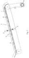
- the device for monitoring the width of the cross sealing web is connected to a conveyor 1, which continuously transports the strip-shaped packing units 6, installed (Fig. 1).
- the pack units 6 lie on angular ones Transport rails 7 and 8 forward by vertical transport fingers pushed.
- the Laser-optical sensors 2 and 3 are opposite each other with the beam direction perpendicular to the conveying direction above (sensor 2) and below (sensor 3) the Conveyor 1 arranged. They measure the distance to one of the packing units 6 and generate a voltage signal corresponding to the distance.
- each sensor is given a specified measured value of -5 V.
- Sensors 2 and 3 are read out with a clock frequency proportional to the transport speed. The clock frequency is determined by the drive shaft of the conveyor device 1 coupled clock frequency generator 4 specified.
- the measured values of sensors 2 and 3 are in accordance with the evaluation circuit in Fig. 2 processed. Both sensors are connected to a matching unit 21.
- the two analog measured values S2, S3 become the Sensors the analog differential value S2 + S3 formed and to the analog input voltage range an analog-to-digital converter 22 adapted.
- Implementation of the analog difference value S2 + S3 into a digital value 25 takes place in the analog-to-digital converter (ADU) 22 instead.
- ADU analog-to-digital converter
- 3 takes place the implementation of the analog S2 + S3 in the digital 25 difference value in ADU 22 with a clock frequency 23 instead, those coupled to the drive shaft of the conveyor 1 Clock frequency generator 4 is generated.
- the digital difference values 25 are in the Evaluation unit 24 compared with the predetermined reference value 34 (FIG. 4) and the number of difference values 25 that are below the specified reference value 34 are determined. If the number of difference values 25 determined in this way is less than one critical value, the evaluation unit 24 generates the output signal 26 which the ADU 22 and the adapter 21 controls a discharge unit 27.
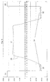
- the difference value 25 is above the clock values applied.
- the difference value lies in the area of the front sealing web 30 for approximately 60 cycles with negative values, then increases in the area of the packaged product 31 to positive values and reaches 32 in the area of the rear sealing web for about 90 Clock again difference values in the negative range.
- the difference value is at a predetermined positive value.
- FIGS. 4 and 5 the course of a measurement curve is approximately in comparison same seal bar widths and shown with different seal bar widths.
- the basic one The course of the measurement curves is that described in FIG. 3 with the areas Gap 33, front sealing bar 30, packaged product 31 and rear sealing bar 32.
- the reference value 34 is in the range of the measurement curve, which is the sealing webs 30 and 32 corresponds, drawn.
- the number of cycles for which the measurement curve is below the Reference value 34 lies, is determined and with a predetermined critical Value compared. If the number of cycles with difference values 25 is below the Reference value 34 below a specified critical value, this means that the width of the sealing web is too narrow, and as a consequence the corresponding ones are removed Packaging unit, triggered by a corresponding output signal 26, takes place.
- the number of cycles with difference values 25 is below the reference value 34 for both sealing webs with approximately 50 of approximately the same size, 5 the number of clocks with difference values 25 is below the reference value 34 in the front sealing bar 30 with about 50 significantly smaller than in the rear Siegelsteg 32 with about 90.
Landscapes
- Physics & Mathematics (AREA)
- General Physics & Mathematics (AREA)
- Containers And Plastic Fillers For Packaging (AREA)
- Package Closures (AREA)
Abstract
Description
- Fig. 1
- Vorrichtung zur Überwachung der Breite des Quersiegelsteges
- Fig. 2
- Schaltung zur Erzeugung des Ausgangssignals
- Fig. 3
- Messung der Siegelstegbreite
- Fig. 4
- Differenzwertverlauf bei annähernd gleichen Siegelstegbreiten
- Fig. 5
- Differenzwertverlauf bei ungleichen Siegelstegbreiten
Claims (11)
- Verfahren zur Überwachung der Breite des Quersiegelsteges einer in Längsrichtung taktförmig oder kontinuierlich weitertransportierten versiegelten, geschnittenen Packungseinheit (6), in der Produkte verpackt sind, dadurch gekennzeichnet dassa. von zwei laseroptischen Sensoren (2,3), die einander gegenüber oberhalb und unterhalb der geschnittenen Packungseinheiten (6) angeordnet sind, Meßwerte (S2,S3), die dem Abstand zu einer abgetasteten Oberfläche entsprechen, mit einer geschwindigkeitsproportionalen Taktfrequenz (23) erfasst werden;b. aus den beiden im selben Takt aufgenommenen Meßwerten (S2,S3) der beiden Sensoren Differenzwerte (S2+S3) gebildet werden;c. die Anzahl der aufeinanderfolgenden Differenzwerte (S2+S3), in denen ein vorgegebener Referenzwert (34) überschritten oder unterschritten wird, ermittelt wird;d. ein Ausgangssignal (26) erzeugt wird, wenn die in c. ermittelte Anzahl der Differenzwerte (S2+S3) einen vorgegebenen kritischen Wert unterschreitet.
- Verfahren nach Anspruch 1, dadurch gekennzeichnet, dass die Taktfrequenz (23) durch einen Taktfrequenzgeber (4) erzeugt wird, der an die Antriebswelle der Fördereinrichtung (1) für die Packungseinheiten (6) gekoppelt ist.
- Verfahren nach Anspruch 1 oder 2, dadurch gekennzeichnet, dass die Meßwerte (S2,S3) der laseroptischen Sensoren (2,3) bei Abtastung der Lücke zwischen zwei Packungseinheiten (6) einen vorgegebenen, konstanten Wert haben.
- Verfahren nach einem der Ansprüche 1 bis 3, dadurch gekennzeichnet, dass das Ausgangssignal (26) die Ausschleusung der entsprechenden Packungseinheit (6) auslöst.
- Vorrichtung zur Durchführung eines Verfahrens gemäß einem der Ansprüche 1 bis 4 bestehend aus zwei laseroptischen Sensoren (2,3), die einander gegenüber oberhalb und unterhalb der geschnittenen Packungseinheiten (6) angeordnet sind und deren Meßwerte (S2,S3) mit einer geschwindigkeitsproportionalen Taktfrequenz (23) erfasst werden, einem Taktfrequenzgeber (4), der die Taktfrequenz (23) zur Erfassung der Meßwerte (S2,S3) vorgibt, einer Anpassungseinheit (21), die den Differenzwert (S2+S3) aus den beiden im selben Takt gemessenen Meßwerten (S2,S3) der Sensoren (2,3) bildet und der Auswerteeinheit (24), die die Anzahl der Differenzwerte (S2+S3), die oberhalb oder unterhalb eines Referenzwertes (34) liegen, ermittelt und ein Ausgangssignal (26) erzeugt, wenn die Anzahl der Differenzwerte (S2+S3) einen vorgegebenen kritischen Wert unterschreitet.
- Vorrichtung nach Anspruch 5, dadurch gekennzeichnet, dass zwischen die Anpassungseinheit (21) und die Auswerteeinheit (24) ein Analog-Digital-Umsetzer (22) geschaltet ist, in den der Differenzwert (S2+S3) in anloger Form eingespeist wird, und der den Differenzwert (25) in digitaler Form an die Auswerteeinheit (24) weitergibt.
- Vorrichtung nach Anspruch 5 oder 6, dadurch gekennzeichnet, dass der Taktfrequenzgeber (4) so an die Antriebswelle der Fördereinrichtung (1) gekoppelt ist, dass er eine geschwindigkeitsproportionale Taktfrequenz (23) erzeugt.
- Vorrichtung nach einem der Ansprüche 5 bis 7, dadurch gekennzeichnet, dass laseroptische Sensoren (2,3), deren Meßwerte (S2,S3) farbunabhängig sind, zum Einsatz kommen.
- Vorrichtung nach einem der Ansprüche 5 bis 8, dadurch gekennzeichnet, dass im Bereich der laseroptischen Sensoren (2,3) ein Niederhalter (5) die geschnittenen Packungseinheiten (6) auf ihrer Unterlage fixiert.
- Vorrichtung nach einem der Ansprüche 5 bis 9, dadurch gekennzeichnet, dass die Signale (S2,S3) der Sensoren (2,3), die für den Bereich der Lücke zwischen zwei Packungseinheiten (6) charakteristisch sind, jeweils einen konstanten Wert haben.
- Vorrichtung nach einem der Ansprüche 5 bis 10, dadurch gekennzeichnet, dass in Förderrichtung hinter den laseroptischen Sensoren (2,3) eine Ausschleusungseinheit (27) angeordnet ist, die bei Empfang eines Ausgangssignals (26) der Auswerteeinheit (24) die entsprechende Packungseinheit (6) ausschleust.
Applications Claiming Priority (2)
| Application Number | Priority Date | Filing Date | Title |
|---|---|---|---|
| DE19931710 | 1999-07-08 | ||
| DE19931710A DE19931710C2 (de) | 1999-07-08 | 1999-07-08 | Überwachungseinrichtung für die Siegelstegbreite |
Publications (2)
| Publication Number | Publication Date |
|---|---|
| EP1070935A2 true EP1070935A2 (de) | 2001-01-24 |
| EP1070935A3 EP1070935A3 (de) | 2002-04-10 |
Family
ID=7914000
Family Applications (1)
| Application Number | Title | Priority Date | Filing Date |
|---|---|---|---|
| EP00113063A Withdrawn EP1070935A3 (de) | 1999-07-08 | 2000-06-26 | Überwachungseinrichtung für die Siegelstegbreite |
Country Status (3)
| Country | Link |
|---|---|
| US (1) | US6717087B1 (de) |
| EP (1) | EP1070935A3 (de) |
| DE (1) | DE19931710C2 (de) |
Families Citing this family (4)
| Publication number | Priority date | Publication date | Assignee | Title |
|---|---|---|---|---|
| US20070293382A1 (en) * | 2006-06-16 | 2007-12-20 | Cmd Corporation | Method and Apparatus for Making Bags |
| DE102021128978A1 (de) | 2021-11-08 | 2023-05-11 | Krones Aktiengesellschaft | Verfahren und Messanordnung zur Qualitätsprüfung von Verpackungseinheiten |
| CN114453262B (zh) * | 2021-12-20 | 2023-12-15 | 苏州镁伽科技有限公司 | 用于检测器件的方法、装置、存储介质及检测设备 |
| US11801533B1 (en) * | 2021-12-31 | 2023-10-31 | Aaron Thomas Bacon | Automated sorting of sealable bags |
Family Cites Families (20)
| Publication number | Priority date | Publication date | Assignee | Title |
|---|---|---|---|---|
| US3415369A (en) * | 1966-11-25 | 1968-12-10 | Merrell Inc Richard | Short fill detector and rejector |
| US3678176A (en) * | 1970-08-26 | 1972-07-18 | Gte Automatic Electric Lab Inc | Wire clamp terminal clip of the flanged tubular type |
| US3941485A (en) * | 1973-11-08 | 1976-03-02 | Madden Richard A | Device for continuously measuring a dimension of a workpiece by reflected light |
| US4053056A (en) * | 1976-07-19 | 1977-10-11 | Amf Incorporated | Cigarette package inspection apparatus |
| US4453083A (en) * | 1981-10-26 | 1984-06-05 | Betriebsforschungsinstitut Vdeh Institut Fur Angewandte Forschung Gmbh | Apparatus for the determination of the position of a surface |
| JPH0674968B2 (ja) * | 1988-03-15 | 1994-09-21 | 三菱電機株式会社 | 光学式測定装置 |
| JP2543620B2 (ja) * | 1990-09-13 | 1996-10-16 | シーケーディ株式会社 | 熱接着シ―ルの不良検出方法 |
| US5184190A (en) * | 1991-05-28 | 1993-02-02 | Winzen International, Inc. | Method and apparatus for detecting flaws and defects in heat seals |
| DE9116407U1 (de) * | 1991-06-07 | 1992-12-24 | Erweka GmbH, 6056 Heusenstamm | Vorrichtung zum Testen von Prüfkörpern |
| US5260766A (en) * | 1992-04-02 | 1993-11-09 | Armitage Mark H | Apparatus for detection of an imperfect seal and method therefore |
| JP2807946B2 (ja) * | 1992-07-10 | 1998-10-08 | 三共株式会社 | ガゼット包装袋口折り不良検出方法 |
| JPH0632233A (ja) | 1992-07-17 | 1994-02-08 | Nippon Cable Co Ltd | 懸垂式輸送設備の搬器の案内放送装置 |
| US5870199A (en) * | 1992-09-02 | 1999-02-09 | Betriebsforschungsinstitut Vdeh Institut Fur Angewandte Forschung Gmbh | Method and apparatus for highly accurate distance measurement with respect to surfaces |
| SE470560B (sv) * | 1993-01-11 | 1994-08-22 | Limab Laser Instrumentmek | Förfarande och anordning vid mätning av avstånd varvid ett område på ett mätföremål belyses med ljus från en laserljuskälla |
| US5861078A (en) * | 1993-08-12 | 1999-01-19 | Cmd Corporation | Method and apparatus for detecting a seal on a plastic bag |
| DE4404483A1 (de) * | 1994-02-12 | 1995-08-17 | Junghans Gmbh Geb | Verfahren zur Erkennung von Gegenständen |
| DE19505509C2 (de) * | 1995-02-10 | 2003-01-30 | Siemens Ag | Verfahren und Einrichtung zum Messen des Volumens eines bewegten Fördergutes |
| JP3511437B2 (ja) | 1996-08-07 | 2004-03-29 | 日本アビオニクス株式会社 | 自動シーリング装置におけるパッケージ認識方法 |
| DE19651954A1 (de) * | 1996-12-13 | 1998-06-18 | Bayer Bitterfeld Gmbh | Vorrichtung zum Schneiden einer Streifenverpackung |
| US6189702B1 (en) * | 1998-11-25 | 2001-02-20 | United Parcel Service Of America, Inc. | Overhead mounted sorter for conveyors |
-
1999
- 1999-07-08 DE DE19931710A patent/DE19931710C2/de not_active Expired - Fee Related
-
2000
- 2000-06-26 EP EP00113063A patent/EP1070935A3/de not_active Withdrawn
- 2000-06-28 US US09/605,190 patent/US6717087B1/en not_active Expired - Fee Related
Non-Patent Citations (1)
| Title |
|---|
| None |
Also Published As
| Publication number | Publication date |
|---|---|
| DE19931710A1 (de) | 2001-02-01 |
| EP1070935A3 (de) | 2002-04-10 |
| US6717087B1 (en) | 2004-04-06 |
| DE19931710C2 (de) | 2001-07-26 |
Similar Documents
| Publication | Publication Date | Title |
|---|---|---|
| EP0142129B1 (de) | Einrichtung zur Überwachung und Steuerung von Bahnen in Verpackungsmaschinen | |
| DE3717146C2 (de) | Austrittsvorrichtung einer Verpackungseinrichtung | |
| EP3900899B1 (de) | Vorrichtung zum aufschneiden von lebensmittelprodukten | |
| DE69020056T2 (de) | On-Line-Prägeapparat für eine Etikettiermaschine. | |
| EP1121586A1 (de) | Vorrichtung zum berührungslosen detektieren von prüfkörpern | |
| EP1882579A1 (de) | Verfahren und Vorrichtung zur Herstellung von mit einer Siegelnaht versehenen Gegenständen | |
| DE2922463A1 (de) | Verfahren und vorrichtung zum erfassen einer eigenschaft mehrerer gegenstaende | |
| EP0847926B1 (de) | Vorrichtung zum Schneiden einer Streifenverpacknung | |
| EP2228308A1 (de) | Kontrollvorrichtung für eine Produktionsmaschine | |
| EP3680604B1 (de) | Anlage und verfahren zum betreiben einer anlage zur herstellung von werkstoffplatten | |
| DE102021113754A1 (de) | Dichtheitsprüfung von Vakuumverpackungen | |
| JP2005538915A (ja) | ウェブ速度に基づく位置整合制御システム | |
| EP0401597A2 (de) | Verfahren und Vorrichtung zum Steuern eines formatlängengerechten Schneidens von Materialbahnen | |
| DE19931710C2 (de) | Überwachungseinrichtung für die Siegelstegbreite | |
| EP3143383A1 (de) | Messung der fluoreszenz eines indikators in einer gasdichten verpackung, die produkte mit limitierter lagerfähigkeit enthält | |
| EP3386691B1 (de) | Aufschneiden von lebensmittelprodukten | |
| DE2738360C3 (de) | Gerät zum Überwachen des Leerungszustandes von in einem Förderweg laufenden Umschlägen | |
| DE102012025158A1 (de) | Verfahren und Vorrichtung zur automatischen Prüfung von flächigem Folienmaterial | |
| JPH0648608A (ja) | 印刷機における印刷製品の搬送の監視法 | |
| GB1380349A (en) | Method and apparatus for inspecting dielectric articles | |
| WO2007134632A1 (de) | Verfahren zur erfassung von unregelmässigkeiten an einem messobjekt | |
| EP2141072B1 (de) | Verfahren und Vorrichtung zum Umreifen mindestens eines Stapels von Brennstoffformkörpern | |
| EP0897887B1 (de) | Verfahren und Vorrichtung zur Kontrolle der Dicke von kontinuierlich geförderten, flächigen Gegenständen | |
| DE69216222T2 (de) | Vorrichtung zur Feststellung von Fehlern bei Tragetaschen mit Handgriff | |
| DE202007000471U1 (de) | Verpackungsmaschine zur Erfassung von Unregelmäßigkeiten an einem Messobjekt |
Legal Events
| Date | Code | Title | Description |
|---|---|---|---|
| PUAI | Public reference made under article 153(3) epc to a published international application that has entered the european phase |
Free format text: ORIGINAL CODE: 0009012 |
|
| AK | Designated contracting states |
Kind code of ref document: A2 Designated state(s): AT BE CH CY DE DK ES FI FR GB GR IE IT LI LU MC NL PT SE Kind code of ref document: A2 Designated state(s): CH DE ES FR GB IT LI |
|
| AX | Request for extension of the european patent |
Free format text: AL;LT;LV;MK;RO;SI |
|
| PUAL | Search report despatched |
Free format text: ORIGINAL CODE: 0009013 |
|
| AK | Designated contracting states |
Kind code of ref document: A3 Designated state(s): AT BE CH CY DE DK ES FI FR GB GR IE IT LI LU MC NL PT SE |
|
| AX | Request for extension of the european patent |
Free format text: AL;LT;LV;MK;RO;SI |
|
| RIC1 | Information provided on ipc code assigned before grant |
Free format text: 7G 01B 11/04 A, 7G 01B 21/06 B, 7B 65B 57/10 B, 7B 07C 5/10 B, 7G 01N 21/95 B |
|
| 17P | Request for examination filed |
Effective date: 20021010 |
|
| AKX | Designation fees paid |
Free format text: CH DE ES FR GB IT LI |
|
| GRAP | Despatch of communication of intention to grant a patent |
Free format text: ORIGINAL CODE: EPIDOSNIGR1 |
|
| GRAS | Grant fee paid |
Free format text: ORIGINAL CODE: EPIDOSNIGR3 |
|
| STAA | Information on the status of an ep patent application or granted ep patent |
Free format text: STATUS: THE APPLICATION IS DEEMED TO BE WITHDRAWN |
|
| 18D | Application deemed to be withdrawn |
Effective date: 20061124 |