EP1070760A2 - High bearing pressure-resistant member and production process therefor - Google Patents
High bearing pressure-resistant member and production process therefor Download PDFInfo
- Publication number
- EP1070760A2 EP1070760A2 EP00115487A EP00115487A EP1070760A2 EP 1070760 A2 EP1070760 A2 EP 1070760A2 EP 00115487 A EP00115487 A EP 00115487A EP 00115487 A EP00115487 A EP 00115487A EP 1070760 A2 EP1070760 A2 EP 1070760A2
- Authority
- EP
- European Patent Office
- Prior art keywords
- carbide
- bearing pressure
- high bearing
- weight
- resistant member
- Prior art date
- Legal status (The legal status is an assumption and is not a legal conclusion. Google has not performed a legal analysis and makes no representation as to the accuracy of the status listed.)
- Granted
Links
Images






Classifications
-
- C—CHEMISTRY; METALLURGY
- C23—COATING METALLIC MATERIAL; COATING MATERIAL WITH METALLIC MATERIAL; CHEMICAL SURFACE TREATMENT; DIFFUSION TREATMENT OF METALLIC MATERIAL; COATING BY VACUUM EVAPORATION, BY SPUTTERING, BY ION IMPLANTATION OR BY CHEMICAL VAPOUR DEPOSITION, IN GENERAL; INHIBITING CORROSION OF METALLIC MATERIAL OR INCRUSTATION IN GENERAL
- C23C—COATING METALLIC MATERIAL; COATING MATERIAL WITH METALLIC MATERIAL; SURFACE TREATMENT OF METALLIC MATERIAL BY DIFFUSION INTO THE SURFACE, BY CHEMICAL CONVERSION OR SUBSTITUTION; COATING BY VACUUM EVAPORATION, BY SPUTTERING, BY ION IMPLANTATION OR BY CHEMICAL VAPOUR DEPOSITION, IN GENERAL
- C23C8/00—Solid state diffusion of only non-metal elements into metallic material surfaces; Chemical surface treatment of metallic material by reaction of the surface with a reactive gas, leaving reaction products of surface material in the coating, e.g. conversion coatings, passivation of metals
- C23C8/06—Solid state diffusion of only non-metal elements into metallic material surfaces; Chemical surface treatment of metallic material by reaction of the surface with a reactive gas, leaving reaction products of surface material in the coating, e.g. conversion coatings, passivation of metals using gases
- C23C8/08—Solid state diffusion of only non-metal elements into metallic material surfaces; Chemical surface treatment of metallic material by reaction of the surface with a reactive gas, leaving reaction products of surface material in the coating, e.g. conversion coatings, passivation of metals using gases only one element being applied
- C23C8/20—Carburising
- C23C8/22—Carburising of ferrous surfaces
-
- C—CHEMISTRY; METALLURGY
- C21—METALLURGY OF IRON
- C21D—MODIFYING THE PHYSICAL STRUCTURE OF FERROUS METALS; GENERAL DEVICES FOR HEAT TREATMENT OF FERROUS OR NON-FERROUS METALS OR ALLOYS; MAKING METAL MALLEABLE, e.g. BY DECARBURISATION OR TEMPERING
- C21D1/00—General methods or devices for heat treatment, e.g. annealing, hardening, quenching or tempering
- C21D1/78—Combined heat-treatments not provided for above
-
- C—CHEMISTRY; METALLURGY
- C23—COATING METALLIC MATERIAL; COATING MATERIAL WITH METALLIC MATERIAL; CHEMICAL SURFACE TREATMENT; DIFFUSION TREATMENT OF METALLIC MATERIAL; COATING BY VACUUM EVAPORATION, BY SPUTTERING, BY ION IMPLANTATION OR BY CHEMICAL VAPOUR DEPOSITION, IN GENERAL; INHIBITING CORROSION OF METALLIC MATERIAL OR INCRUSTATION IN GENERAL
- C23C—COATING METALLIC MATERIAL; COATING MATERIAL WITH METALLIC MATERIAL; SURFACE TREATMENT OF METALLIC MATERIAL BY DIFFUSION INTO THE SURFACE, BY CHEMICAL CONVERSION OR SUBSTITUTION; COATING BY VACUUM EVAPORATION, BY SPUTTERING, BY ION IMPLANTATION OR BY CHEMICAL VAPOUR DEPOSITION, IN GENERAL
- C23C8/00—Solid state diffusion of only non-metal elements into metallic material surfaces; Chemical surface treatment of metallic material by reaction of the surface with a reactive gas, leaving reaction products of surface material in the coating, e.g. conversion coatings, passivation of metals
- C23C8/80—After-treatment
-
- F—MECHANICAL ENGINEERING; LIGHTING; HEATING; WEAPONS; BLASTING
- F16—ENGINEERING ELEMENTS AND UNITS; GENERAL MEASURES FOR PRODUCING AND MAINTAINING EFFECTIVE FUNCTIONING OF MACHINES OR INSTALLATIONS; THERMAL INSULATION IN GENERAL
- F16C—SHAFTS; FLEXIBLE SHAFTS; ELEMENTS OR CRANKSHAFT MECHANISMS; ROTARY BODIES OTHER THAN GEARING ELEMENTS; BEARINGS
- F16C19/00—Bearings with rolling contact, for exclusively rotary movement
- F16C19/02—Bearings with rolling contact, for exclusively rotary movement with bearing balls essentially of the same size in one or more circular rows
- F16C19/10—Bearings with rolling contact, for exclusively rotary movement with bearing balls essentially of the same size in one or more circular rows for axial load mainly
-
- F—MECHANICAL ENGINEERING; LIGHTING; HEATING; WEAPONS; BLASTING
- F16—ENGINEERING ELEMENTS AND UNITS; GENERAL MEASURES FOR PRODUCING AND MAINTAINING EFFECTIVE FUNCTIONING OF MACHINES OR INSTALLATIONS; THERMAL INSULATION IN GENERAL
- F16C—SHAFTS; FLEXIBLE SHAFTS; ELEMENTS OR CRANKSHAFT MECHANISMS; ROTARY BODIES OTHER THAN GEARING ELEMENTS; BEARINGS
- F16C33/00—Parts of bearings; Special methods for making bearings or parts thereof
- F16C33/30—Parts of ball or roller bearings
-
- C—CHEMISTRY; METALLURGY
- C21—METALLURGY OF IRON
- C21D—MODIFYING THE PHYSICAL STRUCTURE OF FERROUS METALS; GENERAL DEVICES FOR HEAT TREATMENT OF FERROUS OR NON-FERROUS METALS OR ALLOYS; MAKING METAL MALLEABLE, e.g. BY DECARBURISATION OR TEMPERING
- C21D2211/00—Microstructure comprising significant phases
- C21D2211/002—Bainite
-
- C—CHEMISTRY; METALLURGY
- C21—METALLURGY OF IRON
- C21D—MODIFYING THE PHYSICAL STRUCTURE OF FERROUS METALS; GENERAL DEVICES FOR HEAT TREATMENT OF FERROUS OR NON-FERROUS METALS OR ALLOYS; MAKING METAL MALLEABLE, e.g. BY DECARBURISATION OR TEMPERING
- C21D2211/00—Microstructure comprising significant phases
- C21D2211/003—Cementite
-
- C—CHEMISTRY; METALLURGY
- C21—METALLURGY OF IRON
- C21D—MODIFYING THE PHYSICAL STRUCTURE OF FERROUS METALS; GENERAL DEVICES FOR HEAT TREATMENT OF FERROUS OR NON-FERROUS METALS OR ALLOYS; MAKING METAL MALLEABLE, e.g. BY DECARBURISATION OR TEMPERING
- C21D2211/00—Microstructure comprising significant phases
- C21D2211/008—Martensite
-
- C—CHEMISTRY; METALLURGY
- C21—METALLURGY OF IRON
- C21D—MODIFYING THE PHYSICAL STRUCTURE OF FERROUS METALS; GENERAL DEVICES FOR HEAT TREATMENT OF FERROUS OR NON-FERROUS METALS OR ALLOYS; MAKING METAL MALLEABLE, e.g. BY DECARBURISATION OR TEMPERING
- C21D6/00—Heat treatment of ferrous alloys
- C21D6/002—Heat treatment of ferrous alloys containing Cr
-
- C—CHEMISTRY; METALLURGY
- C21—METALLURGY OF IRON
- C21D—MODIFYING THE PHYSICAL STRUCTURE OF FERROUS METALS; GENERAL DEVICES FOR HEAT TREATMENT OF FERROUS OR NON-FERROUS METALS OR ALLOYS; MAKING METAL MALLEABLE, e.g. BY DECARBURISATION OR TEMPERING
- C21D9/00—Heat treatment, e.g. annealing, hardening, quenching or tempering, adapted for particular articles; Furnaces therefor
- C21D9/36—Heat treatment, e.g. annealing, hardening, quenching or tempering, adapted for particular articles; Furnaces therefor for balls; for rollers
Definitions
- This invention relates to a member applied as a motive power transmission part requiring a high degree of surface fatigue strength in the manner of gears and bearing rolling elements, and more particularly, to a high bearing pressure-resistant member and a production process of such a high bearing pressure-resistant member that is suitable for use under high bearing pressure in semi-high-temperature to high-temperature environments (of roughly within a range of from 100 to 300°C).
- a motive power transmission part of the prior art like that described above is used after subjecting to surface hardening treatment such as carburization and carbonitriding having for its base material (matrix) mechanical structure steel represented by SCr420H steel (chromium steel) and SCM420H steel (chromium-molybdenum steel) defined in JIS G 4052 (structural steel materials having guaranteed quenching).
- matrix mechanical structure steel represented by SCr420H steel (chromium steel) and SCM420H steel (chromium-molybdenum steel) defined in JIS G 4052 (structural steel materials having guaranteed quenching).
- cementite is susceptible to precipitation in the form of a coarse reticular form along the grain boundary during carburization, and the coarse carbide (cementite) precipitated in reticular form near the grain boundary results in quench cracking that not only lowers tenacity, but also decreases rolling fatigue strength.
- Another object of the present invention is to provide an improved high bearing pressure-resistant member and a process of producing the same member, which high bearing pressure-resistant member has excellent surface fatigue strength such as pitting strength and rolling fatigue strength even under semi-high to high temperatures and high bearing pressure such that local bearing pressure exceeds 3 GPa, while also inhibiting increases in base material cost and decreases in cutting ease caused by the addition of large amounts of alloy elements in comparison with AISI M50 of the prior art, and not requiring complex heat treatment.
- An aspect of the present invention resides in a high bearing pressure-resistant member which is formed of a mechanical structural steel containing Cr.
- the mechanical structural steel includes a matrix having at least one of martensite structure and bainite structure.
- the matrix contains carbide having a mean particle size of 3 ⁇ m or less, dispersed and precipitated in form of at least one of generally spheres and pseudo-spheres.
- a further aspect of the present invention resides in a process of producing a high bearing pressure-resistant member.
- a high bearing pressure-resistant member is formed of a mechanical structural steel containing Cr.
- the mechanical structural steel includes a matrix having at least one of martensite structure and bainite structure.
- the matrix contains carbide having a mean particle size of 3 ⁇ m or less, dispersed and precipitated in form of at least one of generally spheres and pseudo-spheres.
- the carbide includes M 23 C 6 -type carbide where M is a metal element.
- the form of spheres means generally spherical shapes, and the form of pseudo-spheres means deformed spherical shapes.
- the high bearing pressure-resistant member can secure a high degree of hardness even at semi-high to high temperatures (generally 100 to 300 °C) and has excellent surface fatigue strength even under high bearing pressure such as local bearing pressure exceeds 3 GPa.
- the Cr is an alloy component that is required as an element that forms the carbide, and particular M 23 C 6 -type carbide, it is only required to be added at 1-4%, and does not cause an increase in the cost of the base material (matrix) or a decrease in cutting ease.
- examples of steels containing Cr that can be used include, according to JIS, chromium steel (SCr series) defined in G 4104, chromium-molybdenum steel (SCM series) defined in G 4105, and nickel-chromium-molybdenum steel (SNCM series) defined in G 4103.
- examples of steels according to ASTM include A387Gr11, Gr21 and Gr22 steels. Such steels serve as raw material (or material member) for the high bearing pressure-resistant member according to the present invention.
- the high bearing pressure-resistant member is formed by dispersing and precipitating microcarbides having a mean particle size of 3 ⁇ m or less in the form of spheres or pseudo-spheres in a base (matrix) of martensite or bainite mechanical structural steel containing 1.2-3.2% Cr and 0.25-2.0% Mo, and therefore has excellent surface fatigue strength even under the semi-high to high temperatures.
- the Cr in the present invention is an alloy component that is required as an element that forms the carbide, and particular M 23 C 6 -type carbide, it is only required to be added within the above range, and does not cause an increase in the cost of the base material (matrix) or a decrease in cutting ease.
- % used in this specification is “% by weight” except for that of area ratio (rate). If the amount of this Cr is less than 1.2%, the amount of carbide precipitated decreases thereby preventing the expected rolling fatigue service life from being obtained. On the other hand, if the amount of this Cr exceeds 3.2%, there is the risk of a decrease in cutting ease. In addition, addition of Mo simultaneous to addition of Cr results in stable precipitation of M 23 C 6 -type carbide. If the amount of Mo is less than 0.25%, the effect of stabilizing precipitation cannot be expected. If the amount of Mo exceeds 2% however, cutting ease decreases.
- the high bearing pressure-resistant member of the present invention since its S content is 0.01% or less, although MnS-based inclusions are reduced and machinability decreases, a stable long service life is obtained. If the amount of S exceeds 0.01%, while MnS-based inclusions facilitate cutting, the probability of the occurrence of internal origin separation starting at MnS-based inclusions under rolling contact increases, making it difficult to obtain a stable service life.
- the amount of nitrogen solid solution at least at the location from the surface to the surface formed after grinding is within a range of from 0.01 to 0.5%, and solid solutions of nitrogen have the effect of spreading Acm lines into high carbon regions, the precipitation of reticular carbide is prevented by adding at 0.01% or more.
- the amount of nitrogen solid solution exceeds 0.5%, the amount of nitrogen solid solution in the matrix increases and tends to decrease the amount of precipitation of M 23 C 6 -type carbide.
- the high bearing pressure-resistant member of the present invention contains M 23 C 6 -type carbide as the carbide, this carbide is dispersed extremely finely in martensite or bainite structures, is resistant to sources of stress concentration, is not softened even under the semi-high to high temperatures, and maintains a high degree of hardness.
- carbide at a surface area ratio (rate)ranging from 0.3 to 30% is dispersed and precipitated at a location at least from the surface susceptible to the occurrence of internal separation to the depth of occurrence of maximum shearing stress caused by rolling contact, it has excellent surface fatigue strength such as pitting strength and rolling fatigue strength. Furthermore, when the precipitated surface area of carbide at this time does not reach 0.3%, there is no improvement in cold hardness or temper hardness and adequate pitting strength and rolling fatigue strength are unable to be obtained. When the precipitated surface area of carbide exceeds 30%, in addition to tenacity decreasing, there is a shortage of alloy elements in the matrix due to alloy elements going into solid solution in the carbide, resulting in the tendency to locally form a soft layer.
- the high bearing pressure-resistant member of the present invention demonstrates its characteristics particularly by being applied to motive force transmission parts requiring surface fatigue strength under high bearing pressure, and rolling elements for toroidal continuously variable transmissions requiring rolling fatigue strength under high bearing pressure, and contributes to reduced size and improved longevity of the apparatus in which it is applied.
- the following production process of a high bearing pressure-resistant member of the present invention is suitable for the production of the above high bearing pressure-resistant member.
- this production process inhibits the precipitation of coarse, reticular M 3 C-type carbide in the surface portion that includes the location of maximum shearing stress depth caused by rolling contact, allows the precipitation of fine M 23 C 6 -type carbide that is stable even at semi-high to high temperatures, and allows the matrix after quenching to have a martensite or bainite structure.
- a high bearing pressure-resistant member is obtained that secures high hardness even at the semi-high to high temperatures, and has excellent surface fatigue strength such as pitting strength and rolling fatigue strength even under high bearing pressure such that local bearing pressure exceeds 3 GPa.
- the surface carbon density of the carburized layer is less than 0.6%, it is not possible to secure hardness. Conversely, in the case the surface carbon density exceeds 1.5%, there is increased susceptibility to precipitation of M 3 C-type carbide, and there is reticular growth at a mean particle size that exceeds 3 ⁇ m thereby making this undesirable. Furthermore, there are no particular restrictions on the method of carburization treatment, and although methods such as solid carburization, liquid carburization or gas carburization can be used, it is preferable to employ vacuum carburization or plasma carburization if possible.
- the Cr in the raw material steel in the present invention is an essential alloy component that forms carbide, and particularly M 23 C 6 -type carbide, its amount added is preferably about 1 to 4% from the viewpoint of ensuring its action while avoiding increases in cost and decreased cutting ease.
- the above equation T that is used to calculate the upper limit value of the holding temperature for precipitating carbide was determined as a result of numerous experiments, and by holding the member after carburization treatment equal to or below temperature T (°C) calculated according to its alloy components, M 23 C 6 -type carbide is precipitated. Since the mean particle size of M 23 C 6 -type carbide is extremely minute at 1 ⁇ m or less, it is unlikely to be a source of stress concentration. Since it is also dispersed and precipitated within crystal grains of martensite or bainite, it is resistant to softening at the semi-high and high temperatures, thereby ensuring high hardness.
- the production process consisting mainly of a carburization step, carbide precipitation step and quenching step, wherein carburization treatment is performed on a member comprising mechanical structural steel containing 1.2 to 3.2% of Cr and 0.25 2.0% of Mo, carburization treatment is performed such that the surface carbon density is within a range of from 0.6 to 1.5% and the carbon density at the depth location of occurrence of the maximum shearing stress caused by rolling contact is within the range of 0.5% or more, carbide is precipitated while holding the carburized member at a temperature having for its upper limit temperature T (°C) as calculated from the above equation, and quenching is performed after holding at the austenite region temperature.
- T upper limit temperature
- the precipitation of coarse, reticular M 3 C-type carbide at the surface layer portion that includes the depth location of maximum shearing stress caused by rolling contact is inhibited, microscopic M 23 C 6 -type carbide that is stable even at semi-high and high temperatures is precipitated, and the matrix after quenching becomes a martensite or bainite structure, thereby allowing the obtaining of a high bearing pressure-resistant member that secures high hardness even at the semi-high to high temperatures, and has excellent surface fatigue strength such as pitting strength and rolling fatigue strength even under high bearing pressure such that local bearing pressure exceeds 3 GPa.
- the carbide surface area ratio (rate) at this depth location (or surface area ratio of the precipitated carbide at the location of a depth of 0.1 mm, as discussed after) is unable to reach 0.3%, thereby failing to improve cold hardness or temper hardness and preventing the obtaining of adequate pitting strength and rolling fatigue strength.
- the carburization treatment method there are no particular restrictions on the carburization treatment method and although methods such as solid carburization, liquid carburization or gas carburization can be used, it is preferable to employ vacuum carburization or plasma carburization if possible.
- the Cr in the raw material steel in the present invention is an essential alloy component that forms carbide, and particularly M 23 C 6 -type carbide, as is previously mentioned, its amount added is preferably about 1.2-3.2% from the viewpoint of ensuring its action while avoiding increases in cost and decreased cutting ease.
- Mo is added since addition simultaneous to Cr allows stable precipitation of M 23 C 6 -type carbide, if the amount of Mo added is less than 0.25%, stable precipitation of M 23 C 6 -type carbide cannot be expected, and if the amount added exceeds 2%, cutting ease tends to decrease.
- the higher the temperature of diffusion the larger the diffusion coefficient of carbon inside, and although this facilitates the disappearance of reticular carbide, if the ratio of Td/Tc exceeds 1.25, since there is melting of the steel surface, it is preferable that the upper limit of this ratio be 1.25.
- the cooling rate at this time be 10°C/minute or more.
- Preferable methods for achieving a cooling rate of 10°C/minute or more include gas cooling to the carbide precipitation temperature in a carburization diffusion chamber, transferring to a cooling chamber outside the carburization diffusion chamber and lowering to the carbide precipitation temperature, and temporarily quenching after carburization diffusion followed by heating to the carbide precipitation temperature.
- a high bearing pressure-resistant member of the present invention consisting of precipitating carbide while holding a member composed of mechanical structural steel containing Cr and 0.6-1.5% carbon at a temperature having for its upper limit temperature T (°C) calculated from the above equation, followed by performing quenching after holding at the austenite region temperature.
- a high bearing pressure-resistant member of the present invention consisting of precipitating carbide by holding a member composed of mechanical structural steel containing 1.2 to 3.2% of Cr, 0.25 to 2.0% of Mo and 0.6 to 1.5% of C at a temperature having for its upper limit temperature T (°C) calculated from the above equation and quenching by cooling rapidly after holding at the austenite region temperature.
- a carburization step is similarly not required, precipitation of coarse, reticular M 3 C-type carbide at the surface layer portion that contains the depth location of maximum shearing stress caused by rolling contact is similarly inhibited, microscopic M 23 C 6 -type carbide that is stable even at the semi-high to high temperatures (300°C or less) is precipitated and the matrix becomes a martensite or bainite structure, thereby allowing the obtaining of a high bearing pressure-resistant member that secures high hardness and has excellent surface fatigue strength such as pitting strength and rolling fatigue strength even under high bearing pressure such that local bearing pressure exceeds 3 GPa.
- Plasma carburization was used for the carburization method at this time.
- Type of Steel Chemical Composition (wt%) T C Si Mn S Ni Cr Mo V O A 0.20 1.00 0.30 0.005 2.0 1.50 1.50 0.19 Max. 12 ppm 1032.5 B 0.24 1.01 0.35 0.004 1.9 1.95 0.95 0.20 Max. 12 ppm 927.65 C 0.20 1.05 0.32 0.003 2.0 2.55 0.78 0.21 Max. 12 ppm 907.2 D 0.18 1.03 0.39 0.003 2.1 2.10 0.70 0.00 Max. 12 ppm 955.4 E 0.20 1.00 0.35 0.005 2.2 2.00 0.29 0.18 Max. 12 ppm 785.95 F 0.19 1.02 0.40 0.004 1.1 2.00 0.69 0.19 Max.
- a) Roller pitting tester was produced by Komatsu Engineering Corp.
- "SUJ2" was high carbon chromium bearing steel according to JIS G 4805.
- Slip ratio was a difference (%) of a rotational speed of the roller test piece 1 to that of the disk-shaped partner material 2.
- disk-shaped test piece 3 and three spheres 5 as partner materials were combined in lubricating oil 4 using a thrust-type rolling fatigue tester as shown in Fig. 2, and thrust test life (L50) of disk-shaped test piece 3 was determined as follows: Five rolling fatigue tests were repeated to obtain test result of number (times) of turning of three spheres 5 along the periphery of disk-shaped test piece 3 at a time when separation or peeling occurred under the conditions shown in Table 3. Then five test results were plotted on a Wiebull probability paper, thereby determining the damage probability 50% life (L50) which was the life (the above turning number)until the separation or peeling occurred. Tester Thrust-type rolling fatigue tester Bearing pressure 5.23 GPa Max.
- Thrust-type rolling fatigue tester was produced by Japan Tobacco Inc.
- the cross-section of the thrust-type test piece obtained in the above manner was corroded with an alcohol solution containing 3% nitric acid, and after taking microphtographs at 10,000 magnifications of first cross-section of the test piece extending from the uppermost surface to a depth of 0.1 mm and of second cross-section (of the test piece) perpendicular to the first (vertical) cross-section by using a scanning electron microscope.
- the microphotograph of the microstructure of invention example 1 is shown in Fig. 11.
- the microphotograph of Fig. 11 was subjected to image processing thereby providing an image shown in Fig. 12.
- the second cross-section was located at a depth of 0.1 mm of the test piece.
- mean particle size of the precipitated carbide at the first cross-section and surface area ratio (rate) of the precipitated carbide at the second cross-section were measured using an image analyzer.
- test piece was subjected to tempering treatment for 3 hours at 300°C followed by measurement of hardness for the purpose of evaluating temper softening resistance.
- microscopic M 23 C 6 -type carbide having a mean particle size of 0.3 ⁇ m or less was precipitated at a surface area ratio of about several percent to 30%, thereby resulting in a member having improved cold hardness and excellent hardness after tempering treatment for 3 hours at 300°C (temper softness resistance), which was confirmed to drastically improve pitting life and rolling fatigue life.
- invention example 13 in which carbide precipitation treatment for 30 minutes at 750°C, which correspond to a higher temperature and shorter duration than invention example 10, was performed on steel having a base metal (matrix) C content of 0.8%, followed by precipitation of carbide to the equilibrium state (maximum) and similarly quenching and tempering, since the base metal (matrix) C content is lower than invention example 10, the surface area ratio of M 23 C 6 -type carbide resulting in decreases in cold hardness and temper hardness.
- the structure contained precipitates of microscopic M 23 C 6 -type carbide, the life was longer than that of the comparative examples.
- invention example 15 after performing carbide precipitation treatment for 5 hours at 650°C on steel having a base metal (matrix) C content of 1.0% and precipitating carbide to an equilibrium state (maximum) in the same manner as invention example 10 followed by heating for 8 seconds at a constant output of 200 kW and constant frequency of 10 kHz using a high-frequency heater, the structure was quenched in oil at 60°C. As a result, a structure similar to invention example 10 was obtained and was demonstrated to have long life. Furthermore, since heating and holding times are shortened considerably when high-frequency quenching is applied, heat treatment cost can be further reduced in comparison with invention example 10 in which carburization treatment is not performed.
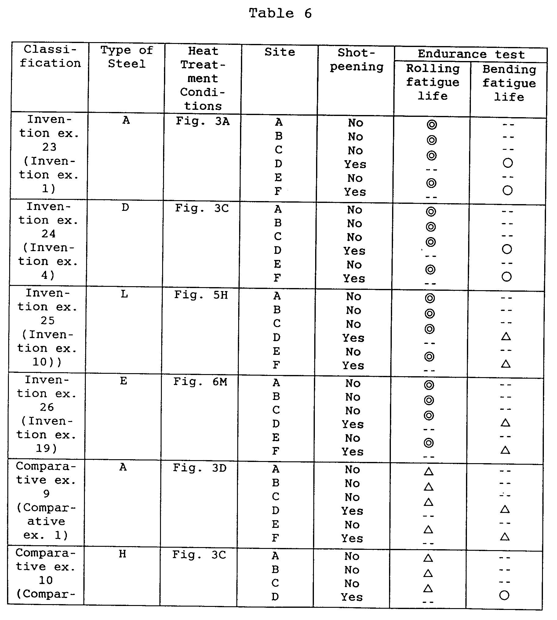
- the rolling elements according to invention examples 23, 24, 25 and 26 (these respectively coincide with the combinations of steel types and heat treatment conditions of invention examples 1, 4, 10 and 19 in Embodiment 1) had a structure in which M 23 C 6 -type carbide was precipitated. Consequently, since the temper hardness at the rolling contact surface is high, there is resistance to plastic deformation even at high contact bearing pressures. In addition, since there is high temper hardness even at the location of the depth of maximum shearing stress, there is little susceptibility to the occurrence of structural changes caused by rolling fatigue, thereby resulting in long life.
- An anti-pitting test was then performed using a power circulating type of gear pitting tester based on the conditions of a Hertz bearing pressure at the gear pitting point of 2.0 GPa, test gear rotating speed of 1000 rpm, automatic transmission fluid (ATF) for the oil type and an oil temperature of 120°C. Pitting life was evaluated in terms of the total number of rotations until the surface area of separation caused by pitting that occurred on the tooth surfaces of the test gear reached a surface area equivalent to 3% of the effective meshing surface area of the entire gear.
- ATF automatic transmission fluid
- a high bearing pressure-resistant member such as a toroidal continuously variable transmission in the form of disk and power roller makes rolling contact under a harsh environment of high speed and high temperature while being subjected to a heavy load.
- This environment is becoming increasing harsh accompanying reduced size and higher capacities of transmissions and power transfer units using such high bearing pressure members.
- the rolling portions of these members (for example, the traction surfaces and bearing grooves in the case of discs and power rollers) are required to be resistant to the internal origin separation caused by rolling fatigue as well as high rolling fatigue strength.
- the base material (matrix) takes on a martensite or bainite structure and there is hardly any carbide present.
- the base material (matrix) of the high bearing pressure-resistant member includes a martensite and/or bainite structure and contains microscopic carbide having a mean particle size of 3 ⁇ m or less is dispersed and precipitated in the form of spheres or pseudo-spheres in this base material, room temperature hardness of the high bearing pressure-resistant member increases, reductions in hardness under high temperatures of the same are inhibited and internal origin rolling fatigue life of the same is improved.
- the high bearing pressure-resistant member includes a biphasic structure provided with a first phase composed of martensite and/or bainite that is substantially free of carbide, and a second phase in which microscopic carbide is dispersed and precipitated in the form of spheres or pseudo-spheres in the manner described above in the base material (matrix) having a martensite and/or bainite structure.
- the high bearing pressure-resistant member has both higher rolling fatigue strength and bending fatigue strength than a case where carbide are uniformly precipitated throughout the entire region.
- the mean particle size of the carbide in the second phase region exceeds 3 ⁇ m or the carbide is precipitated in reticular form instead of in the form of spheres or pseudo-spheres, although room temperature hardness and high-temperature softening resistance are improved, the action of improving rolling fatigue life decreases because the precipitated carbide acts as a source of stress concentration resulting in increased susceptibility of the formation of crack starting points and propagation routes.
- M 23 C 6 -type carbide containing Cr is more preferable than M 3 C-type carbide for use as the carbide at this time since it tends to be stable even during rolling fatigue at high temperatures, inhibit decreases in hardness, and improve rolling fatigue life by delaying changes in the internal structure.
- the surface area ratio of the above carbide in the second phase region be within the range of 0.3-30% relative to the total area of the first and second phase region. Namely, in the case the surface area ratio of carbide in the second phase region is less than 0.3%, inhibition of high-temperature softening and the action of delaying structural changes are inadequately obtained. Conversely, in the case the surface area ratio exceeds 30%, decreases in alloy elements and carbon density in the base material (matrix) are made and therefore invite decreased hardness of the base material, thereby tending to prevent adequate improvement of rolling fatigue life.
- the S content be 0.01% or less. If this is done, although MnS-based inclusions are reduced and machinability decreases, a stable, long service life is obtained. If the amount of S exceeds 0.01%, although MnS-based inclusions facilitate cutting, the probability of the occurrence of internal origin separation starting at MnS-based inclusions under rolling contact increases, making it difficult to obtain a stable service life.
- the amount of nitrogen solid solution in its surface is within a range of from 0.01 to 0.5%, and solid solutions of nitrogen have the effect of spreading Acm lines into high carbon regions, the precipitation of reticular carbide is prevented by adding at 0.01% or more.
- the amount of nitrogen solid solution exceeds 0.5%, the amount of nitrogen solid solution in the matrix increases and tends to decrease the amount of precipitation of M 23 C 6 -type carbide.
- the surface carbon density at the site subjected to rolling fatigue caused by rolling contact is within a range of from 0.6 to 1.5%, a high degree of strength is maintained and fatigue strength is improved.
- the carbon density at this time is less than 0.6%, since the carbide surface area ratio in the second phase cannot be secured, hardness can no longer be maintained.
- the surface carbon density exceeds 1.5%, there is greater susceptibility to precipitation of M 3 C-type carbide, and this tends to grow in reticular form at a mean particle size in excess of 3 ⁇ m.
- the high bearing pressure-resistant member of the present invention is suitably applied in the rolling elements of a toroidal continuously variable transmission, namely the discs or power rollers of a toroidal continuously variable transmission, and contributes to reduced size, increased capacity and extension of service life of the toroidal continuously variable transmission.
- both rolling fatigue strength and bending fatigue strength is preferable to be realized in the discs and power rollers of toroidal continuously variable transmissions. Moreover, those demand characteristics are not necessarily uniform, and each differ depending on the site of each rolling element. This will be discussed in detail with reference to Figs. 7, 8A and 8B.
- the surface area ratio of the second phase in which carbide is finely dispersed and precipitated be 3% or more, and more preferably 50% or more at least in the surface portion at that site down to the depth of occurrence of maximum shearing stress.
- the carbon density be 0.5% or more at the above-mentioned site since this results in adequate pitting strength and rolling fatigue strength. Furthermore, in the case the carbon density is less than 0.5%, it is not possible to secure the carbide surface area ratio at the location of the depth of occurrence of maximum shearing stress caused by rolling contact, and this tends to make it difficult to improve cold hardness and temper hardness.
- the surface area ratio of the second phase in which carbide is finely dispersed and precipitated be 3-100% on the uppermost surface, and more preferably within the range of from 50 to 80%.
- the first phase which has lower hardness and a large amount of residual austenite than the second phase, alleviates stress concentration of indentations on the uppermost surface and improves resistance to the intrusion of foreign matter.
- the surface area ratio of the above second phase be 90% or less, and more preferably 30% or less at the uppermost surface, and that shot-peening be performed.
- the surface area ratio of the second phase at this time exceeds 90%, in addition to it being easier for the carbide dispersed in the second phase to act as the starting point or propagation route for cracks, the machining-induced transformation of the first phase becomes inadequate, and there is increased susceptibility to the formation of microscopic cracks during shot-peening, which tends to decrease the amount of improvement in bending fatigue strength.
- the biphasic structure including the first phase having a martensite and/or bainite structure that is substantially free of precipitation of carbide, and the second phase, in which carbide is finely dispersed and precipitated in the base material (matrix) having a martensite and/or bainite structure, is obtained by precipitating carbide by holding at a prescribed temperature for a prescribed period of time either after performing carburization treatment on mechanical structural steel containing carbide forming elements such as Cr and Mo, or without performing carburization treatment by using mechanical structural steel containing a prescribed amount of Cr, and then quenching by heating and holding at the austenite region temperature and finally performing tempering treatment.
- the surface area ratio of the second phase can be controlled by adjusting the surface carbon density by carburization treatment, adjusting the holding temperature and holding time in the carbide precipitation step, and adjusting the holding temperature and holding time at the austenite region temperature.
- the surface area of the second phase becomes larger, as the surface carbon density by carburization treatment becomes higher, as the holding temperature of the carbide precipitation step becomes higher, as the longer the holding time becomes higher, or as the holding temperature in the austenite region prior to quenching becomes lower.
- the following production process of the high bearing pressure-resistant member is suitable for the production of the high bearing pressure-resistant member of the present invention.
- this production process for the high bearing pressure-resistant member inhibits the precipitation of coarse, reticular M 3 C-type carbide in the surface portion that includes the location of maximum shearing stress depth caused by rolling contact, allows the obtaining of a first phase in which carbide is substantially not precipitated, and a second phase in which fine M 23 C 6 -type carbide that is stable even at the semi-high to high temperatures is precipitated and the matrix after quenching has a martensite and/or bainite structure.
- the high bearing pressure-resistant member is obtained that secures high hardness even at the semi-high to high temperatures, and has excellent surface fatigue strength such as pitting strength and rolling fatigue strength even under high bearing pressure such that local bearing pressure exceeds 3 GPa.
- the surface carbon density of the carburized layer is less than 0.6%, it is not possible to secure hardness. Conversely, in the case the surface carbon density exceeds 1.5%, there is increased susceptibility to precipitation of M 3 C-type carbide, and there is reticular growth at a mean particle size that exceeds 3 ⁇ m thereby making this undesirable. Furthermore, there are no particular restrictions on the method of carburization treatment, and although methods such as solid carburization, liquid carburization or gas carburization can be used, it is preferable to employ vacuum carburization or plasma carburization if possible.
- the Cr in the raw material steel (or the material member) in the present invention is an essential alloy component that forms carbide, and particularly M 23 C 6 -type carbide, its amount added is preferably about 1 to 4% from the viewpoint of ensuring its effect while avoiding increases in cost and decreased cutting ease.
- the above equation T that is used to calculate the upper limit value of the holding temperature for precipitating carbide was determined as a result of numerous experiments, and by holding the (material) member after carburization treatment to temperature Tp (°C) equal to or below temperature T (°C) calculated according to the alloy components of the member, M 23 C 6 -type carbide is precipitated. Since the mean particle size of M 23 C 6 -type carbide is extremely minute at 1 ⁇ m or less, it is unlikely to be a source of stress concentration. Since it is also dispersed and precipitated within crystal grains of martensite and/or bainite, it is resistant to softening at semi-high and high temperatures, thereby ensuring high hardness.
- the time of carbide precipitation treatment namely the holding time at temperature Tp (°C), shorter than time t as calculated according to equation t corresponding to the above-mentioned precipitation temperature Tp (°C)
- precipitation is discontinued prior to reaching equilibrium.
- the lower limit temperature of carbide precipitation treatment be 550°C or higher from the viewpoint of productivity.
- the upper limit t of holding time during carbide precipitation treatment is calculated according to the above second calculation equation, such that, for example, t is approximately 58 hours when holding temperature T is 600°C, t is approximately 3.85 hours when T is 650°C, t is approximately 0.34 hours (approximately 20 minutes) when T is 700°C, and t is approximately 0.037 hours (approximately 2.5 minutes) when T is 750°C.
- the production process of the high bearing pressure-resistant member of the present invention is also suitable for production of the above high bearing pressure-resistant member of the present invention, consisting mainly of a carburization step, carbide precipitation step and quenching step, wherein carburization treatment is performed on a member comprising mechanical structural steel containing 1.2 to 3.2% of Cr and 0.25 to 2.0% of Mo, carburization treatment is performed such that the surface carbon density is within a range of from 0.6 to 1.5% and the carbon density at the depth location of occurrence of the maximum shearing stress caused by rolling contact is within the range of 0.5% or more, carbide is precipitated while holding the carburized member at a precipitation temperature Tp (°C) having for its upper limit temperature T (°C) as calculated from the above first equation for an amount of time that is shorter than time t (hr.) calculated from the above second equation, and quenching is performed after holding at the austenite region temperature, a similar biphasic structure results that is composed of a first phase and second phase, and a
- the surface carbon density of the carburized layer is less than 0.6%
- hardness can similarly not be secured, and conversely if the surface carbon density exceeds 1.5%, there is increased susceptibility to precipitation of M 3 C-type carbide that grows in a reticular form having a mean particle size in excess of 3 ⁇ m, thereby making this undesirable.
- the carbon density at the depth location of maximum shearing stress caused by rolling contact is less than 0.5%
- the carbide surface area ratio at this depth location is unable to reach 0.3%, thereby failing to improve cold hardness or temper hardness and preventing the obtaining of adequate pitting strength and rolling fatigue strength.
- the Cr in the raw material steel in the present invention is an essential alloy component that forms carbide, and particularly M 23 C 6 -type carbide, as is previously mentioned, its amount added is preferably about 1.2 to 3.2% from the viewpoint of ensuring its action while avoiding increases in cost and decreased cutting ease.
- Mo is added since addition simultaneous to Cr allows stable precipitation of M 23 C 6 -type carbide, if the amount of Mo added is less than 0.25%, stable precipitation of M 23 C 6 -type carbide cannot be expected, and if the amount added exceeds 2%, cutting ease tends to decrease.
- the cooling rate at this time be 10°C/minute or more.
- Preferable methods for achieving a cooling rate of 10°C/minute or more include gas cooling to the intermediate holding temperature in a carburization diffusion chamber, transferring to a cooling chamber outside the carburization diffusion chamber and lowering to the intermediate holding temperature, and temporarily quenching after carburization diffusion followed by heating to the intermediate holding temperature.
- nitriding is performed either simultaneous to carburization (carburization nitriding) or following completion of carburization, and therefore precipitation of reticular carbide is prevented by nitrogen in solid solution.
- the production process of the high bearing pressure-resistant member of the present invention preferably includes precipitating carbide while holding a member (material member) composed of mechanical structural steel containing Cr and 0.6 1.5% of carbon at a precipitation temperature Tp (°C) having for its upper limit temperature T (°C) calculated from the above first equation for an amount of time shorter than time t (hr.) calculated according to the above second equation, followed by performing quenching after holding at the austenite region temperature.
- the production process of the high bearing pressure-resistant member of the present invention preferably includes precipitating carbide by holding a member composed of mechanical structural steel containing 1.2 to 3.2% of Cr, 0.25 to 2.0% of Mo and 0.6 to 1.5% of C at a precipitation temperature Tp (°C) having for its upper limit temperature T (°C) calculated from the above first equation for an amount of time shorter than time t (hr.) calculated according to the above second equation, and quenching by cooling rapidly after holding at the austenite region temperature.
- a carburization step is similarly not required, and precipitation of coarse, reticular M 3 C-type carbide at the surface layer portion that contains the depth location of maximum shearing stress caused by rolling contact is similarly inhibited.
- a biphasic structure consisting of a first phase that does not contain carbide and a second phase in which microscopic carbide is precipitated in a matrix consisting of martensite and/or bainite. Consequently, a high bearing pressure-resistant member can be inexpensively obtained that secures high hardness and has excellent surface fatigue strength such as pitting strength and rolling fatigue strength even under high bearing pressure.
- the nitriding treatment at this time may be performed before or after the carbide precipitation step.
- this step can be simplified in the case the austenite region temperature coincides with the carbide precipitation temperature, thereby enabling cost to be reduced.
- Plasma carburization was used for the carburization method at this time.
- Type of Steel Chemical Composition (wt%) T C Si Mn P S Ni Cr Mo V 1A 0.20 0.25 0.30 0.015 0.009 1.9 2.00 0.70 0.20 784.2 1B 0.20 0.25 0.80 0.015 0.009 -- 1.10 0.15 -- 770.25 1C 1.00 0.25 0.30 0.015 0.003 2.0 2.00 0.70 0.19 785.5 1D 0.60 1.03 0.39 0.013 0.005 2.1 2.10 1.20 0.00 1062.9 1E 0.40 1.00 0.35 0.015 0.006 2.0 2.00 1.50 0.20 1043.5 1F 1.80 1.10 0.40 0.014 0.003 1.9 2.10 1.40 0.20 1039.7 1G 0.20 1.00 0.30 0.015 0.015 2 1.50 1.50 0.20 1028.5
- disk-shaped test piece 3 and three spheres 5 as partner materials were combined in lubricating oil 4 using the thrust-type rolling fatigue tester as shown in Fig. 2, and thrust test life (L50) of disk-shaped test piece 3 was determined as follows: Five rolling fatigue tests were repeated to obtain test result of number (times) of turning of three spheres 5 along the periphery of disk-shaped test piece 3 at a time when separation or peeling occurred under the conditions shown in Table 3. Then five test results were plotted on a Wiebull probability paper, thereby determining the damage probability 50% life (L50) which was the life (the above turning number)until the separation or peeling occurred.
- the cross-section of the thrust-type test piece obtained in the above manner was corroded with an alcohol solution containing 3% nitric acid, and after taking microphotographs at 10,000 magnifications of first cross-section of the test piece extending from the uppermost surface to a depth of 0.1 mm and of second cross-section (of the test piece) perpendicular to the first (vertical) cross-section by using a scanning electron microscope.
- the second cross-section was located at a depth of 0.1 mm of the test piece.
- mean particle size of the precipitated carbide at the first cross-section and surface area ratio (rate) of the precipitated carbide at the second cross-section were measured using an image analyzer. Further, the surface area ratio (rate, %) of the second phase was measured, and the surface area ratio (rate, %)of carbon in the second phase was measured.
- the rolling elements in invention examples 38, 39 and 40 (these respectively coincide with the combinations of steel types and heat treatment conditions of invention examples 31, 34 and 36 in Embodiment 4) had a structure in which M 23 C 6 -type carbide was precipitated. Consequently, since the temper hardness at the rolling contact surface is high, there is resistance to plastic deformation even at high contact bearing pressures. In addition, since there is high temper hardness even at the location of the depth of maximum shearing stress, there is little susceptibility to the occurrence of structural changes caused by rolling fatigue, thereby resulting in long life.
- An anti-pitting test was then performed using a power circulating type of gear pitting tester based on the conditions of a Hertz bearing pressure at the gear pitting point of 2.0 GPa, test gear rotating speed of 1000 rpm, automatic transmission fluid for the oil type and an oil temperature of 120°C. Pitting life was evaluated in terms of the total number of rotations until the surface area of separation caused by pitting that occurred on the tooth surfaces of the test gear reached a surface area equivalent to 3% of the effective meshing surface area of the entire gear.
- Arc height indicates intensity of shot-peening and corresponds to height of warp of thin sheet under shot-peening.
Landscapes
- Chemical & Material Sciences (AREA)
- Engineering & Computer Science (AREA)
- Mechanical Engineering (AREA)
- General Engineering & Computer Science (AREA)
- Metallurgy (AREA)
- Organic Chemistry (AREA)
- Materials Engineering (AREA)
- Chemical Kinetics & Catalysis (AREA)
- Thermal Sciences (AREA)
- Crystallography & Structural Chemistry (AREA)
- Physics & Mathematics (AREA)
- Rolling Contact Bearings (AREA)
- Friction Gearing (AREA)
- Solid-Phase Diffusion Into Metallic Material Surfaces (AREA)
- Heat Treatment Of Articles (AREA)
- Gears, Cams (AREA)
Abstract
Description
| Type of Steel | Chemical Composition (wt%) | T | ||||||||
| C | Si | Mn | S | Ni | Cr | Mo | V | O | ||
| A | 0.20 | 1.00 | 0.30 | 0.005 | 2.0 | 1.50 | 1.50 | 0.19 | Max. 12 ppm | 1032.5 |
| B | 0.24 | 1.01 | 0.35 | 0.004 | 1.9 | 1.95 | 0.95 | 0.20 | Max. 12 ppm | 927.65 |
| C | 0.20 | 1.05 | 0.32 | 0.003 | 2.0 | 2.55 | 0.78 | 0.21 | Max. 12 ppm | 907.2 |
| D | 0.18 | 1.03 | 0.39 | 0.003 | 2.1 | 2.10 | 0.70 | 0.00 | Max. 12 ppm | 955.4 |
| E | 0.20 | 1.00 | 0.35 | 0.005 | 2.2 | 2.00 | 0.29 | 0.18 | Max. 12 ppm | 785.95 |
| F | 0.19 | 1.02 | 0.40 | 0.004 | 1.1 | 2.00 | 0.69 | 0.19 | Max. 12 ppm | 900.05 |
| G | 0.30 | 0.49 | 0.31 | 0.009 | 2.0 | 1.95 | 0.70 | 0.20 | Max. 12 ppm | 808.8 |
| H | 0.22 | 0.20 | 0.65 | 0.006 | 0.01 | 1.50 | 0.25 | 0.00 | Max. 12 ppm | 797.48 |
| I | 0.19 | 0.22 | 0.70 | 0.003 | 1.8 | 0.50 | 0.20 | 0.00 | Max. 12 ppm | 710.8 |
| J | 0.18 | 1.01 | 0.29 | 0.005 | 2.0 | 0.00 | 0.03 | 0.00 | Max. 12 ppm | 748.65 |
| K | 0.20 | 1.00 | 0.30 | 0.004 | 1.9 | 0.00 | 0.70 | 0.00 | Max. 12 ppm | 894.2 |
| L | 1.00 | 1.00 | 0.30 | 0.003 | 2.0 | 1.50 | 1.50 | 0.19 | Max. 12 ppm | 1032.5 |
| M | 1.30 | 1.01 | 0.35 | 0.004 | 1.9 | 1.95 | 0.95 | 0.20 | Max. 12 ppm | 927.65 |
| N | 1.50 | 0.49 | 0.31 | 0.003 | 2.0 | 1.95 | 0.70 | 0.20 | Max. 12 ppm | 808.8 |
| O | 0.80 | 0.50 | 0.31 | 0.005 | 2.1 | 2.10 | 1.60 | 0.19 | Max. 12 ppm | 1009.3 |
| P | 0.60 | 1.03 | 0.39 | 0.005 | 2.1 | 2.10 | 1.20 | 0.00 | Max. 12 ppm | 1062.9 |
| Q | 0.40 | 1.00 | 0.35 | 0.006 | 2.0 | 2.00 | 1.50 | 0.20 | Max. 12 ppm | 1043.5 |
| R | 1.80 | 1.10 | 0.40 | 0.003 | 1.9 | 2.10 | 1.40 | 0.20 | Max. 12 ppm | 1039.7 |
| S | 0.25 | 1.00 | 0.40 | 0.003 | 2 | 1.20 | 2.00 | 0.00 | Max. 12 ppm | 1207 |
| T | 0.20 | 1.10 | 0.30 | 0.004 | 1.8 | 3.20 | 1.60 | 0.00 | Max. 12 ppm | 1198.4 |
| V | 0.22 | 0.50 | 0.40 | 0.003 | 2 | 0.50 | 0.10 | 0.00 | Max. 12 ppm | 717.5 |
| W | 0.20 | 1.00 | 0.30 | 0.015 | 2 | 1.50 | 1.50 | 0.20 | Max. 12 ppm | 1028.5 |
| Tester | Roller pitting tester |
| Bearing pressure | 3.2 GPa |
| Slip ratio | -40% |
| Rotating speed | 1500 rpm |
| Lubricating oil | Transmission oil |
| Oil temperature | 100°C |
| Partner material | SUJ2, quenched, tempered |
| Note) a) Roller pitting tester was produced by Komatsu Engineering Corp. b) "SUJ2" was high carbon chromium bearing steel according to JIS G 4805. c) Slip ratio was a difference (%) of a rotational speed of the |
| Tester | Thrust-type rolling fatigue tester |
| Bearing pressure | 5.23 GPa |
| Max. shearing stress depth | Location at 0.1 mm from surface |
| Rotating speed | 2000 rpm |
| Lubricating oil | Transmission oil |
| Oil temperature | 150°C |
| Partner steel spheres | SUJ2, 3/8-inch diameter, 3 spheres |
| Note) Thrust-type rolling fatigue tester was produced by Japan Tobacco Inc. |
| Classification | Type of Steel | Heat treatment conditions | Surface carbon density (wt%) | Carbon density at 0. 1 mm (wt%) | Nitrogen density at 0.1 mm (wt%) | Precipitate structure | Prec. mean particle size (µm) | |
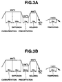
| Examples of the Invention | 1 | A | Fig. 3A | 1.0 | 0.9 | -- | M23C6 | 0.18 |
| 2 | B | Fig. 3A | 1.1 | 1.0 | -- | M23C6 | 0.21 | |
| 3 | C | Fig. 3A | 1.0 | 0.9 | -- | M23C6 | 0.22 | |
| 4 | D | Fig. 3C | 1.4 | 1.2 | -- | M23C6+ M3C | 0.28 | |
| 5 | E | Fig.3A | 1.0 | 0.9 | -- | M23C6 | 0.19 | |
| 6 | F | Fig.3B | 1.1 | 1.0 | -- | M23C6 | 0.25 | |
| 7 | G | Fig.3A | 1.0 | 0.9 | -- | M23C6 | 0.23 | |
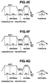
| 8 | A | Fig.4E | 1.0 | 0.9 | -- | M23C6 | 0.21 | |
| 9 | A | Fig.4F | 1.0 | 0.9 | -- | M23C6 | 0.2 | |
| 10 | L | Fig.5H | 1.0 | 1.0 | -- | M23C6 | 0.15 | |
| 11 | M | Fig.5H | 1.3 | 1.3 | -- | M23C6 | 0.17 | |
| 12 | N | Fig.5H | 1.5 | 1.5 | -- | M23C6+ M3C | 0.85 | |
| 13 | O | Fig.5I | 0.8 | 0.8 | -- | M23C6 | 0.22 | |
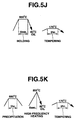
| 14 | P | Fig.5J | 0.6 | 0.6 | -- | M23C6 | 0.16 | |
| 15 | L | Fig.5K | 1.0 | 1.0 | -- | M23C6 | 0.15 | |
| 16 | S | Fig.3A | 1.0 | 0.9 | -- | M23C6 | 0.19 | |
| 17 | T | Fig.3A | 1.0 | 0.9 | -- | M23C6 | 0.12 | |
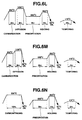
| 18 | A | Fig.6I | 1 | 0.9 | -- | M23C6 | 0.15 | |
| 19 | E | Fig.6M | 0.9 | 0.8 | -- | M23C6 | 0.1 | |
| 20 | F | Fig.6N | 1 | 0.9 | 0.3 | M23C6 | 0.18 | |
| 21 | Q | Fig.5H | 0.4 | 0.4 | -- | M23C6 | 0.19 | |
| 22 | V | Fig.3A | 1.0 | 0.9 | -- | M23C6 | 0.15 | |
| Comparative Examples | 1 | A | Fig.3D | 1.8 | 1.5 | -- | M3C | 3.94 |
| 2 | H | Fig.3C | 1.4 | 1.2 | -- | M3C | 3.54 | |
| 3 | I | Fig.3C | 1.4 | 1.2 | -- | M3C | 3.45 | |
| 4 | J | Fig.3A | 1.0 | 0.9 | -- | M3C | 3.44 | |
| 5 | K | Fig.3A | 1.0 | 0.9 | -- | M3C | 3.23 | |
| 6 | A | Fig.4G | 1.0 | 0.9 | -- | -- | -- | |
| 7 | R | Fig.5H | 1.8 | 0.8 | -- | M3C | 3.78 | |
| 8 | W | Fig.3A | 1.0 | 0.9 | -- | M23C6 | 0.17 |
| Classification | Type of Steel | Precipitate surface area ratio at 0.1 mm (%) | Hardness at 0.1 mm (HV) | 300°C x 3 hr. temper hardness at 0.1 mm (HV) | Thrust test life (L50) (times) | Roller pitting life (times) | |
| Examples of the Invention | 1 | A | 10.5 | 821 | 754 | 9.1 x 10⁷ | Surpassed 107 |
| 2 | B | 6.9 | 819 | 746 | 8.9 x 10⁷ | Surpassed 107 | |
| 3 | C | 3.4 | 825 | 750 | 8.7 x 10⁷ | Surpassed 107 | |
| 4 | D | 15.8 | 820 | 742 | 8.8 x 10⁷ | Surpassed 107 | |
| 5 | E | 7.3 | 816 | 739 | 8.9 x 10⁷ | Surpassed 107 | |
| 6 | F | 17.7 | 817 | 733 | 9.0 x 10⁷ | Surpassed 107 | |
| 7 | G | 12.1 | 822 | 748 | 8.9 x 10⁷ | Surpassed 107 | |
| 8 | A | 25.8 | 841 | 764 | 9.8 x 10⁷ | Surpassed 107 | |
| 9 | A | 0.5 | 825 | 755 | 8.8 x 10⁷ | Surpassed 107 | |
| 10 | L | 12.5 | 815 | 745 | 8.9 x 10⁷ | Surpassed 107 | |
| 11 | M | 25.7 | 829 | 772 | 9.5 x 10⁷ | Surpassed 107 | |
| 12 | N | 8.1 | 786 | 718 | 7.2 x 10⁷ | Surpassed 107 | |
| 13 | 0 | 9.8 | 795 | 733 | 9.1 x 10⁷ | Surpassed 107 | |
| 14 | P | 7.8 | 778 | 714 | 8.4 x 10⁷ | Surpassed 107 | |
| 15 | L | 13.4 | 821 | 732 | 9.2 x 10⁷ | Surpassed 107 | |
| 16 | S | 28.5 | 815 | 752 | 9.7 x 10⁷ | Surpassed 107 | |
| 17 | T | 16.9 | 811 | 745 | 9.2 x 10⁷ | Surpassed 107 | |
| 18 | A | 20.5 | 819 | 756 | 9.8 x 10⁷ | Surpassed 107 | |
| 19 | E | 19.8 | 807 | 749 | 9.7 x 10⁷ | Surpassed 107 | |
| 20 | F | 2.4 | 798 | 737 | 9.8 x 10⁷ | Surpassed 107 | |
| 21 | Q | 0.1 | 742 | 681 | 5.5 x 10⁷ | Surpassed 107 | |
| 22 | V | 0.1 | 721 | 678 | 4.2 x 10⁷ | 6.1x10⁶ | |
| Comparative Examples | 1 | A | 11.1 | 743 | 703 | 3.4 x 10⁷ | 5.4x10⁶ |
| 2 | H | 7.8 | 725 | 673 | 1.1 x 10⁷ | 1.4x10⁶ | |
| 3 | I | 8.2 | 731 | 671 | 1.2 x 10⁷ | 1.5x10⁶ | |
| 4 | J | 4.9 | 715 | 655 | 1.6 x 10⁷ | 2.8x10⁶ | |
| 5 | K | 5.1 | 709 | 649 | 1.5 x 10⁷ | 2.9x10⁶ | |
| 6 | A | -- | 759 | 701 | 4.2 x 10⁷ | 6.2x10⁶ | |
| 7 | R | 8.2 | 785 | 690 | 1.9 x 10⁷ | 2.2x10⁶ | |
| 8 | W | 19.5 | 814 | 739 | 6.2 x 10⁷ | Surpassed 107 |

| Type of test gear | Spiral bevel gear |
| Module | 3.87 |
| Pressure angle | 17.5° |
| Number of teeth | 21 |
| | 15° |
| Standard pitch circle | 84.1 mm |
| Classification | Type of Steel | Heat Treatment | Arc Height (mm) | Pitting Life |
| Invention example 25 (Invention example 1) | A | Fig. 3A | 1.1 | Surpassed 1x10⁷ times |
| Invention example 26 (Invention example 4) | D | Fig. 3C | 0.95 | Surpassed 1x10⁷ times |
| Invention example 27 (Invention example 10) | L | Fig. 5H | 1.02 | Surpassed 1x10⁷ times |
| Invention example 28 (Invention example 19) | E | Fig. 6M | 1.08 | Surpassed 1x10⁷ times |
| Comparative example 13 (Comp. example 1) | A | Fig. 3D | 0.98 | 5.7x10⁶ times |
| Comparative example 14 (Comp. Example 2) | H | Fig. 3C | 1.1 | 1.5x10⁶ times |
| Note) Arc height indicates intensity of shot-peening and corresponds to height of warp of thin sheet under shot-peening. |
| Type of Steel | Chemical Composition (wt%) | T | ||||||||
| C | Si | Mn | P | S | Ni | Cr | Mo | V | ||
| 1A | 0.20 | 0.25 | 0.30 | 0.015 | 0.009 | 1.9 | 2.00 | 0.70 | 0.20 | 784.2 |
| 1B | 0.20 | 0.25 | 0.80 | 0.015 | 0.009 | -- | 1.10 | 0.15 | -- | 770.25 |
| 1C | 1.00 | 0.25 | 0.30 | 0.015 | 0.003 | 2.0 | 2.00 | 0.70 | 0.19 | 785.5 |
| 1D | 0.60 | 1.03 | 0.39 | 0.013 | 0.005 | 2.1 | 2.10 | 1.20 | 0.00 | 1062.9 |
| 1E | 0.40 | 1.00 | 0.35 | 0.015 | 0.006 | 2.0 | 2.00 | 1.50 | 0.20 | 1043.5 |
| 1F | 1.80 | 1.10 | 0.40 | 0.014 | 0.003 | 1.9 | 2.10 | 1.40 | 0.20 | 1039.7 |
| 1G | 0.20 | 1.00 | 0.30 | 0.015 | 0.015 | 2 | 1.50 | 1.50 | 0.20 | 1028.5 |
| Classification | Type of Steel | Heat treatment conditions | Surface carbon density (wt%) | Carbon density at depth of max. shearing stress (wt%) | Base material structure (wt%) | Precipitate structure |
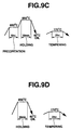
| Invention example 31 | 1A | Fig. 9A | 1.0 | 0.6 | Martensite | M23C6 |
| Invention example 32 | 1C | Fig.9C | 1.0 | 1.0 | Martensite | M23C6 |
| Invention example 33 | 1D | Fig. 9D | 0.6 | 0.6 | Martensite | M23C6 |
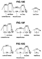
| Invention example 34 | 1A | Fig.10E | 1.1 | 0.7 | Martensite | M23C6 |
| Invention example 35 | 1A | Fig.10F | 1.1 | 0.5 | Martensite | M23C6 |
| Invention example 36 | 1A | Fig.10G | 1.0 | 0.6 | Martensite | M23C6 |
| Invention example 37 | 1E | Fig.9C | 0.4 | 0.4 | Martensite | M23C6 |
| Comparative example 21 | 1B | Fig.9B | 1.1 | 0.7 | Martensite | M3C |
| Comparative example 22 | 1F | Fig.9C | 1.8 | 1.8 | Martensite | M23C6 + M3C |
| Classification | Precipitate mean particle size (µm) | Carbon surface area ratio in 2nd phase (%) | Surface area ratio of 2nd phase (%) | Thrust test life (L50) (times) | Roller pitting life (times) |
| Invention example 31 | 0.25 | 15.8 | 81 | 8.8x10⁷ | Surpassed 107 |
| Invention example 32 | 0.17 | 17.9 | 52 | 8.1x10⁷ | Surpassed 107 |
| Invention example 33 | 0.18 | 12.4 | 22 | 7.2x10⁷ | Surpassed 107 |
| Invention example 34 | 0.16 | 23.1 | 35 | 7.9x10⁷ | Surpassed 107 |
| Invention example 35 | 0.19 | 18.8 | 23 | 8.9x10⁷ | Surpassed 107 |
| Invention example 36 | 0.20 | 20.1 | 19 | 9.1x10⁷ | Surpassed 107 |
| Invention example 37 | 0.19 | 2.0 | 2 | 5.3x10⁶ | Surpassed 107 |
| Comparative example 21 | 3.80 | -- | 0 | 2.1x10⁷ | Surpassed 107 |
| Comparative example 22 | 4.20 | 22.2 | 55 | 3.4x10⁶ | Surpassed 107 |
| Classification | Type of Steel | Heat treatment conditions | site (Figs. 8A,8B) | 2nd phase surface area ratio | Endurance testing | ||
| Shotpeening | Rolling fatigue life | Bending fatigue life | |||||
| Inv. Ex. 38 (Inv. Ex. 31) | 1A | Fig. 9A | A | 81 | No | o ○ | -- |
| B | 73 | No | o ○ | -- | |||
| C | 64 | No | o ○ | -- | |||
| D | 20 | Yes | -- | ○ | |||
| E | 78 | No | o ○ | -- | |||
| | 15 | Yes | -- | ○ | |||
| Inv. Ex. 39 (Inv. Ex. 34) | 1A | Fig. 10C | A | 52 | No | o ○ | -- |
| B | 49 | No | o ○ | -- | |||
| C | 42 | No | o ○ | -- | |||
| D | 12 | Yes | -- | ○ | |||
| E | 45 | No | o ○ | -- | |||
| F | 8 | Yes | -- | ○ | |||
| Inv. Ex. 40 (Inv. Ex. 36) | 1A | Fig. 10G | A | 22 | No | o ○ | -- |
| | 15 | No | o ○ | -- | |||
| | 13 | No | o ○ | -- | |||
| D | 8 | Yes | -- | ○ | |||
| | 16 | No | o ○ | -- | |||
| | 3 | Yes | -- | ○ | |||
| Comp. Ex. 23 (Comp. Ex. 31) | 1B | Fig. 9B | A | 0 | No | ○ | -- |
| B | 0 | No | ○ | -- | |||
| C | 0 | No | ○ | -- | |||
| D | 0 | Yes | -- | ○ | |||
| E | 0 | No | ○ | -- | |||
| F | 0 | Yes | -- | ○ | |||
| Comp. Ex. 24 (Comp. Ex. 32) | 1C | Fig. 9C | A | 55 | No | ○ | -- |
| B | 38 | No | ○ | -- | |||
| C | 34 | No | ○ | -- | |||
| | 16 | Yes | -- | Δ | |||
| E | 39 | No | ○ | -- | |||
| F | 11 | Yes | -- | Δ | |||
| Note) o ○ indicates excellent evaluation; ○ indicates better evaluation; ○ indicates better |
| Classification | Type of Steel | Heat Treatment | Arc Height | Pitting Life |
| Invention example 41 (Invention example 31) | 1A | Fig. 9A | 0.95 | Surpassed 1x10⁷ times |
| Invention example 42 (Invention example 34) | 1A | Fig. 10E | 0.94 | Surpassed 1x10⁷ times |
| Invention example 43 (Invention example 36) | 1A | Fig. 10G | 1.12 | Surpassed 1x10⁷ times |
| Comparative example 25 (Comp. Example 31) | 1B | Fig. 9B | 0.91 | 4.4x10⁶ times |
| Comparative example 26 (Comp. Example 32) | 1F | Fig. 9C | 0.97 | 0.8x10⁶ times |
| Note) Arc height indicates intensity of shot-peening and corresponds to height of warp of thin sheet under shot-peening. |
Claims (31)
- A high bearing pressure-resistant member comprisinga mechanical structural steel containing Cr, said mechanical structural steel including a matrix having at least one of martensite structure and bainite structure, said matrix containing carbide having a mean particle size of 3 µm or less, dispersed and precipitated in form of at least one of generally sphere and pseudo-sphere, said carbide including M23C6-type carbide.
- A high bearing pressure-resistant member as claimed in Claim 1, said mechanical structural steel includes a first phase region having at least one of martensite structure and bainite structure, and a second phase region including a matrix having at least one of martensite structure and bainite structure, said matrix containing carbide having a mean particle size of 3 µm or less, dispersed and precipitated in form of at least one of generally sphere and pseudo-sphere.
- A high bearing pressure-resistant member as claimed in Claim 2, wherein said second phase region includes carbide which contains M23C6-type carbide containing at least Cr, dispersed and precipitated in the second phase region.
- A high bearing pressure-resistant member as claimed in Claim 2, wherein a surface area ratio of the second phase region at a site subjected to rolling fatigue due to rolling contact and sensitive to a surface origin separation is within a range of from 3 to 100% at a uppermost surface of said mechanical structural steel.
- A high bearing pressure-resistant member as claimed in Claim 2, wherein a surface area ratio of the second phase region at a site subjected to rolling fatigue due to rolling contact and sensitive to a surface origin separation is within a range of from 50 to 80% at a uppermost surface of said mechanical structural steel.
- A high bearing-pressure resistant member as claimed in Claim 2, wherein a surface area ratio of the second phase region at a site subjected to bending fatigue by a repetitive load of bending stress is 90% or less at a uppermost surface of said mechanical structural steel, wherein shot-peening is performed at the uppermost surface.
- A high bearing pressure-resistant member as claimed in Claim 6, wherein the surface area ratio of the second phase region at the site subjected to bending fatigue by a repetitive load of bending stress is 30% or less at the uppermost surface of said member, wherein shot-peening is performed at the uppermost surface.
- A high bearing pressure-resistant member as claimed in Claim 2, wherein a surface area of the second phase at the site subjected to rolling fatigue by a repetitive load of shearing stress caused by rolling contact is 3% or more at a surface layer extending from a surface of said material member to a depth location where a maximum shearing stress occurs.
- A high bearing pressure-resistant member as set forth in claim 8, wherein the surface area ratio of the second phase at the site subjected to rolling fatigue by a repetitive load of shearing stress caused by rolling contact is 50% or more at the surface layer extending from the surface of said material member to the depth location where the maximum shearing stress occurs.
- A high bearing pressure-resistant member as claimed in Claim 3, S is contained in an amount of 0.01% by weight or less relative to weight of said mechanical structural steel.
- A high bearing pressure-resistant member as claimed in Claim 3, wherein said carbide is dispersed and precipitated at a surface area ratio ranging from 0.3 to 30% in the second phase region.
- A high bearing pressure-resistant member as claimed in Claim 10, wherein nitrogen is contained in solid solution in an amount ranging from 0.01 to 0.5% by relative to weight of said material member, at least a location from a surface of said high bearing pressure-resistant member formed before grinding to a surface of said high bearing pressure-resistant member formed after grinding.
- A high bearing pressure-resistant member as claimed in Claim 2, wherein said mechanical structural steel contains Cr in an amount ranging from 1.2 to 3.2% by weight and Mo in an amount ranging from 0.25 to 2.0% by weight.
- A high bearing pressure-resistant member as claimed in Claim 13, wherein nitrogen is contained in solid solution in an amount ranging from 0.01 to 0.5% by weight relative to weight of said high bearing pressure-resistant member, at least a location from a surface of said member formed before grinding to a surface of said high bearing pressure-resistant member formed after grinding.
- A high bearing pressure-resistant member as claimed in Claim 13, wherein sulfur is contained in an amount of not more than 0.01 % by relative to weight of said mechanical structural steel.
- A high bearing pressure-resistant member as claimed in Claim 2, wherein said carbide at least at a cross-sectional surface of said mechanical structural steel located at a depth of the occurrence of maximum shearing stress caused by rolling contact is dispersed and precipitated in a surface area ratio ranging from 0.3 to 30%.
- A high bearing pressure-resistant member as claimed in Claim 16, wherein said steel has a surface carbon density at a site subjected to rolling fatigue caused by rolling contact, within a range of from 0.6 to 1.5% by weight.
- A high bearing pressure-resistant member as claimed in Claim 2, wherein a carbon density at a site subjected to rolling fatigue by a repetitive load of shearing stress caused by rolling contact is 0.5% by weight or more.
- A high bearing pressure-resistant member as claimed in Claim 2, wherein said member is a rolling element forming part of a toroidal continuously variable transmission.
- A process of producing a high bearing pressure-resistant member, comprising:performing a carburization treatment on a material member formed of a mechanical structural steel containing Cr so that a surface carbon density of said mechanical structural member is within a range of from 0.6 to 1.5% by weight;precipitating carbide by holding the carburized material member at a precipitation temperature Tp (°C) having an upper limit temperature T (°C) calculated according to a first equation: T = 675 + 120·Si(%) - 27·Ni(%) + 30·Cr(%) + 215·Mo(%) - 400·V(%) based components of the material member for a time shorter than a time t (hr.) calculated according to a second equation: t = 10{19000/Tp + 273) - 20} based on said precipitation temperature Tp (°C); andquenching the carbide-precipitated material member by rapidly cooling the carbide-precipitated member after holding the carbide-precipitated material member at at least one of a Ac1 transformation temperature and a temperature at which austenite phase is formed.
- A process as claimed in Claim 20, wherein said material member contains Cr in an amount ranging from 1.2 to 3.2% by weight and Mo in an amount ranging from 0.25 to 2.0% by weight so as to have a surface carbon density is within a range of from 0.6 to 1.5% by weight, wherein said performing carburization treatment includes setting a carbon density at a site of a depth of occurrence of maximum shearing stress caused by rolling contact, within a range of 0.5% by weight or more.
- A process as claimed in Claim 21, wherein a ratio (Td/Tc) of a diffusion temperature Td (°C) after the carburization treatment to a carburization temperature Tc (°C) during the carburization treatment is within a range of from 1.05 to 1.25.
- A process as claimed in Claim 22, wherein a cooling rate in a transient time from completion of the carburization treatment to said precipitating carbide is 10°C per minute or more.
- A process as claimed in Claim 23, wherein nitriding is performed on said material member simultaneous to or after completion of the carburization treatment.
- A process as claimed in Claim 20, wherein the mechanical structural steel contains Cr and carbon in a range of from 0.6 to 1.5% by weight.
- A process as claimed in Claim 20, wherein the mechanical structural steel contains Cr in an amount ranging from 1.2 to 3.2% by weight, Mo in an amount ranging from 0.25 to 2.0% by weight, and C in an amount ranging from 0.6 to 1.5% by weight.
- A process as claimed in Claim 20, wherein holding the carbide-precipitated material member at at least one of a Ac1 transformation temperature and a temperature at which austenite phase is formed also serves as said precipitating carbide.
- A process of producing a high bearing pressure-resistant member, comprising:performing carburization treatment on a material member formed of a mechanical structural steel containing Cr so that said material member has a surface carbon density within a range of from 0.6 to 1.5% by weight;precipitating carbide by holding the carburized material member at a temperature having an upper limit temperature T (°C) which is calculated from an equation: T = 675 + 120·Si(wt%) - 27·Ni(wt%) + 30·Cr(wt%) + 215·Mo(wt%) - 400·V(wt%); andquenching the carbide-precipitated material member by rapidly cooling the carbide-precipitated member after holding the carbide-precipitated member at a temperature at which austenite phase is formed.
- A process as claimed in Claim 28, wherein said mechanical structural steel contains Cr in an amount ranging from 1.2 to 3.2% by weight, and Mo in an amount ranging from 0.25 to 2.0% by weight, wherein the carburization treatment performing includes causing said material member to have a carbon density of not less than 0.5% by weight at a location of depth of said member where maximum shearing stress occurs caused by rolling contact.
- A process as claimed in Claim 28, wherein said mechanical structural steel contains Cr in an amount ranging from 1.2 to 3.2% by weight, Mo in an amount ranging from 0.25 to 2.0% by weight, and C in an amount ranging from 0.6 to 1.5% by weight.
- A process as claimed in Claim 28, wherein said carburization treatment performing includes nitriding said material member.
Applications Claiming Priority (6)
| Application Number | Priority Date | Filing Date | Title |
|---|---|---|---|
| JP20655299 | 1999-07-21 | ||
| JP20655299 | 1999-07-21 | ||
| JP20895899 | 1999-07-23 | ||
| JP20895899 | 1999-07-23 | ||
| JP2000204798A JP4022607B2 (en) | 1999-07-21 | 2000-07-06 | Manufacturing method of high surface pressure resistant member |
| JP2000204798 | 2000-07-06 |
Publications (3)
| Publication Number | Publication Date |
|---|---|
| EP1070760A2 true EP1070760A2 (en) | 2001-01-24 |
| EP1070760A3 EP1070760A3 (en) | 2004-03-24 |
| EP1070760B1 EP1070760B1 (en) | 2006-08-30 |
Family
ID=27328649
Family Applications (1)
| Application Number | Title | Priority Date | Filing Date |
|---|---|---|---|
| EP00115487A Expired - Lifetime EP1070760B1 (en) | 1999-07-21 | 2000-07-18 | Process of producing a high bearing pressure-resistant member |
Country Status (4)
| Country | Link |
|---|---|
| US (1) | US6569267B1 (en) |
| EP (1) | EP1070760B1 (en) |
| JP (1) | JP4022607B2 (en) |
| DE (1) | DE60030364T2 (en) |
Cited By (24)
| Publication number | Priority date | Publication date | Assignee | Title |
|---|---|---|---|---|
| GB2349647B (en) * | 1998-12-21 | 2003-04-09 | Nsk Ltd | Rolling bearing |
| EP1452755A1 (en) * | 2003-02-28 | 2004-09-01 | NTN Corporation | Differential supported by rolling element bearing with a shaft and gears and a method of manufacturing the rolling elements, the races, the shaft and the gears by hardening including carbonitriding |
| EP1512761A1 (en) * | 2003-08-28 | 2005-03-09 | Nissan Motor Company, Limited | Contact pressure-resistant member and method of making the same |
| WO2005066383A1 (en) * | 2003-12-22 | 2005-07-21 | Caterpillar Inc. | Method for carburizing a steel article and steel article thus obtained with improved wear resistance |
| EP1455102A3 (en) * | 2003-02-28 | 2006-01-18 | NTN Corporation | Transmission component, method of manufacturing the same, and tapered roller bearing |
| WO2006068205A1 (en) | 2004-12-24 | 2006-06-29 | Jtekt Corporation | Rolling-sliding elements and process for production of the same |
| WO2007014642A1 (en) * | 2005-07-30 | 2007-02-08 | Ab Skf | Antifriction mounting |
| EP1258644A3 (en) * | 2001-05-17 | 2008-01-09 | Nissan Motor Company, Limited | Bearing pressure-resistant member and process for making the same |
| US7334943B2 (en) | 2003-02-28 | 2008-02-26 | Ntn Corporation | Differential support structure, differential's component, method of manufacturing differential support structure, and method of manufacturing differential's component |
| US7438477B2 (en) | 2001-11-29 | 2008-10-21 | Ntn Corporation | Bearing part, heat treatment method thereof, and rolling bearing |
| US7490583B2 (en) | 2002-10-17 | 2009-02-17 | Ntn Corporation | Full-type rolling bearing and roller cam follower for engine |
| EP2045339A1 (en) * | 2007-09-20 | 2009-04-08 | Ab Skf | Workpiece for rolling wear stress made of through hardened steel and method of heat treatment |
| EP1156127A3 (en) * | 2000-05-17 | 2009-05-20 | Nissan Motor Company, Limited | Steel for high bearing pressure-resistant member, having high machinability, and high bearing pressure-resistant member using same steel |
| US7594762B2 (en) | 2004-01-09 | 2009-09-29 | Ntn Corporation | Thrust needle roller bearing, support structure receiving thrust load of compressor for car air-conditioner, support structure receiving thrust load of automatic transmission, support structure for continuously variable transmission, and support structure receivin |
| US7641742B2 (en) | 2004-01-15 | 2010-01-05 | Ntn Corporation | Rolling bearing and heat treatment method for steel |
| US7744283B2 (en) | 2003-03-14 | 2010-06-29 | Ntn Corporation | Bearing for alternator and bearing for pulley |
| US8002907B2 (en) | 2003-08-29 | 2011-08-23 | Ntn Corporation | Bearing's component, heat treatment method thereof, heat treatment apparatus, and rolling bearing |
| US8066826B2 (en) | 2005-08-10 | 2011-11-29 | Ntn Corporation | Rolling-contact shaft with joint claw |
| EP2514847A4 (en) * | 2010-03-19 | 2013-08-28 | Nippon Steel & Sumitomo Metal Corp | STEEL FOR CEMENT TREATMENT, CEMENTED STEEL COMPONENT, AND METHOD FOR PRODUCING THE SAME |
| WO2013139576A1 (en) * | 2012-03-22 | 2013-09-26 | Schaeffler Technologies AG & Co. KG | Rolling bearing having a bearing ring with a hardened surface zone |
| WO2013139514A1 (en) * | 2012-03-20 | 2013-09-26 | Aktiebolaget Skf | Method for producing a rolling bearing, and rolling bearing |
| EP3591081A1 (en) * | 2018-07-05 | 2020-01-08 | Deutsche Edelstahlwerke Specialty Steel GmbH & Co. KG | Use of a steel for producing a steel component, namely for a gearwheel, a shaft, an axle or a tool holder to a thermochemically cured edge layer and such steel component having a thermochemically cured edge layer |
| CN111118272A (en) * | 2020-02-12 | 2020-05-08 | 广东省材料与加工研究所 | High-performance 17-4PH stainless steel material and high-pressure heat treatment method, manufacturing method and application thereof |
| EP3705598A4 (en) * | 2017-10-30 | 2020-09-09 | Denso Corporation | CARBURATION PROCESS |
Families Citing this family (22)
| Publication number | Priority date | Publication date | Assignee | Title |
|---|---|---|---|---|
| JP2002339054A (en) * | 2001-05-17 | 2002-11-27 | Daido Steel Co Ltd | High surface pressure resistant member and method of manufacturing the same |
| JP2002356738A (en) * | 2001-05-29 | 2002-12-13 | Daido Steel Co Ltd | High surface pressure resistant member and method of manufacturing the same |
| JP3886350B2 (en) * | 2001-08-30 | 2007-02-28 | Ntn株式会社 | Swash plate compressor |
| JP2003130163A (en) * | 2001-10-19 | 2003-05-08 | Nsk Ltd | Toroidal continuously variable transmission |
| DE10216492B4 (en) * | 2002-04-13 | 2005-07-21 | Ab Skf | Method for producing a roller bearing component made of metal |
| JP4075492B2 (en) | 2002-07-11 | 2008-04-16 | 株式会社ジェイテクト | Method for manufacturing torque transmitting member of toroidal type continuously variable transmission |
| JP4912385B2 (en) * | 2003-03-04 | 2012-04-11 | 株式会社小松製作所 | Manufacturing method of rolling member |
| JP4390576B2 (en) * | 2003-03-04 | 2009-12-24 | 株式会社小松製作所 | Rolling member |
| JP4390526B2 (en) * | 2003-03-11 | 2009-12-24 | 株式会社小松製作所 | Rolling member and manufacturing method thereof |
| JP2005090680A (en) * | 2003-09-19 | 2005-04-07 | Koyo Seiko Co Ltd | Rolling bearing part and method of manufacturing the same |
| JP4576842B2 (en) * | 2004-01-20 | 2010-11-10 | 日本精工株式会社 | Rolling bearing and belt type continuously variable transmission using the same |
| KR20070099534A (en) * | 2004-10-15 | 2007-10-09 | 가부시키가이샤 제이텍트 | Rolling / sliding member, toroidal type continuously variable transmission using same and manufacturing method of rolling / sliding member |
| WO2007010772A1 (en) * | 2005-07-20 | 2007-01-25 | Ntn Corporation | Bearing device for wheel |
| JP2007169673A (en) * | 2005-12-19 | 2007-07-05 | Nsk Ltd | Steel heat treatment method, rolling support device manufacturing method for rolling support device, rolling support device |
| JP4458079B2 (en) * | 2006-09-27 | 2010-04-28 | 株式会社Ihi | Vacuum carburizing equipment |
| JP4458107B2 (en) | 2007-03-09 | 2010-04-28 | 株式会社Ihi | Vacuum carburizing method and vacuum carburizing apparatus |
| JP5153295B2 (en) * | 2007-10-26 | 2013-02-27 | 本田技研工業株式会社 | Carburized parts with excellent fatigue strength |
| JP2010222696A (en) * | 2009-03-25 | 2010-10-07 | Nisshin Steel Co Ltd | Quenched and tempered steel strip, and method for producing the same |
| EP2697407A4 (en) * | 2011-04-13 | 2015-09-30 | Skf Ab | METHOD FOR CARBONITURING A STEEL COMPONENT, STEEL COMPONENT AND USE OF THE COMPONENT |
| JP6572530B2 (en) | 2014-10-17 | 2019-09-11 | 株式会社ジェイテクト | Heat treatment apparatus and heat treatment method |
| JP6507559B2 (en) * | 2014-10-17 | 2019-05-08 | 株式会社ジェイテクト | Bearing bearing ring and rolling bearing |
| WO2023182333A1 (en) * | 2022-03-25 | 2023-09-28 | 日立建機株式会社 | Gear component |
Family Cites Families (9)
| Publication number | Priority date | Publication date | Assignee | Title |
|---|---|---|---|---|
| US4023988A (en) * | 1976-02-02 | 1977-05-17 | Ford Motor Company | Heat treatment for ball bearing steel to improve resistance to rolling contact fatigue |
| DE3800838C1 (en) * | 1988-01-14 | 1989-09-14 | Skf Gmbh, 8720 Schweinfurt, De | |
| JP2779170B2 (en) * | 1988-07-25 | 1998-07-23 | マツダ株式会社 | Carburizing and quenching method |
| EP0688883B1 (en) * | 1993-12-28 | 1999-12-08 | Nippon Steel Corporation | Martensitic heat-resisting steel having excellent resistance to haz softening and process for producing the steel |
| JP3413975B2 (en) * | 1994-08-08 | 2003-06-09 | 日本精工株式会社 | Rolling bearing with excellent wear resistance |
| JPH09256105A (en) * | 1996-03-21 | 1997-09-30 | Sumitomo Metal Ind Ltd | Bearing element component and manufacturing method thereof |
| JP3909902B2 (en) * | 1996-12-17 | 2007-04-25 | 株式会社小松製作所 | Steel parts for high surface pressure resistance and method for producing the same |
| GB2324305B (en) * | 1997-04-16 | 2000-05-24 | Nsk Ltd | Rolling member |
| US5976277A (en) * | 1997-05-08 | 1999-11-02 | Pohang Iron & Steel Co., Ltd. | High speed tool steel, and manufacturing method therefor |
-
2000
- 2000-07-06 JP JP2000204798A patent/JP4022607B2/en not_active Expired - Fee Related
- 2000-07-18 DE DE60030364T patent/DE60030364T2/en not_active Expired - Lifetime
- 2000-07-18 EP EP00115487A patent/EP1070760B1/en not_active Expired - Lifetime
- 2000-07-20 US US09/620,996 patent/US6569267B1/en not_active Expired - Lifetime
Cited By (34)
| Publication number | Priority date | Publication date | Assignee | Title |
|---|---|---|---|---|
| GB2349647B (en) * | 1998-12-21 | 2003-04-09 | Nsk Ltd | Rolling bearing |
| EP1156127A3 (en) * | 2000-05-17 | 2009-05-20 | Nissan Motor Company, Limited | Steel for high bearing pressure-resistant member, having high machinability, and high bearing pressure-resistant member using same steel |
| EP1258644A3 (en) * | 2001-05-17 | 2008-01-09 | Nissan Motor Company, Limited | Bearing pressure-resistant member and process for making the same |
| US8425690B2 (en) | 2001-11-29 | 2013-04-23 | Ntn Corporation | Bearing part, heat treatment method thereof, and rolling bearing |
| US7438477B2 (en) | 2001-11-29 | 2008-10-21 | Ntn Corporation | Bearing part, heat treatment method thereof, and rolling bearing |
| US7490583B2 (en) | 2002-10-17 | 2009-02-17 | Ntn Corporation | Full-type rolling bearing and roller cam follower for engine |
| EP1452755A1 (en) * | 2003-02-28 | 2004-09-01 | NTN Corporation | Differential supported by rolling element bearing with a shaft and gears and a method of manufacturing the rolling elements, the races, the shaft and the gears by hardening including carbonitriding |
| EP1455102A3 (en) * | 2003-02-28 | 2006-01-18 | NTN Corporation | Transmission component, method of manufacturing the same, and tapered roller bearing |
| US7334943B2 (en) | 2003-02-28 | 2008-02-26 | Ntn Corporation | Differential support structure, differential's component, method of manufacturing differential support structure, and method of manufacturing differential's component |
| EP1985724A3 (en) * | 2003-02-28 | 2008-11-19 | NTN Corporation | Transmission component, method of manufacturing the same, and tapered roller bearing |
| US7682087B2 (en) | 2003-02-28 | 2010-03-23 | Ntn Corporation | Transmission component, method of manufacturing the same, and tapered roller bearing |
| US8783961B2 (en) | 2003-03-14 | 2014-07-22 | Ntn Corporation | Bearing for alternator and bearing for pulley |
| US7744283B2 (en) | 2003-03-14 | 2010-06-29 | Ntn Corporation | Bearing for alternator and bearing for pulley |
| US8333516B2 (en) | 2003-03-14 | 2012-12-18 | Ntn Corporation | Bearing for alternator and bearing for pulley |
| EP1512761A1 (en) * | 2003-08-28 | 2005-03-09 | Nissan Motor Company, Limited | Contact pressure-resistant member and method of making the same |
| US8002907B2 (en) | 2003-08-29 | 2011-08-23 | Ntn Corporation | Bearing's component, heat treatment method thereof, heat treatment apparatus, and rolling bearing |
| US7169238B2 (en) | 2003-12-22 | 2007-01-30 | Caterpillar Inc | Carbide method and article for hard finishing resulting in improved wear resistance |
| WO2005066383A1 (en) * | 2003-12-22 | 2005-07-21 | Caterpillar Inc. | Method for carburizing a steel article and steel article thus obtained with improved wear resistance |
| US7594762B2 (en) | 2004-01-09 | 2009-09-29 | Ntn Corporation | Thrust needle roller bearing, support structure receiving thrust load of compressor for car air-conditioner, support structure receiving thrust load of automatic transmission, support structure for continuously variable transmission, and support structure receivin |
| US7641742B2 (en) | 2004-01-15 | 2010-01-05 | Ntn Corporation | Rolling bearing and heat treatment method for steel |
| EP1837413A4 (en) * | 2004-12-24 | 2010-07-21 | Jtekt Corp | Rolling-sliding elements and process for production of the same |
| WO2006068205A1 (en) | 2004-12-24 | 2006-06-29 | Jtekt Corporation | Rolling-sliding elements and process for production of the same |
| WO2007014642A1 (en) * | 2005-07-30 | 2007-02-08 | Ab Skf | Antifriction mounting |
| US8066826B2 (en) | 2005-08-10 | 2011-11-29 | Ntn Corporation | Rolling-contact shaft with joint claw |
| EP2045339A1 (en) * | 2007-09-20 | 2009-04-08 | Ab Skf | Workpiece for rolling wear stress made of through hardened steel and method of heat treatment |
| EP2514847A4 (en) * | 2010-03-19 | 2013-08-28 | Nippon Steel & Sumitomo Metal Corp | STEEL FOR CEMENT TREATMENT, CEMENTED STEEL COMPONENT, AND METHOD FOR PRODUCING THE SAME |
| WO2013139514A1 (en) * | 2012-03-20 | 2013-09-26 | Aktiebolaget Skf | Method for producing a rolling bearing, and rolling bearing |
| WO2013139576A1 (en) * | 2012-03-22 | 2013-09-26 | Schaeffler Technologies AG & Co. KG | Rolling bearing having a bearing ring with a hardened surface zone |
| CN104160166A (en) * | 2012-03-22 | 2014-11-19 | 舍弗勒技术有限两合公司 | Rolling bearing having a bearing ring with a hardened surface zone |
| US9239080B2 (en) | 2012-03-22 | 2016-01-19 | Schaeffler Technologies AG & Co. KG | Rolling bearing having a bearing ring with a hardened surface zone |
| CN104160166B (en) * | 2012-03-22 | 2017-04-26 | 舍弗勒技术股份两合公司 | Rolling bearings with bearing rings with hardened edge regions |
| EP3705598A4 (en) * | 2017-10-30 | 2020-09-09 | Denso Corporation | CARBURATION PROCESS |
| EP3591081A1 (en) * | 2018-07-05 | 2020-01-08 | Deutsche Edelstahlwerke Specialty Steel GmbH & Co. KG | Use of a steel for producing a steel component, namely for a gearwheel, a shaft, an axle or a tool holder to a thermochemically cured edge layer and such steel component having a thermochemically cured edge layer |
| CN111118272A (en) * | 2020-02-12 | 2020-05-08 | 广东省材料与加工研究所 | High-performance 17-4PH stainless steel material and high-pressure heat treatment method, manufacturing method and application thereof |
Also Published As
| Publication number | Publication date |
|---|---|
| EP1070760A3 (en) | 2004-03-24 |
| US6569267B1 (en) | 2003-05-27 |
| DE60030364T2 (en) | 2007-08-30 |
| EP1070760B1 (en) | 2006-08-30 |
| DE60030364D1 (en) | 2006-10-12 |
| JP2001098343A (en) | 2001-04-10 |
| JP4022607B2 (en) | 2007-12-19 |
Similar Documents
| Publication | Publication Date | Title |
|---|---|---|
| US6569267B1 (en) | High bearing pressure-resistant member | |
| KR100504705B1 (en) | High internal pressure steel parts and manufacturing method | |
| CN102770567B (en) | Carburized steel member and method for producing same | |
| US7641747B2 (en) | Rolling member and producing method thereof | |
| EP1512761A1 (en) | Contact pressure-resistant member and method of making the same | |
| JPH0826446B2 (en) | Rolling bearing | |
| JP3128803B2 (en) | Rolling bearing | |
| JP7095117B2 (en) | Carburized nitriding bearing parts | |
| JPH0578814A (en) | Rolling bearing | |
| EP1550736A1 (en) | Carburized and quenched member and method for production thereof | |
| US20050247377A1 (en) | Rolling elements | |
| EP1258644A2 (en) | Bearing pressure-resistant member and process for making the same | |
| JP5886119B2 (en) | Case-hardened steel | |
| US5415705A (en) | Rolling bearing | |
| JP4000616B2 (en) | Gear having excellent pitting resistance and method for producing the same | |
| JP2007297676A (en) | Shaft manufacturing method and shaft obtained by this method | |
| JP2024034952A (en) | Steel materials and steel parts for nitriding induction hardening | |
| EP1701052B1 (en) | Rolling bearing | |
| JP2011168820A (en) | Steel product having carbo-nitrided layer and method for producing the same | |
| JP2021006659A (en) | Steel parts and their manufacturing methods | |
| US12534793B2 (en) | Method of heat treating a steel component | |
| JP4821582B2 (en) | Steel for vacuum carburized gear | |
| JP3607583B2 (en) | Steel for power transmission parts and power transmission parts | |
| JP2024108521A (en) | Steel parts | |
| JP2026033923A (en) | Machine structural parts |
Legal Events
| Date | Code | Title | Description |
|---|---|---|---|
| PUAI | Public reference made under article 153(3) epc to a published international application that has entered the european phase |
Free format text: ORIGINAL CODE: 0009012 |
|
| 17P | Request for examination filed |
Effective date: 20000718 |
|
| AK | Designated contracting states |
Kind code of ref document: A2 Designated state(s): AT BE CH CY DE DK ES FI FR GB GR IE IT LI LU MC NL PT SE |
|
| AX | Request for extension of the european patent |
Free format text: AL;LT;LV;MK;RO;SI |
|
| PUAL | Search report despatched |
Free format text: ORIGINAL CODE: 0009013 |
|
| RIC1 | Information provided on ipc code assigned before grant |
Ipc: 7C 23C 8/22 B Ipc: 7C 23C 8/80 B Ipc: 7C 21D 6/00 B Ipc: 7C 21D 9/36 A Ipc: 7C 21D 1/78 B |
|
| AK | Designated contracting states |
Kind code of ref document: A3 Designated state(s): AT BE CH CY DE DK ES FI FR GB GR IE IT LI LU MC NL PT SE |
|
| AX | Request for extension of the european patent |
Extension state: AL LT LV MK RO SI |
|
| 17Q | First examination report despatched |
Effective date: 20041102 |
|
| AKX | Designation fees paid |
Designated state(s): DE FR GB |
|
| GRAP | Despatch of communication of intention to grant a patent |
Free format text: ORIGINAL CODE: EPIDOSNIGR1 |
|
| RTI1 | Title (correction) |
Free format text: PROCESS OF PRODUCING A HIGH BEARING PRESSURE-RESISTANT MEMBER |
|
| GRAS | Grant fee paid |
Free format text: ORIGINAL CODE: EPIDOSNIGR3 |
|
| GRAA | (expected) grant |
Free format text: ORIGINAL CODE: 0009210 |
|
| AK | Designated contracting states |
Kind code of ref document: B1 Designated state(s): DE FR GB |
|
| REG | Reference to a national code |
Ref country code: GB Ref legal event code: FG4D |
|
| REF | Corresponds to: |
Ref document number: 60030364 Country of ref document: DE Date of ref document: 20061012 Kind code of ref document: P |
|
| ET | Fr: translation filed | ||
| PLBE | No opposition filed within time limit |
Free format text: ORIGINAL CODE: 0009261 |
|
| STAA | Information on the status of an ep patent application or granted ep patent |
Free format text: STATUS: NO OPPOSITION FILED WITHIN TIME LIMIT |
|
| 26N | No opposition filed |
Effective date: 20070531 |
|
| REG | Reference to a national code |
Ref country code: FR Ref legal event code: PLFP Year of fee payment: 17 |
|
| REG | Reference to a national code |
Ref country code: FR Ref legal event code: PLFP Year of fee payment: 18 |
|
| REG | Reference to a national code |
Ref country code: FR Ref legal event code: PLFP Year of fee payment: 19 |
|
| PGFP | Annual fee paid to national office [announced via postgrant information from national office to epo] |
Ref country code: FR Payment date: 20190619 Year of fee payment: 20 |
|
| PGFP | Annual fee paid to national office [announced via postgrant information from national office to epo] |
Ref country code: DE Payment date: 20190702 Year of fee payment: 20 |
|
| PGFP | Annual fee paid to national office [announced via postgrant information from national office to epo] |
Ref country code: GB Payment date: 20190717 Year of fee payment: 20 |
|
| REG | Reference to a national code |
Ref country code: DE Ref legal event code: R071 Ref document number: 60030364 Country of ref document: DE |
|
| REG | Reference to a national code |
Ref country code: GB Ref legal event code: PE20 Expiry date: 20200717 |
|
| PG25 | Lapsed in a contracting state [announced via postgrant information from national office to epo] |
Ref country code: GB Free format text: LAPSE BECAUSE OF EXPIRATION OF PROTECTION Effective date: 20200717 |