EP1069806B1 - Defrosting using a microwave oven - Google Patents
Defrosting using a microwave oven Download PDFInfo
- Publication number
- EP1069806B1 EP1069806B1 EP99308600A EP99308600A EP1069806B1 EP 1069806 B1 EP1069806 B1 EP 1069806B1 EP 99308600 A EP99308600 A EP 99308600A EP 99308600 A EP99308600 A EP 99308600A EP 1069806 B1 EP1069806 B1 EP 1069806B1
- Authority
- EP
- European Patent Office
- Prior art keywords
- value
- surface temperature
- food item
- food
- microwave energy
- Prior art date
- Legal status (The legal status is an assumption and is not a legal conclusion. Google has not performed a legal analysis and makes no representation as to the accuracy of the status listed.)
- Expired - Lifetime
Links
Images


Classifications
-
- F—MECHANICAL ENGINEERING; LIGHTING; HEATING; WEAPONS; BLASTING
- F24—HEATING; RANGES; VENTILATING
- F24C—DOMESTIC STOVES OR RANGES ; DETAILS OF DOMESTIC STOVES OR RANGES, OF GENERAL APPLICATION
- F24C7/00—Stoves or ranges heated by electric energy
- F24C7/02—Stoves or ranges heated by electric energy using microwaves
-
- H—ELECTRICITY
- H05—ELECTRIC TECHNIQUES NOT OTHERWISE PROVIDED FOR
- H05B—ELECTRIC HEATING; ELECTRIC LIGHT SOURCES NOT OTHERWISE PROVIDED FOR; CIRCUIT ARRANGEMENTS FOR ELECTRIC LIGHT SOURCES, IN GENERAL
- H05B6/00—Heating by electric, magnetic or electromagnetic fields
- H05B6/64—Heating using microwaves
- H05B6/6447—Method of operation or details of the microwave heating apparatus related to the use of detectors or sensors
- H05B6/645—Method of operation or details of the microwave heating apparatus related to the use of detectors or sensors using temperature sensors
- H05B6/6455—Method of operation or details of the microwave heating apparatus related to the use of detectors or sensors using temperature sensors the sensors being infrared detectors
Definitions
- the present invention relates to a method of defrosting using a microwave oven, comprising applying microwave energy to a food item, preferably by means of a magnetron, while monitoring the surface temperature of the food item by sensing means, preferably infrared sensing means and to a microwave oven comprising a food receiving area, means for applying microwave energy to items in said area, sensing means for detecting the surface temperature of a food item in said area and control means for controlling defrosting of food items in said area.
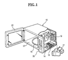
- the microwave oven includes a body 10 and cooking and electrical component chambers 12, 14 within the body 10. Food to be cooked is placed in the cooking chamber 12. A door 20 is provided for opening and closing the cooking chamber 12. A turntable 16 is located at the bottom of the cooking chamber 12.
- the electrical component chamber 14 includes various devices for generating and emitting microwaves to the cooking chamber 12, including a magnetron 17, a high-voltage transformer 18, a waveguide (not shown) and a cooking fan 19.
- a control panel 30 is mounted at the front of the electrical component chamber 14.
- the control panel 30 enables a user to input instructions into the oven. Food is cooked in accordance with the instruction input using the control panel 30 by a control part (not shown) which is formed at the back of the operation panel 30.
- the microwaves generated by the magnetron 17 are guided through the waveguide into the cooking chamber 12.
- the microwaves either irradiate the food directly or after being reflected from the walls of the cooking chamber 12.
- microwave ovens can be used for defrosting frozen food and for warming drinks.
- the frozen food is initially weighed (Step S1) using a weight sensor in the oven.
- Alternative prior art methods require the user to input the weight using the control panel 30.
- a defrosting time is set in dependence on the measured weight of the food (Step S2).
- the magnetron 17, or other microwave generator is operated for the defrosting time (Step S3).
- the magnetron 17 is stopped and the defrosting process is complete (Step S5).
- a method of defrosting using a microwave oven is characterised by initially setting a defrost completion value in dependence on the initial output of the sensing means, and the application of microwave energy being performed until the output of the sensing means, preferably detected regularly, reaches the defrost completion value.
- the initial value is set on the basis of the lowest value obtained while rotating the food item on a turntable.
- the magnetron is driven such that the difference between the initial value and the defrost completion value is divided into at least two divisions, and the power level of the magnetron is varied in accordance with the respective divisions. More preferably, the power level of the magnetron of the respective divisions, is decreased from the value which is closer to the initial value to the value which is closer to the completion value.
- the output value of the sensing means is detected regularly while rotating the food item on a turntable, and the current surface temperature is determined using the lowest output value of the sensing means from a number of output values.
- the defrost completion value is set independently of the weight of the food item.
- the problem of the conventional defrosting method in which, usually, the user places the food to be defrosted on a plate or in a bowl to catch the water that emerges during defrosting and the weight of the plate or bowl is included in the measured weight, making the calculated defrosting time incorrect, is overcome.
- the surface temperature of the food item is determined by scanning a food receiving area containing the food item with an infrared sensor and selecting the lowest temperature detected.
- the food receiving area is the upper surface of a turntable and the infrared sensor has a fixed field of view.
- the microwave energy is applied at reducing levels until the defrost completion value is reached.
- the difference between the initial value and the defrost completion value is divided into a plurality of temperature bands and the microwave energy is applied at different respective levels in dependence on the band into which the detected surface temperature of the food item falls during the application of microwave energy thereto.
- a microwave oven is characterised in that the control means is responsive to the output of said sensing means to set a defrost completion surface temperature in dependence on an initial surface temperature and is configured to apply microwave energy, while monitoring the food item's surface temperature, until said target surface temperature is reached.
- the sensing means is an infrared sensor means.
- control means is configured to set said defrost completion temperature independently of the weight of the food item.
- scanning means are included for scanning said area with the infrared sensor means, wherein the control means selects the lowest temperature detected during scanning by the scanning means as the surface temperature of the food item.
- the scanning means comprises a turntable having said area on its upper surface and the infrared sensor has a fixed field of view.
- control means controls the means for applying microwave energy such that the microwave energy is applied at reducing levels until the defrost completion temperature is reached. More preferably, the control means is configured to divide the difference between the initial surface temperature and the defrost completion temperature into a plurality of temperature bands and control the means for applying microwave energy to apply microwave energy at different respective levels in dependence on the band into which the detected surface temperature of the food item falls during the application of microwave energy thereto.
- an infrared sensor 106 is located at an upper front position relative to a cooking chamber 102 of a microwave oven, in order to detect the surface temperature of the food F placed within a detection spot Sp (See Figure 5) occupying a predetermined area of a turntable 104.
- a driving motor 108 for rotating the turntable 104 is located under the cooking chamber 102 and a door 110 is provided for opening and closing the cooking chamber 102.
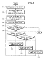
- an initial value Ts detected by the infrared sensor 106 is established (Step S11).
- the initial value Ts obtained in S11 corresponds to the initial surface temperature of the frozen food F.
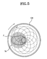
- the infrared sensor 106 outputs a voltage signal corresponding to the average temperature of the area occupied by the detection spot Sp. Accordingly, the voltage signal varies in dependence on the size of the frozen food F and the position of the frozen food F with respect to the turntable 104. More specifically, when the frozen food F is small and off-centre with respect to the turntable 104, as shown in Figure 5, the food F and part of the upper surface of the turntable 104 are simultaneously occupied by the detection spots Sp. In such a situation, the output value of the infrared sensor 106 corresponds to the average temperature of the surface temperature of the food F and the temperature of the upper side of the turntable 104.
- the problem is that the surface temperature of the food F (-20°C to -5°C in general) and the temperature of the upper side of the turntable 104 (at least room temperature) have a wide gap between them. Accordingly, the output of the infrared sensor 106 does not accurately reflect the actual surface temperature of the food F. However, the larger the area of the detection spot Sp occupied by the food F, the more accurate is the output value of the infrared sensor 106.
- the detection spots Sp of the infrared sensor 106 is made to occupy a certain area of the upper surface of the turntable 104, and the output value of the infrared sensor 106 is detected for a predetermined time period while the turntable 104, e.g. twice, and detected on a regular basis such as every second or every two seconds. Then the lowest output value of the infrared sensor 106 is determined to be the correct initial value for the infrared sensor 106.
- the detection spot Sp When the detection spot Sp is made to occupy a certain predetermined area of the upper surface of the turntable 104, the detection spot Sp is scanned circularly across the upper surface of the turntable 104 as it is rotated. Accordingly, as the detection spot Sp scans the turntable 104, the food F and the surface of the turntable 104 are sensed by the detection spots Sp in different proportions.
- the output value of the infrared sensor 106 which is obtained when the largest area of food F is covered by the detection spot Sp, is closest to the actual initial surface temperature of the food.
- the average temperature becomes lower when a greater as the area of food increases. As the average temperature becomes lower, the output value of the infrared sensor 106 becomes lower.
- the lowest value of the output values of the infrared sensor 106 is the closest value with respect to the actual initial surface temperature of the food F.
- the completion value Te is determined to determine the time when the defrosting process is completed (Step S12).
- the completion values Te are pre-stored in the memory, which is employed in the control part for controlling the operation of the microwave oven.
- Table 1 shows the respective completion values Te varying in in dependence on the initial values Ts established using the infrared sensor 106.
- Initial output value Ts of infrared sensor (arbirary units) 59-60 61 62 63-64 65-66 67-68
- Completion value Te of infrared sensor (arbitrary units) 69 70 71 72 73
- Power rate for divisions D1 (40%) 59, 60-62 61-63 62-64 63, 64-65 65, 66-67 67, 68-69 D2 (20%) 63-66 64-66 65-67 66-68 68-69 70-71 D3 (10%) 66-68 67-69 68-70 69-71 70-72 72-73
- the initial value Ts of the infrared sensor 106 ranges from 59 to 68, corresponding to a surface temperature of the food F approximately in the range -20°C to -2°C.
- the corresponding completion value Te ranges from 69 to 74, corresponding to the defrost completion temperature, approximately in the range 0°C to 10°C.
- the completion value Te varies depending on the initial values Ts. This is to prevent the incomplete defrosting of food F due to too short a defrosting time. If the completion value Te is uniformly set, the defrosting time may be shortened when the initial value Ts has a narrow gap with the completion value Te.
- the output value of the infrared sensor 106 corresponding to the temperature of the food F may be varied depending on the types of the infrared sensor 106.
- the magnetron is driven while the current value (Tc) of the infrared sensor 106 output, which corresponds to the surface temperature of the food F, is detected on a regular basis, until the Tc reaches the completion value Te.
- the gap between the initial value Ts and the completion value Te is divided into three divisions, D1, D2, and D3.
- the ranges of the three divisions D1, D2, and D3 are pre-stored in the memory of the controlling part.
- the ranges of the three divisions D1, D2, and D3 are determined by reading those that correspond to the initial value Ts from the memory of the control part.
- the current value Tc is detected (Step S14).
- the current value Tc is detected by the same method that is employed for detecting the initial value Ts in S11.
- a difference lies in that the current value Tc is preferably obtained by detecting the output value of the infrared sensor 106 on a predetermined time basis during the time in which the turntable 104 is rotated once, while the initial value Ts is preferably obtained by detecting the output value of the infrared sensor 106 for a predetermined time period.
- the current value Tc is compared with the completion value Te.
- the power level of the magnetron is set to 40% of maximum (Step S17).
- the power level of the magnetron is set to 20%, or 10%, respectively (Steps S18 and S19).
- the power levels of the magnetron are averages and expressed as percentages to indicate the time when the magnetron is actually driven in a predetermined time period. More specifically, the power level 40%, for example, means that the magnetron is driven periodically for 40% of the unit time period and not driven for 60% of the unit time period.
- the power rate of the magnetron is adjusted from 40% in the division D1, to 20% in the division D2, and to 10% in the division D3, sequentially.
- the current value Tc which is compared with the completion value Te in S15, is equal to or greater than the completion value Te, it is determined that the defrosting process is completed, so that the process exits the loop and the operation for defrosting process such as driving the magnetron, etc is stopped.
- the power of the magnetron is set at 40%, 20%, and 10% for the three divisions D1, D2, and D3, respectively, it is not limited to this case only, but can be varied only if the power rate of the magnetron is decreased as the current value Tc gets closer to the completion value Te from the initial value Ts.
- the defrosting method controls the defrosting process through the output value of the infrared sensor 106, which corresponds to the surface temperature of the food F, the accurate defrost can be performed regardless of the frozen degree of the food F and presence/absence of the receptacle for food F.
Landscapes
- Physics & Mathematics (AREA)
- Electromagnetism (AREA)
- Engineering & Computer Science (AREA)
- Chemical & Material Sciences (AREA)
- Combustion & Propulsion (AREA)
- Mechanical Engineering (AREA)
- General Engineering & Computer Science (AREA)
- Electric Ovens (AREA)
- Control Of High-Frequency Heating Circuits (AREA)
Description
- The present invention relates to a method of defrosting using a microwave oven, comprising applying microwave energy to a food item, preferably by means of a magnetron, while monitoring the surface temperature of the food item by sensing means, preferably infrared sensing means and to a microwave oven comprising a food receiving area, means for applying microwave energy to items in said area, sensing means for detecting the surface temperature of a food item in said area and control means for controlling defrosting of food items in said area.
- A conventional microwave oven is shown in Figure 1. Referring to Figure 1, the microwave oven includes a
body 10 and cooking andelectrical component chambers body 10. Food to be cooked is placed in thecooking chamber 12. Adoor 20 is provided for opening and closing thecooking chamber 12. Aturntable 16 is located at the bottom of thecooking chamber 12. Theelectrical component chamber 14 includes various devices for generating and emitting microwaves to thecooking chamber 12, including amagnetron 17, a high-voltage transformer 18, a waveguide (not shown) and acooking fan 19. - A
control panel 30 is mounted at the front of theelectrical component chamber 14. Thecontrol panel 30 enables a user to input instructions into the oven. Food is cooked in accordance with the instruction input using thecontrol panel 30 by a control part (not shown) which is formed at the back of theoperation panel 30. - When the devices in the
electrical component chamber 14 are operated, the microwaves generated by themagnetron 17 are guided through the waveguide into thecooking chamber 12. The microwaves either irradiate the food directly or after being reflected from the walls of thecooking chamber 12. - In addition to cooking, microwave ovens can be used for defrosting frozen food and for warming drinks.
- A conventional method for defrosting food will now be described with reference to Figure 2.
- Referring to Figure 2, the frozen food is initially weighed (Step S1) using a weight sensor in the oven. Alternative prior art methods require the user to input the weight using the
control panel 30. After weighing of the food, a defrosting time is set in dependence on the measured weight of the food (Step S2). Next, themagnetron 17, or other microwave generator, is operated for the defrosting time (Step S3). When the defrosting time has elapsed (Step S4), themagnetron 17 is stopped and the defrosting process is complete (Step S5). - The reader is also referred to US-A-4401884 for additional background information.
- A method of defrosting using a microwave oven, according to the present invention, is characterised by initially setting a defrost completion value in dependence on the initial output of the sensing means, and the application of microwave energy being performed until the output of the sensing means, preferably detected regularly, reaches the defrost completion value. Thus the problem of the conventional defrosting method using a microwave oven, in which no allowance is made for different initial temperatures of the food to be defrosted, is overcome.
- Preferably, the initial value is set on the basis of the lowest value obtained while rotating the food item on a turntable.
- Preferably, the magnetron is driven such that the difference between the initial value and the defrost completion value is divided into at least two divisions, and the power level of the magnetron is varied in accordance with the respective divisions. More preferably, the power level of the magnetron of the respective divisions, is decreased from the value which is closer to the initial value to the value which is closer to the completion value.
- Preferably, the output value of the sensing means is detected regularly while rotating the food item on a turntable, and the current surface temperature is determined using the lowest output value of the sensing means from a number of output values.
- Preferably, the defrost completion value is set independently of the weight of the food item. Thus, the problem of the conventional defrosting method in which, usually, the user places the food to be defrosted on a plate or in a bowl to catch the water that emerges during defrosting and the weight of the plate or bowl is included in the measured weight, making the calculated defrosting time incorrect, is overcome. More preferably, the surface temperature of the food item is determined by scanning a food receiving area containing the food item with an infrared sensor and selecting the lowest temperature detected. Still more preferably, the food receiving area is the upper surface of a turntable and the infrared sensor has a fixed field of view.
- Preferably, the microwave energy is applied at reducing levels until the defrost completion value is reached.
- Preferably, the difference between the initial value and the defrost completion value is divided into a plurality of temperature bands and the microwave energy is applied at different respective levels in dependence on the band into which the detected surface temperature of the food item falls during the application of microwave energy thereto.
- A microwave oven, according to the present invention, is characterised in that the control means is responsive to the output of said sensing means to set a defrost completion surface temperature in dependence on an initial surface temperature and is configured to apply microwave energy, while monitoring the food item's surface temperature, until said target surface temperature is reached. Preferably, the sensing means is an infrared sensor means.
- Preferably, the control means is configured to set said defrost completion temperature independently of the weight of the food item.
- Preferably, scanning means are included for scanning said area with the infrared sensor means, wherein the control means selects the lowest temperature detected during scanning by the scanning means as the surface temperature of the food item. More preferably, the scanning means comprises a turntable having said area on its upper surface and the infrared sensor has a fixed field of view.
- Preferably, the control means controls the means for applying microwave energy such that the microwave energy is applied at reducing levels until the defrost completion temperature is reached. More preferably, the control means is configured to divide the difference between the initial surface temperature and the defrost completion temperature into a plurality of temperature bands and control the means for applying microwave energy to apply microwave energy at different respective levels in dependence on the band into which the detected surface temperature of the food item falls during the application of microwave energy thereto.
- An embodiment of the present invention will now be described, by way of example, with reference to Figures 3, 4 and 5 of the accompanying drawings, in which: -
- Figure 1 is a perspective view of a conventional microwave oven;
- Figure 2 is a flow chart illustrating a conventional defrosting method;
- Figure 3 is a flow chart illustrating a defrosting method of a microwave oven according to the present invention;
- Figure 4 is a sectional view of a microwave oven according to the present invention; and
- Figure 5 is a plan view of the turntable of the oven of Figure 4.
-
- Referring to Figure 4, an
infrared sensor 106 is located at an upper front position relative to acooking chamber 102 of a microwave oven, in order to detect the surface temperature of the food F placed within a detection spot Sp (See Figure 5) occupying a predetermined area of aturntable 104. - A
driving motor 108 for rotating theturntable 104 is located under thecooking chamber 102 and adoor 110 is provided for opening and closing thecooking chamber 102. - A defrosting method employing the microwave oven of Figure 4 will now be described.
- Referring to Figure 3, an initial value Ts detected by the
infrared sensor 106 is established (Step S11). The initial value Ts obtained in S11 corresponds to the initial surface temperature of the frozen food F. Theinfrared sensor 106 outputs a voltage signal corresponding to the average temperature of the area occupied by the detection spot Sp. Accordingly, the voltage signal varies in dependence on the size of the frozen food F and the position of the frozen food F with respect to theturntable 104. More specifically, when the frozen food F is small and off-centre with respect to theturntable 104, as shown in Figure 5, the food F and part of the upper surface of theturntable 104 are simultaneously occupied by the detection spots Sp. In such a situation, the output value of theinfrared sensor 106 corresponds to the average temperature of the surface temperature of the food F and the temperature of the upper side of theturntable 104. - The problem is that the surface temperature of the food F (-20°C to -5°C in general) and the temperature of the upper side of the turntable 104 (at least room temperature) have a wide gap between them. Accordingly, the output of the
infrared sensor 106 does not accurately reflect the actual surface temperature of the food F. However, the larger the area of the detection spot Sp occupied by the food F, the more accurate is the output value of theinfrared sensor 106. - The detection spots Sp of the
infrared sensor 106 is made to occupy a certain area of the upper surface of theturntable 104, and the output value of theinfrared sensor 106 is detected for a predetermined time period while theturntable 104, e.g. twice, and detected on a regular basis such as every second or every two seconds. Then the lowest output value of theinfrared sensor 106 is determined to be the correct initial value for theinfrared sensor 106. - When the detection spot Sp is made to occupy a certain predetermined area of the upper surface of the
turntable 104, the detection spot Sp is scanned circularly across the upper surface of theturntable 104 as it is rotated. Accordingly, as the detection spot Sp scans theturntable 104, the food F and the surface of theturntable 104 are sensed by the detection spots Sp in different proportions. The output value of theinfrared sensor 106, which is obtained when the largest area of food F is covered by the detection spot Sp, is closest to the actual initial surface temperature of the food. - Further, since the temperature of the upper surface of the
turntable 104 is higher than the surface temperature of the food F, the average temperature becomes lower when a greater as the area of food increases. As the average temperature becomes lower, the output value of theinfrared sensor 106 becomes lower. - Accordingly, the lowest value of the output values of the
infrared sensor 106 is the closest value with respect to the actual initial surface temperature of the food F. - After determining the initial value Ts of the
infrared sensor 106, the completion value Te is determined to determine the time when the defrosting process is completed (Step S12). - The completion values Te are pre-stored in the memory, which is employed in the control part for controlling the operation of the microwave oven. Table 1 below shows the respective completion values Te varying in in dependence on the initial values Ts established using the
infrared sensor 106.Initial output value Ts of infrared sensor (arbirary units) 59-60 61 62 63-64 65-66 67-68 Completion value Te of infrared sensor (arbitrary units) 69 70 71 72 73 74 Power rate for divisions D1 (40%) 59,
60-6261-63 62-64 63,
64-6565,
66-6767,
68-69D2 (20%) 63-66 64-66 65-67 66-68 68-69 70-71 D3 (10%) 66-68 67-69 68-70 69-71 70-72 72-73 - As shown in Table 1, the initial value Ts of the
infrared sensor 106 ranges from 59 to 68, corresponding to a surface temperature of the food F approximately in the range -20°C to -2°C. The corresponding completion value Te ranges from 69 to 74, corresponding to the defrost completion temperature, approximately in the range 0°C to 10°C. - As described above, the completion value Te varies depending on the initial values Ts. This is to prevent the incomplete defrosting of food F due to too short a defrosting time. If the completion value Te is uniformly set, the defrosting time may be shortened when the initial value Ts has a narrow gap with the completion value Te.
- The output value of the
infrared sensor 106 corresponding to the temperature of the food F may be varied depending on the types of theinfrared sensor 106. - After the initial value Ts of the
infrared sensor 106 and the completion value Te have been determined, the magnetron is driven while the current value (Tc) of theinfrared sensor 106 output, which corresponds to the surface temperature of the food F, is detected on a regular basis, until the Tc reaches the completion value Te. - As a result of experiments by the inventor, it has been found that food F defrosts more efficiently when the defrosting process is started with a stronger power of the magnetron and ends with less power.
- First, the gap between the initial value Ts and the completion value Te is divided into three divisions, D1, D2, and D3. Like the completion values Te, the ranges of the three divisions D1, D2, and D3 are pre-stored in the memory of the controlling part.
- Accordingly, when the initial value Ts is detected, the ranges of the three divisions D1, D2, and D3 are determined by reading those that correspond to the initial value Ts from the memory of the control part.
- According to the above Table 1, when the initial value Ts is 60, the completion value Te is 69, and the ranges of the three divisions D1, D2, and D3 are 60-62, 63-65, and 66-69, respectively.
- After the ranges of the divisions D1, D2, and D3 are obtained in accordance with the initial value Ts, the current value Tc is detected (Step S14). The current value Tc is detected by the same method that is employed for detecting the initial value Ts in S11. However, a difference lies in that the current value Tc is preferably obtained by detecting the output value of the
infrared sensor 106 on a predetermined time basis during the time in which theturntable 104 is rotated once, while the initial value Ts is preferably obtained by detecting the output value of theinfrared sensor 106 for a predetermined time period. - After the current value Tc has been detected, the current value Tc is compared with the completion value Te.
- If the current value Tc is less than the completion value Te, it is determined to which division of the three divisions D1, D2, and D3 the current value Tc falls (Step S16).
- If it is determined that the current value Tc falls into the division D1, the power level of the magnetron is set to 40% of maximum (Step S17).
- If it is determined that the current value Tc falls into the division D2, or D3, the power level of the magnetron is set to 20%, or 10%, respectively (Steps S18 and S19).
- The power levels of the magnetron are averages and expressed as percentages to indicate the time when the magnetron is actually driven in a predetermined time period. More specifically, the power level 40%, for example, means that the magnetron is driven periodically for 40% of the unit time period and not driven for 60% of the unit time period.
- As defrosting is performed, since the current value Tc of the
infrared sensor 106 varies from the initial value Ts to the completion value Te, the current value Tc would pass through the three divisions D1, D2, and D3, sequentially. - Accordingly, the power rate of the magnetron is adjusted from 40% in the division D1, to 20% in the division D2, and to 10% in the division D3, sequentially.
- Then the process returns to S14, from where the steps of S14, S15, S16, and S17 (or S18 and S19) are repeatedly performed until the current value Tc reaches the completion value Te.
- If the current value Tc, which is compared with the completion value Te in S15, is equal to or greater than the completion value Te, it is determined that the defrosting process is completed, so that the process exits the loop and the operation for defrosting process such as driving the magnetron, etc is stopped.
- According to the preferred embodiment, although the power of the magnetron is set at 40%, 20%, and 10% for the three divisions D1, D2, and D3, respectively, it is not limited to this case only, but can be varied only if the power rate of the magnetron is decreased as the current value Tc gets closer to the completion value Te from the initial value Ts.
- As described above, according to the present invention, since the defrosting method controls the defrosting process through the output value of the
infrared sensor 106, which corresponds to the surface temperature of the food F, the accurate defrost can be performed regardless of the frozen degree of the food F and presence/absence of the receptacle for food F.
Claims (17)
- A'method of defrosting using a microwave oven, comprising applying microwave energy to a food item (F), preferably by means of a magnetron (17), while monitoring the surface temperature of the food item (F) by sensing means, preferably infrared sensing means (106), characterised by initially setting a defrost completion value in dependence on the initial output of the sensing means, and the application of microwave energy being performed until the output of the sensing means, preferably detected regularly, reaches the defrost completion value.
- A method according to claim 1, wherein the initial value is set on the basis of the lowest value obtained while rotating the food item on a turntable (104).
- A method according to claim 1 or 2, wherein the magnetron (17) is driven such that the difference between the initial value and the defrost completion value is divided into at least two divisions, and the power level of the magnetron (17) is varied in accordance with the respective divisions.
- A method according to claim 3, wherein the power level of the magnetron (17) of the respective divisions, is decreased from the value which is closer to the initial value to the value which is closer to the completion value.
- A method according to any preceding claim, wherein the output value of the sensing means is detected regularly while rotating the food item on a turntable (104), and the current surface temperature is determined using the lowest output value of the sensing means from a number of output values.
- A method according to claim 1, wherein the defrost completion value is set independently of the weight of the food item (F).
- A method according to claim 6, wherein the surface temperature of the food item (F) is determined by scanning a food receiving area containing the food item (F) with an infrared sensor (106) and selecting the lowest temperature detected.
- A method according to claim 7, wherein the food receiving area is the upper surface of a turntable (104) and the infrared sensor (106) has a fixed field of view (Sp).
- A method according to claim 6, 7 or 8, wherein the microwave energy is applied at reducing levels until the defrost completion value is reached.
- A method according to any preceding claim, wherein the difference between the initial value and the defrost completion value is divided into a plurality of temperature bands and the microwave energy is applied at different respective levels in dependence on the band into which the detected surface temperature of the food item (F) falls during the application of microwave energy thereto.
- A microwave oven comprising a food receiving area, means (17) for applying microwave energy to items in said area, sensing means for detecting the surface temperature of a food item (F) in said area and control means (30) for controlling defrosting of food items (F) in said area, characterised in that the control means (30) is responsive to the output of said sensing means to set a defrost completion surface temperature in dependence on an initial surface temperature and is configured to apply microwave energy, while monitoring the food item's surface temperature, until said target surface temperature is reached.
- A microwave oven according to claim 11, wherein the sensing means is an infrared sensor means (106).
- A microwave oven according to claim 11 or 12, wherein the control means (30) is configured to set said defrost completion temperature independently of the weight of the food item (F).
- A microwave oven according to claim 12 or 13, including scanning means for scanning said area with the infrared sensor means (106), wherein the control means (30) selects the lowest temperature detected during scanning by the scanning means as the surface temperature of the food item (F).
- A microwave oven according to claim 14, wherein the scanning means comprises a turntable (104) having said area on its upper surface and the infrared sensor (106) has a fixed field of view (Sp).
- A microwave oven according to claim 11, 12, 13, 14 or 15, wherein the control means (30) controls the means (17) for applying microwave energy such that the microwave energy is applied at reducing levels until the defrost completion temperature is reached.
- A microwave oven according to claim 16, wherein the control means (30) is configured to divide the difference between the initial surface temperature and the defrost completion temperature into a plurality of temperature bands and control the means (17) for applying microwave energy to apply microwave energy at different respective levels in dependence on the band into which the detected surface temperature of the food item (F) falls during the application of microwave energy thereto.
Applications Claiming Priority (2)
| Application Number | Priority Date | Filing Date | Title |
|---|---|---|---|
| KR9927971 | 1999-07-12 | ||
| KR1019990027971A KR100366020B1 (en) | 1999-07-12 | 1999-07-12 | Defrosting method for a microwave oven |
Publications (3)
| Publication Number | Publication Date |
|---|---|
| EP1069806A2 EP1069806A2 (en) | 2001-01-17 |
| EP1069806A3 EP1069806A3 (en) | 2001-08-08 |
| EP1069806B1 true EP1069806B1 (en) | 2004-10-27 |
Family
ID=19600990
Family Applications (1)
| Application Number | Title | Priority Date | Filing Date |
|---|---|---|---|
| EP99308600A Expired - Lifetime EP1069806B1 (en) | 1999-07-12 | 1999-10-29 | Defrosting using a microwave oven |
Country Status (8)
| Country | Link |
|---|---|
| US (1) | US6198084B1 (en) |
| EP (1) | EP1069806B1 (en) |
| JP (1) | JP3540226B2 (en) |
| KR (1) | KR100366020B1 (en) |
| CN (1) | CN1140724C (en) |
| AU (1) | AU724395B1 (en) |
| CA (1) | CA2288380C (en) |
| DE (1) | DE69921462T2 (en) |
Families Citing this family (47)
| Publication number | Priority date | Publication date | Assignee | Title |
|---|---|---|---|---|
| SE520882C2 (en) * | 1999-01-15 | 2003-09-09 | Whirlpool Co | Procedure for thawing frozen food in a microwave oven |
| SE523597C2 (en) * | 2000-11-23 | 2004-05-04 | Skarhamn Internat Ab | Method and apparatus for thawing frozen goods consisting of an organic cell mass such as food |
| KR100396662B1 (en) * | 2000-11-30 | 2003-09-02 | 엘지전자 주식회사 | Method for controlling defrost of micro wave oven |
| US20040081730A1 (en) * | 2001-07-25 | 2004-04-29 | J Michael Drozd | Rapid continuous, and selective moisture content equalization of nuts, grains, and similar commodities |
| JP3927387B2 (en) * | 2001-08-29 | 2007-06-06 | 株式会社オーク製作所 | Electrodeless lamp system |
| JP3769498B2 (en) * | 2001-12-06 | 2006-04-26 | 東芝コンシューママーケティング株式会社 | Vacuum microwave thawing machine and vacuum microwave thawing method |
| US6862494B2 (en) * | 2001-12-13 | 2005-03-01 | General Electric Company | Automated cooking system for food accompanied by machine readable indicia |
| CN1299052C (en) * | 2001-12-25 | 2007-02-07 | 乐金电子(天津)电器有限公司 | Thawing control device for microwave oven |
| KR100428511B1 (en) * | 2002-05-27 | 2004-04-29 | 삼성전자주식회사 | Microwave oven and control method thereof |
| US20050262774A1 (en) * | 2004-04-23 | 2005-12-01 | Eyre Ronald K | Low cobalt carbide polycrystalline diamond compacts, methods for forming the same, and bit bodies incorporating the same |
| CN101750169B (en) * | 2008-12-04 | 2013-09-11 | 乐金电子(天津)电器有限公司 | Measuring method for unfrozen object in microwave oven |
| CN102003996A (en) * | 2009-08-29 | 2011-04-06 | 乐金电子(天津)电器有限公司 | Method for identifying shape, size, placing position and temperature of food in micro-wave oven |
| CN102235693B (en) * | 2010-04-27 | 2015-06-10 | 乐金电子(天津)电器有限公司 | Defrosting method of microwave oven |
| US20120111204A1 (en) * | 2010-11-05 | 2012-05-10 | Samsung Electronics Co., Ltd. | Heating cooker |
| JP5899393B2 (en) * | 2011-02-25 | 2016-04-06 | パナソニックIpマネジメント株式会社 | Range food |
| EP2567627B1 (en) * | 2011-09-09 | 2015-07-08 | GEA Food Solutions Bakel B.V. | Defrosting apparatus and defrosting method |
| ITMI20122013A1 (en) * | 2012-11-27 | 2014-05-28 | Tlc Gmbh | SIMULATION OF ONE OR MORE TEMPERATURES IN A FOOD |
| WO2015015010A1 (en) * | 2013-08-02 | 2015-02-05 | Koninklijke Philips N.V. | Apparatus and method for controlling food temperature |
| CN104676680B (en) * | 2014-02-14 | 2018-09-14 | 广东美的厨房电器制造有限公司 | Micro-wave oven and microwave thawing method for micro-wave oven |
| WO2015162131A1 (en) | 2014-04-23 | 2015-10-29 | Koninklijke Philips N.V. | Method and cooking apparatus for controlling a food cooking process |
| US9901213B2 (en) | 2015-09-10 | 2018-02-27 | Prince Castle LLC | Modular food holding system |
| US10455983B2 (en) * | 2015-09-10 | 2019-10-29 | Prince Castle LLC | Modular food holding system |
| US9962038B2 (en) | 2015-09-10 | 2018-05-08 | Prince Castle LLC | Modular food holding system |
| US10154757B2 (en) * | 2015-09-10 | 2018-12-18 | Prince Castle LLC | Modular food holding system |
| KR101732489B1 (en) * | 2015-11-25 | 2017-05-08 | 린나이코리아 주식회사 | Thawing temperature controlling device for gas range |
| CN105628213B (en) * | 2015-12-29 | 2019-03-29 | 广东美的厨房电器制造有限公司 | Food temperature detection method of heating cooker, food heating method and system thereof |
| US11185191B2 (en) | 2016-05-20 | 2021-11-30 | Marmon Foodservice Technologies, Inc. | Modular food holding system |
| EP3280224A1 (en) | 2016-08-05 | 2018-02-07 | NXP USA, Inc. | Apparatus and methods for detecting defrosting operation completion |
| EP3280225B1 (en) | 2016-08-05 | 2020-10-07 | NXP USA, Inc. | Defrosting apparatus with lumped inductive matching network and methods of operation thereof |
| US10917948B2 (en) * | 2017-11-07 | 2021-02-09 | Nxp Usa, Inc. | Apparatus and methods for defrosting operations in an RF heating system |
| US10771036B2 (en) | 2017-11-17 | 2020-09-08 | Nxp Usa, Inc. | RF heating system with phase detection for impedance network tuning |
| US10785834B2 (en) | 2017-12-15 | 2020-09-22 | Nxp Usa, Inc. | Radio frequency heating and defrosting apparatus with in-cavity shunt capacitor |
| EP3503679B1 (en) | 2017-12-20 | 2022-07-20 | NXP USA, Inc. | Defrosting apparatus and methods of operation thereof |
| EP3547801B1 (en) | 2018-03-29 | 2022-06-08 | NXP USA, Inc. | Defrosting apparatus and methods of operation thereof |
| CN108679663A (en) * | 2018-05-21 | 2018-10-19 | 广东美的厨房电器制造有限公司 | Microwave oven defrosting control method, micro-wave oven, terminal and computer storage media |
| CN108684098A (en) * | 2018-05-21 | 2018-10-19 | 广东美的厨房电器制造有限公司 | Microwave oven thawing control method, microwave oven, terminal and computer storage medium |
| CN108644827A (en) * | 2018-05-21 | 2018-10-12 | 广东美的厨房电器制造有限公司 | Microwave oven defrosting control method, micro-wave oven, terminal and computer storage media |
| US10952289B2 (en) | 2018-09-10 | 2021-03-16 | Nxp Usa, Inc. | Defrosting apparatus with mass estimation and methods of operation thereof |
| US11800608B2 (en) | 2018-09-14 | 2023-10-24 | Nxp Usa, Inc. | Defrosting apparatus with arc detection and methods of operation thereof |
| US11166352B2 (en) | 2018-12-19 | 2021-11-02 | Nxp Usa, Inc. | Method for performing a defrosting operation using a defrosting apparatus |
| US11039511B2 (en) | 2018-12-21 | 2021-06-15 | Nxp Usa, Inc. | Defrosting apparatus with two-factor mass estimation and methods of operation thereof |
| EP3929490B1 (en) * | 2019-02-22 | 2022-11-09 | Panasonic Intellectual Property Management Co., Ltd. | High frequency heating apparatus |
| CN110195882B (en) * | 2019-04-17 | 2021-10-08 | 广东美的厨房电器制造有限公司 | Thawing control method, thawing control device and computer storage medium |
| CN112197310A (en) * | 2020-09-30 | 2021-01-08 | 广东美的厨房电器制造有限公司 | Temperature control method, device, electronic device, turntable microwave oven and medium |
| CN112393508B (en) * | 2020-11-13 | 2021-10-01 | 珠海格力电器股份有限公司 | Frosting time calculation method and refrigeration equipment |
| US12465175B2 (en) * | 2021-01-26 | 2025-11-11 | Duke Manufacturing Co. | Pan storage apparatus |
| CN113251447B (en) * | 2021-06-02 | 2024-03-15 | 福州湘福机电科技有限公司 | Gas electric stove monitoring device based on infrared light sense and distance detection |
Family Cites Families (11)
| Publication number | Priority date | Publication date | Assignee | Title |
|---|---|---|---|---|
| CA1147036A (en) * | 1978-09-26 | 1983-05-24 | Shigeru Kusunoki | Method of controlling heating in food heating apparatus including infrared detecting system |
| JPS5597612A (en) * | 1979-01-20 | 1980-07-25 | Sanyo Electric Co Ltd | Electronic control type cooking unit |
| JPS58110929A (en) * | 1981-12-25 | 1983-07-01 | Matsushita Electric Ind Co Ltd | Microwave heating apparatus |
| JPS62169937A (en) * | 1986-01-20 | 1987-07-27 | Sanyo Electric Co Ltd | High frequency heating device |
| JPH0539929A (en) * | 1991-08-02 | 1993-02-19 | Hitachi Home Tec Ltd | High frequency heating device |
| EP0673182B1 (en) * | 1994-03-18 | 2000-03-29 | Lg Electronics Inc. | Method for automatic control of a microwave oven |
| KR960041890A (en) * | 1995-05-16 | 1996-12-19 | 구자홍 | Automatic cooker |
| FR2734893B1 (en) * | 1995-05-31 | 1997-09-19 | Moulinex Sa | METHOD FOR AUTOMATIC DEFROSTING OF A FOOD PLACED IN A MICROWAVE OVEN |
| US6013907A (en) * | 1997-06-09 | 2000-01-11 | Lg Electronics Inc. | Microwave oven equipped with thermopile sensor and thawing method using the same |
| KR100215036B1 (en) * | 1996-06-26 | 1999-08-16 | 윤종용 | Microwave defrosting device and its defrosting method |
| JPH10308275A (en) * | 1997-05-08 | 1998-11-17 | Matsushita Electric Ind Co Ltd | Cooker |
-
1999
- 1999-07-12 KR KR1019990027971A patent/KR100366020B1/en not_active Expired - Fee Related
- 1999-10-29 US US09/429,918 patent/US6198084B1/en not_active Expired - Lifetime
- 1999-10-29 EP EP99308600A patent/EP1069806B1/en not_active Expired - Lifetime
- 1999-10-29 DE DE69921462T patent/DE69921462T2/en not_active Expired - Lifetime
- 1999-11-02 CA CA002288380A patent/CA2288380C/en not_active Expired - Fee Related
- 1999-11-04 AU AU58279/99A patent/AU724395B1/en not_active Ceased
- 1999-12-08 JP JP34939499A patent/JP3540226B2/en not_active Expired - Fee Related
-
2000
- 2000-01-07 CN CNB001000489A patent/CN1140724C/en not_active Expired - Fee Related
Also Published As
| Publication number | Publication date |
|---|---|
| DE69921462T2 (en) | 2005-04-14 |
| EP1069806A3 (en) | 2001-08-08 |
| JP3540226B2 (en) | 2004-07-07 |
| CN1140724C (en) | 2004-03-03 |
| KR20010009558A (en) | 2001-02-05 |
| JP2001033041A (en) | 2001-02-09 |
| EP1069806A2 (en) | 2001-01-17 |
| DE69921462D1 (en) | 2004-12-02 |
| AU724395B1 (en) | 2000-09-21 |
| KR100366020B1 (en) | 2002-12-26 |
| CA2288380C (en) | 2002-11-12 |
| US6198084B1 (en) | 2001-03-06 |
| CA2288380A1 (en) | 2001-01-12 |
| CN1280275A (en) | 2001-01-17 |
Similar Documents
| Publication | Publication Date | Title |
|---|---|---|
| EP1069806A2 (en) | Defrosting using a microwave oven | |
| US4396817A (en) | Method of browning food in a microwave oven | |
| US6828533B2 (en) | Microwave heating device | |
| KR100408095B1 (en) | Apparatus and method for controlling cooking time in a light wave oven | |
| EP1050256B1 (en) | Toast oven | |
| US5170024A (en) | Heat cooking apparatus with photoconductive element and thermistor | |
| EP0455169A2 (en) | Heating cooker | |
| EP0268329B1 (en) | Microwave oven | |
| EP1021066B1 (en) | Operating method for a microwave oven | |
| EP1021067A2 (en) | Microwave oven operating method | |
| RU2124280C1 (en) | Technique for regulation of processes of unfreezing and preparation of foods in microwave oven | |
| EP0064082A1 (en) | Method of thawing food in a microwave heater | |
| JP3184694B2 (en) | microwave | |
| RU2125683C1 (en) | Microwave oven control process | |
| JPH0975235A (en) | Oven toaster | |
| US4798927A (en) | Combined microwave and electric oven with intermittent power supply to both microwave and electric heating elements | |
| RU97102736A (en) | METHODS FOR REGULATING THE PROCESSES OF DEFROSTING AND PREPARING FOOD PRODUCTS IN A MICROWAVE FURNACE | |
| KR100275888B1 (en) | How to cook cups in a microwave | |
| EP0066637A1 (en) | A method of browning food in a microwave oven | |
| EP1021068A2 (en) | Microwave defrosting method | |
| KR101917798B1 (en) | Electric rice cooker having function for determining amount of cooked rice and method for determining amount of cooked rice | |
| US5302793A (en) | Microwave ovens with air inlet and air outlet temperature sensors | |
| US5859413A (en) | Method for controlling a microwave oven to prevent overcooking of small food portions | |
| EP0928125B1 (en) | Method and apparatus for compensating temperature of microwave oven | |
| JPH03282126A (en) | Microwave oven |
Legal Events
| Date | Code | Title | Description |
|---|---|---|---|
| PUAI | Public reference made under article 153(3) epc to a published international application that has entered the european phase |
Free format text: ORIGINAL CODE: 0009012 |
|
| AK | Designated contracting states |
Kind code of ref document: A2 Designated state(s): AT BE CH CY LI Kind code of ref document: A2 Designated state(s): DE FR GB NL |
|
| AX | Request for extension of the european patent |
Free format text: AL;LT;LV;MK;RO;SI |
|
| PUAL | Search report despatched |
Free format text: ORIGINAL CODE: 0009013 |
|
| AK | Designated contracting states |
Kind code of ref document: A3 Designated state(s): AT BE CH CY DE DK ES FI FR GB GR IE IT LI LU MC NL PT SE |
|
| AX | Request for extension of the european patent |
Free format text: AL;LT;LV;MK;RO;SI |
|
| 17P | Request for examination filed |
Effective date: 20020102 |
|
| AKX | Designation fees paid |
Free format text: AT BE CH CY LI |
|
| REG | Reference to a national code |
Ref country code: DE Ref legal event code: 8566 |
|
| RBV | Designated contracting states (corrected) |
Designated state(s): DE FR GB NL |
|
| 17Q | First examination report despatched |
Effective date: 20020304 |
|
| GRAP | Despatch of communication of intention to grant a patent |
Free format text: ORIGINAL CODE: EPIDOSNIGR1 |
|
| GRAS | Grant fee paid |
Free format text: ORIGINAL CODE: EPIDOSNIGR3 |
|
| GRAA | (expected) grant |
Free format text: ORIGINAL CODE: 0009210 |
|
| RAP1 | Party data changed (applicant data changed or rights of an application transferred) |
Owner name: SAMSUNG ELECTRONICS CO., LTD. |
|
| AK | Designated contracting states |
Kind code of ref document: B1 Designated state(s): DE FR GB NL |
|
| REG | Reference to a national code |
Ref country code: GB Ref legal event code: FG4D |
|
| REF | Corresponds to: |
Ref document number: 69921462 Country of ref document: DE Date of ref document: 20041202 Kind code of ref document: P |
|
| ET | Fr: translation filed | ||
| PLBE | No opposition filed within time limit |
Free format text: ORIGINAL CODE: 0009261 |
|
| STAA | Information on the status of an ep patent application or granted ep patent |
Free format text: STATUS: NO OPPOSITION FILED WITHIN TIME LIMIT |
|
| 26N | No opposition filed |
Effective date: 20050728 |
|
| PGFP | Annual fee paid to national office [announced via postgrant information from national office to epo] |
Ref country code: DE Payment date: 20131015 Year of fee payment: 15 Ref country code: GB Payment date: 20131011 Year of fee payment: 15 Ref country code: FR Payment date: 20131015 Year of fee payment: 15 |
|
| PGFP | Annual fee paid to national office [announced via postgrant information from national office to epo] |
Ref country code: NL Payment date: 20131014 Year of fee payment: 15 |
|
| REG | Reference to a national code |
Ref country code: DE Ref legal event code: R119 Ref document number: 69921462 Country of ref document: DE |
|
| REG | Reference to a national code |
Ref country code: NL Ref legal event code: V1 Effective date: 20150501 |
|
| GBPC | Gb: european patent ceased through non-payment of renewal fee |
Effective date: 20141029 |
|
| PG25 | Lapsed in a contracting state [announced via postgrant information from national office to epo] |
Ref country code: GB Free format text: LAPSE BECAUSE OF NON-PAYMENT OF DUE FEES Effective date: 20141029 Ref country code: DE Free format text: LAPSE BECAUSE OF NON-PAYMENT OF DUE FEES Effective date: 20150501 |
|
| REG | Reference to a national code |
Ref country code: FR Ref legal event code: ST Effective date: 20150630 |
|
| PG25 | Lapsed in a contracting state [announced via postgrant information from national office to epo] |
Ref country code: NL Free format text: LAPSE BECAUSE OF NON-PAYMENT OF DUE FEES Effective date: 20150501 Ref country code: FR Free format text: LAPSE BECAUSE OF NON-PAYMENT OF DUE FEES Effective date: 20141031 |