EP1069583A2 - Switch mechanism for an electrical switchgear particularly for a circuit breaker - Google Patents
Switch mechanism for an electrical switchgear particularly for a circuit breaker Download PDFInfo
- Publication number
- EP1069583A2 EP1069583A2 EP00113129A EP00113129A EP1069583A2 EP 1069583 A2 EP1069583 A2 EP 1069583A2 EP 00113129 A EP00113129 A EP 00113129A EP 00113129 A EP00113129 A EP 00113129A EP 1069583 A2 EP1069583 A2 EP 1069583A2
- Authority
- EP
- European Patent Office
- Prior art keywords
- switch
- bracket
- movable contact
- contact piece
- latching point
- Prior art date
- Legal status (The legal status is an assumption and is not a legal conclusion. Google has not performed a legal analysis and makes no representation as to the accuracy of the status listed.)
- Withdrawn
Links
- 239000004020 conductor Substances 0.000 description 1
- 238000000034 method Methods 0.000 description 1
- 230000005405 multipole Effects 0.000 description 1
- 230000007935 neutral effect Effects 0.000 description 1
- 238000003466 welding Methods 0.000 description 1
Images

Classifications
-
- H—ELECTRICITY
- H01—ELECTRIC ELEMENTS
- H01H—ELECTRIC SWITCHES; RELAYS; SELECTORS; EMERGENCY PROTECTIVE DEVICES
- H01H71/00—Details of the protective switches or relays covered by groups H01H73/00 - H01H83/00
- H01H71/10—Operating or release mechanisms
- H01H71/50—Manual reset mechanisms which may be also used for manual release
- H01H71/52—Manual reset mechanisms which may be also used for manual release actuated by lever
-
- H—ELECTRICITY
- H01—ELECTRIC ELEMENTS
- H01H—ELECTRIC SWITCHES; RELAYS; SELECTORS; EMERGENCY PROTECTIVE DEVICES
- H01H2300/00—Orthogonal indexing scheme relating to electric switches, relays, selectors or emergency protective devices covered by H01H
- H01H2300/046—Orthogonal indexing scheme relating to electric switches, relays, selectors or emergency protective devices covered by H01H using snap closing mechanisms
- H01H2300/048—Snap closing by latched movable contact, wherein the movable contact is held in a minimal distance from the fixed contact during first phase of closing sequence in which a closing spring is charged
Definitions
- the invention relates to a switching mechanism according to the preamble of claim 1.
- Such a switching device is in the circuit breaker S 2 from ABB Stotz-Kontakt GmbH, Heidelberg, installed and therefore known.
- This rear derailleur has a switch toggle, which is via a switch lock located between two circuit boards moving contact piece remaining in the off position in the on position and vice versa, with a dead center position of the key switch during the switch-on movement is crossed.
- the switch-on movement runs so that the movable switching knob is pivoted; this is about an associated Lever the contact lever, which carries the movable contact piece, driven; this Switch-on movement of the movable contact piece runs according to the speed, with which the shift knob is pivoted.
- the object of the invention is to provide a switching mechanism of the type mentioned in the introduction, where the switch-on speed of the contact point is independent of the switch-on speed the operator.
- a second latching point is provided, which is a fixed one Has contact point for a lever coupled to the movable contact piece, and according to the invention a trigger element is coupled to the switching knob, which unlocked second latching point, so that the movable contact piece accelerates moved to the off position.
- the trigger element and thus the movable contact piece be held in an intermediate position, from which it is not released until the second Locking point reaches the final switch-on position.
- a slide is provided, which is coupled to the switch to unlatch the second latch, the slide only at a certain position, intermediate position, of the shift knob engages with this and opens the second latching point.
- a circuit breaker which has a pivotable contact has, on which the movable contact piece is attached, then in the axis of rotation of the contact lever, a holding part can be rotatably mounted, which with the trigger element the second latching point is coupled and from this in the specific Intermediate position is recorded. The contact lever is then in this particular intermediate position held by the holding part.
- a return spring for Trigger element can be arranged, the trigger element permanently in the latching direction acted upon.
- the return spring Conveniently designed as a two-arm coil spring, one arm against the release element and the other arm against an abutment nose on the contact lever is present.
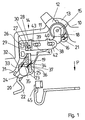
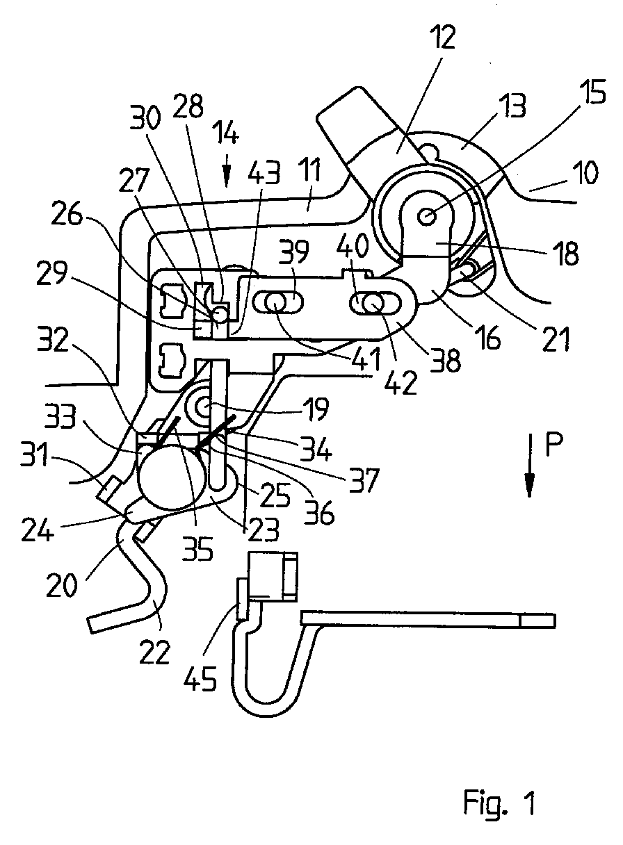
- Fig. 1 shows a circuit breaker 10 with a housing 11, the upper housing part is removed so that an insight into the circuit breaker is granted is.
- the circuit breaker 10 has a switch toggle 12 which emerges from an opening 13 of the circuit breaker 10 protrudes and in the area of the front wall 14 by one Axis of rotation 15 is pivotally mounted.
- the axis of rotation 15 is between two plates 16 stored, which have an approximately L-shaped shape, the longer leg about runs parallel to the front wall 14, whereas the short, perpendicular to it Leg 18 carries the pivot axis 15.
- the axis of rotation is between the two plates 16 19 of a movable contact lever 20 mounted, which is designed as a double arm lever is, one arm is coupled to a drive bracket 21 which on the Switch toggle 12 is articulated, whereas the other arm is a movable contact piece 22 carries, which cooperates with a fixed contact piece 45.
- a holding part 23 is rotatably mounted on the contact lever 20 and has a first nose 24 and has a second nose 25, the first nose approximately to the movable contact piece 22 protrudes, while on the second nose 25 serves as a release element 26 Is hinged, which rests with a leg 27 against a step 28, which is provided in one of the boards 16.
- To form the level 28 is in one board 16 has an approximately L-shaped recess 29, one leg of which Gradation 28 and the other leg 30 form a pocket, which is further below to be explained.
- a first stop 31 on the movable contact lever 20 There is a first stop 31 on the movable contact lever 20.
- a second stop Stop 32 is formed on the upper board 16, the first stop 31 with the nose 24 and the second stop 32 with an approximately perpendicular to the connecting line of the two lugs 24 and 25 extending third lug 33 cooperates.
- a return spring 34 is arranged around the holding part or element 23 one leg 35 bears against the stop 32 and the other leg 36 itself is supported on a shoulder 37 on the bracket 26 so that the bracket under the force of the spring 34 is pressed continuously in the direction of arrow P, whereby the holding element 23 continuously is applied clockwise.
- a slider 38 on the circuit board 16 is displaceable perpendicular to the extension of the bracket 26 integrally formed, which has two elongated holes 39 and 40, in which to guide the projections 41, 42 arranged on the board 16 engage.
- On the slide 38 is one of Slider formed from the protruding paragraph or step 43, the engages over the bracket 26.
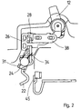
- Fig. 1 shows the circuit breaker in the off position. If the circuit breaker is to be switched on, then the switching knob 12 is clockwise pivoted, whereby the drive bracket 21 between the switching toggle 12 and the movable contact lever pivots this counterclockwise, so that the movable contact piece 22 moves towards the fixed contact piece 45. During this switch-on movement, the nose 31 of the movable contact lever lies down against the nose 24 and since the bracket 26 is supported against the step 28, the movable contact piece initially remains in the position shown in FIG. 2 stand in which the distance of the movable contact piece 22 to the fixed Contact piece 45 is reduced. The slide 38 also remains at rest.
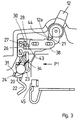
- the switching knob lays down with its drive bracket 21 leading extension 12a against a projection 44 on the slide 38, see Fig. 3 and with further pivoting of the shift knob 12, the extension 12 presses Switch toggle 12 against the projection 44 and moves the slider 38 in the direction of the arrow P1, so that this over the gradation 43 the bracket 26 to the left against Pivoted clockwise so that the leg 27 is released from the step 28 and can wander into the pocket 30.
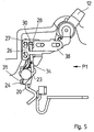
- the holding element 23 is released and can twist counter-clockwise, making it also movable Contact lever 20 allows the final switch-on movement in which the movable Contact piece 22 comes into contact with the fixed contact piece 45, see Fig. 5.
- This latter movement, in which the web 27 snaps into the pocket 30, is a quick movement and is (not shown) so that ultimately the switch-on movement from the position according to Fig. 4 in the position shown in FIG. 5 always runs at the same speed.
Landscapes
- Breakers (AREA)
- Switch Cases, Indication, And Locking (AREA)
Abstract
Es wird ein Schaltwerk für ein elektrisches Schaltgerät, insbesondere für einen Leitungsschutzschalter
beschrieben, der einen Schaltknebel (12) aufweist, der über ein
Schaltschloß ein bewegliches Kontaktstück (22) in Einschaltstellung bringt, wobei bei
der Einschaltbewegung eine Totpunktlage des Schaltschlosses überquert wird. Das
Schaltwerk besitzt eine erste Verklinkungsstelle, die das Schaltschloß in der Einschaltstellung
hält, und die von einem thermischen Auslöser geöffnet wird. Zur Erzielung einer
bestimmten Einschaltgeschwindigkeit zumindest im letzten Abschnitt der Einschaltbewegung
ist eine zweite Verklinkungsstelle (27, 28) vorgesehen, die eine ortsfeste Anlagestelle
(28) für einen mit dem beweglichen Kontaktstück (22) gekuppelten Bügel (26)
aufweist. Mit dem Schaltknebel (12) ein als Schieber ausgebildetes Auslöseelement
(38) gekuppelt, daß die zweite Verklinkungsstelle (28, 27) entriegelt, so daß sich das
bewegliche Kontaktstück (22) beschleunigt in Einschaltstellung bewegen kann.
Description
Die Erfindung betrifft ein Schaltwerk gemäß dem Oberbegriff des Anspruches 1.The invention relates to a switching mechanism according to the preamble of claim 1.
Ein derartiges Schaltgerät ist in dem Leitungsschutzschalter S 2 der Firma ABB Stotz-Kontakt GmbH, Heidelberg, eingebaut und damit bekannt. Dieses Schaltwerk besitzt einen Schaltknebel, der über ein zwischen zwei Platinen befindliches Schaltschloß ein bewegliches Kontaktstück bleibend aus der Ausschaltstellung in Einschaltstellung und umgekehrt bringt, wobei bei der Einschaltbewegung eine Totpunktlage des Schaltschlosses überquert wird. Dabei ist eine erste Verklinkungsstelle vorhanden, die das Schaltschloß in der Einschaltstellung hält und die von einem thermischen und/oder elektromagnetischen Auslöser entklinkt wird, so daß das Schaltschloß unter dem Einfluß einer Feder seine Totpunkt wieder überschreitet und in Ausschaltstellung geht.Such a switching device is in the circuit breaker S 2 from ABB Stotz-Kontakt GmbH, Heidelberg, installed and therefore known. This rear derailleur has a switch toggle, which is via a switch lock located between two circuit boards moving contact piece remaining in the off position in the on position and vice versa, with a dead center position of the key switch during the switch-on movement is crossed. There is a first latching point that the Switch lock holds in the on position and that of a thermal and / or electromagnetic release is released, so that the switch lock under the influence a spring exceeds its dead center and goes into the off position.
Bei diesem Schaltschloß bzw. Schaltwerk verläuft die Einschaltbewegung so, daß der bewegliche Schaltknebel verschwenkt wird; dadurch wird über einen damit verbundenen Hebel der Kontakthebel, der das bewegliche Kontaktstück trägt, angetrieben; diese Einschaltbewegung des beweglichen Kontaktstückes verläuft entsprechend der Geschwindigkeit, mit der der Schaltknebel verschwenkt wird. In this switch lock or switching mechanism, the switch-on movement runs so that the movable switching knob is pivoted; this is about an associated Lever the contact lever, which carries the movable contact piece, driven; this Switch-on movement of the movable contact piece runs according to the speed, with which the shift knob is pivoted.
Aufgabe der Erfindung ist es, ein Schaltwerk der eingangs genannten Art zu schaffen, bei wobei die Einschaltgeschwindigkeit der Kontaktstelle unabhängig ist von der Einschaltgeschwindigkeit der Bedienperson.The object of the invention is to provide a switching mechanism of the type mentioned in the introduction, where the switch-on speed of the contact point is independent of the switch-on speed the operator.
Diese Aufgabe wird erfindungsgemäß durch die Merkmale des Anspruches 1 gelöst.This object is achieved by the features of claim 1.
Erfindungsgemäß also ist eine zweite Verklinkungsstelle vorgesehen, die eine ortsfeste Anlagestelle für einen mit dem beweglichen Kontaktstück gekuppelten Hebel aufweist, und mit dem Schaltknebel ist erfindungsgemäß ein Auslöseelement gekuppelt, das die zweite Verklinkungsstelle entriegelt, so daß sich das bewegliche Kontaktstück beschleunigt in Ausschaltstellung bewegt.According to the invention, therefore, a second latching point is provided, which is a fixed one Has contact point for a lever coupled to the movable contact piece, and according to the invention a trigger element is coupled to the switching knob, which unlocked second latching point, so that the movable contact piece accelerates moved to the off position.
Dadurch wird die Einschaltbewegung immer mit der gleichen Geschwindigkeit ablaufen, so daß Verschweißungsvorgänge, wie sie bei zu langsamen Einschalten vorkommen können, vermieden werden. Bei mehrpoligen Ausführungen wird eine gleichzeitige Kontaktberührung erreicht. Wenn ein Pol ein Lullleiter (NA) zugeordnet ist, ist eine Vor- bzw. Nacheilung für das bewegliche Kontaktstück im NA-Pol nicht mehr erforderlich.This means that the switch-on movement will always run at the same speed, so that welding processes, such as occur when switching on too slowly can be avoided. With multi-pole versions, a simultaneous Contact reached. If a pole is assigned to a neutral conductor (NA), a lead or Tracking for the movable contact piece in the NA pole is no longer required.
Gemäß einer weiteren vorteilhaften Ausgestaltung der Erfindung kann bei verklinkter zweiter Verklinkungsstelle das Auslöseelement und damit das bewegliche Kontaktstück in einer Zwischenstellung festgehalten sein, aus der es erst bei Entklinkung der zweiten Verklinkungsstelle in die endgültige Einschaltstellung gelangt.According to a further advantageous embodiment of the invention, with the latched second latching point, the trigger element and thus the movable contact piece be held in an intermediate position, from which it is not released until the second Locking point reaches the final switch-on position.
Gemäß einer vorteilhaften Ausgestaltung der Erfindung ist ein Schieber vorgesehen, der mit dem Schaltknebel zur Entklinkung der zweiten Verklinkungsstelle gekuppelt ist, wobei der Schieber erst bei einer bestimmten Stellung, Zwischenstellung, des Schaltknebels mit diesem in Eingriff kommt und die zweite Verklinkungsstelle öffnet.According to an advantageous embodiment of the invention, a slide is provided, which is coupled to the switch to unlatch the second latch, the slide only at a certain position, intermediate position, of the shift knob engages with this and opens the second latching point.
Wenn ein Leitungsschutzschalter vorgesehen ist, der einen schwenkbaren Kontakthebei aufweist, an dem das bewegliche Kontaktstück befestigt ist, dann kann in der Drehachse des Kontakthebels ein Halteteil drehbar gelagert sein, das mit dem Auslöseelement der zweiten Verklinkungsstelle gekuppelt ist und von diesem in der bestimmten Zwischenstellung festgehalten ist. Der Kontakthebel ist dann in dieser bestimmten Zwischenstellung von dem Halteteil festgehalten.If a circuit breaker is provided which has a pivotable contact has, on which the movable contact piece is attached, then in the axis of rotation of the contact lever, a holding part can be rotatably mounted, which with the trigger element the second latching point is coupled and from this in the specific Intermediate position is recorded. The contact lever is then in this particular intermediate position held by the holding part.
Damit die Bewegung des Auslöseelementes in die verklinkte Stellung sichergestellt ist, kann zwischen dem Halteteil und dem Auslöseelement eine Rückstellfeder für das Auslöseelement angeordnet sein, die das Auslöseelement dauernd in Verklinkungsrichtung beaufschlagt. Gemäß einer vorteilhaften Ausführungsform ist die Rückstellfeder in zweckmäßiger Weise als zweiarme Schraubenfeder ausgebildet, deren einer Arm gegen das Auslöseelement und der anderer Arm gegen eine Widerlagernase am Kontakthebel anliegt.So that the movement of the release element into the latched position is ensured, can between the holding part and the trigger element, a return spring for Trigger element can be arranged, the trigger element permanently in the latching direction acted upon. According to an advantageous embodiment, the return spring Conveniently designed as a two-arm coil spring, one arm against the release element and the other arm against an abutment nose on the contact lever is present.
Anhand der Zeichnung, in der ein Ausführungsbeispiel der Erfindung dargestellt ist, sollen die Erfindung sowie weitere vorteilhafte Ausgestaltungen und Verbesserungen der Erfindung näher erläutert und beschrieben werden.Using the drawing, in which an embodiment of the invention is shown, the invention and further advantageous refinements and improvements the invention are explained and described in more detail.
Es zeigen:
- Fig. 1 bis 5
- einen Teil eines Leitungsschutzschalters mit Kontaktstelle, Schaltschloß und Schaltknebel, in unterschiedlichen Schaltstellungen, wobei die Fig. 1 die Einschaltstellung und die Fig. 5 die Ausschaltstellung zeigen, wogegen die Fig. 2 bis 4 Zwischenstellungen darstellen.
- 1 to 5
- a part of a circuit breaker with contact point, switch lock and switch toggle, in different switch positions, with FIG. 1 showing the switch-on position and FIG. 5 the switch-off position, whereas FIGS. 2 to 4 show intermediate positions.
Die Fig. 1 zeigt einen Leitungsschutzschalter 10 mit einem Gehäuse 11, wobei das Gehäuseoberteil
abgenommen ist, so daß ein Einblick in den Leitungsschutzschalter gewährt
ist.Fig. 1 shows a
Der Leitungsschutzschalter 10 besitzt einen Schaltknebel 12, der aus einer Öffnung 13
des Leitungsschutzschalters 10 herausragt und im Bereich der Frontwand 14 um eine
Drehachse 15 schwenkbar gelagert ist. Die Drehachse 15 ist zwischen zwei Platinen 16
gelagert, die eine etwa L-förmige Form aufweisen, wobei der längere Schenkel etwa
parallel zur Frontwand 14 verläuft, wogegen der kurze, senkrecht dazu verlaufende
Schenkel 18 die Schwenkachse 15 trägt. Zwischen den beiden Platinen 16 ist die Drehachse
19 eines beweglichen Kontakthebels 20 gelagert, der als Doppelarmhebel ausgebildet
ist, dessen einer Arm mit einem Antriebsbügel 21 gekoppelt ist, der an dem
Schaltknebel 12 angelenkt ist, wogegen der andere Arm ein bewegliches Kontaktstück
22 trägt, welches mit einem festen Kontaktstück 45 zusammenwirkt.The
Am Kontakthebel 20 ist ein Halteteil 23 drehbar gelagert, das eine erste Nase 24 und
eine zweite Nase 25 aufweist, wobei die erste Nase etwa zum beweglichen Kontaktstück
22 vorspringt, wogegen an der zweiten Nase 25 ein als Auslöseelement 26 dienender
Bügel angelenkt ist, der mit einem Schenkel 27 gegen eine Stufung 28 anliegt,
die in eine der Platinen 16 vorgesehen ist. Zur Bildung der Stufung 28 befindet sich in
der einen Platine 16 eine etwa L-förmige Ausnehmung 29, deren einer Schenkel die
Stufung 28 und deren anderer Schenkel 30 eine Tasche bilden, die weiter unten näher
erläutert werden soll.A
An dem beweglichen Kontakthebel 20 befindet sich ein erster Anschlag 31. Ein zweiter
Anschlag 32 ist an der oberen Platine 16 angeformt, wobei der erste Anschlag 31 mit
der Nase 24 und der zweite Anschlag 32 mit einer etwa senkrecht zur Verbindungslinie
der beiden Nasen 24 und 25 verlaufenden dritten Nase 33 zusammenwirkt.There is a
Um das Halteteil oder -element 23 herum ist eine Rückstellfeder 34 angeordnet, deren
einer Schenkel 35 gegen den Anschlag 32 anliegt und deren anderer Schenkel 36 sich
an einen Absatz 37 an dem Bügel 26 abstützt, so daß der Bügel unter der Kraft der Feder
34 dauernd in Pfeilrichtung P gedrückt wird, wodurch das Halteelement 23 dauernd
in Uhrzeigersinn beaufschlagt ist.A
Senkrecht zu der Ersteckung des Bügels 26 ist ein Schieber 38 an der Platine 16 verschieblich
angeformt, der zwei Langlöcher 39 und 40 aufweist, in die zur Führung an
der Platine 16 angeordnete Vorsprünge 41, 42 eingreifen. Am Schieber 38 ist eine vom
Schieber aus zum Betrachter hin vorspringender Absatz oder Stufung 43 angeformt, der
den Bügel 26 übergreift.A
Die Fig. 1 zeigt den Leitungsschutzschalter in Ausschaltstellung. Wenn der Leitungsschutzschalter
eingeschaltet werden soll, dann wird der Schaltknebel 12 in Uhrzeigersinn
verschwenkt, wodurch der Antriebsbügel 21 zwischen dem Schaltknebel 12 und
dem beweglichen Kontakthebel diesen entgegen dem Uhrzeigersinn verschwenkt, so
daß das bewegliche Kontaktstück 22 sich auf das feststehende Kontaktstück 45 zubewegt.
Während dieser Einschaltbewegung legt sich die Nase 31 des beweglichen Kontakthebels
gegen die Nase 24 an und da sich der Bügel 26 gegen die Stufung 28 abstützt,
bleibt das bewegliche Kontaktstück zunächst in der in Fig. 2 dargestellten Lage
stehen, in der der Abstand des beweglichen Kontaktstückes 22 zum feststehenden
Kontaktstück 45 reduziert ist. Der Schieber 38 verbleibt ebenfalls in Ruhe.Fig. 1 shows the circuit breaker in the off position. If the circuit breaker
is to be switched on, then the
In der Schaltstellung gemäß Fig. 3 legt sich der Schaltknebel mit seinem den Antriebsbügel
21 führenden Fortsatz 12a gegen einen Vorsprung 44 am Schieber 38 an, siehe
Fig. 3 und bei weiterer Verschwenkung des Schaltknebels 12 drückt der Fortsatz 12 am
Schaltknebel 12 gegen den Vorsprung 44 und verschiebt den Schieber 38 in Pfeilrichtung
P1, so daß dieser über die Stufung 43 den Bügel 26 nach links entgegen dem
Uhrzeigersinn verschwenkt, so daß der Schenkel 27 von der Stufung 28 freikommt und
in die Tasche 30 hineinwandern kann. Dadurch wird das Halteelement 23 freigegeben
und kann sich entgegen dem Uhrzeigersinn verdrehen, wodurch es auch dem beweglichen
Kontakthebel 20 die endgültige Einschaltbewegung gestattet, in dem das bewegliche
Kontaktstück 22 mit dem feststehenden Kontaktstück 45 in Berührung kommt,
siehe Fig. 5. Diese letztere Bewegung, bei der der Steg 27 in die Tasche 30 einschnappt,
ist eine schnelle Bewegung und wird durch die Energiespeicherfeder (nicht
gezeigt) bestimmt, so daß schlußendlich die Einschaltbewegung aus der Stellung gemäß
Fig. 4 in die Stellung gemäß Fig. 5 immer mit der gleichen Geschwindigkeit abläuft.In the switching position according to FIG. 3, the switching knob lays down with its
Wenn das Schaltgerät ausgeschaltet wird, wenn sich also der Kontakthebel 20 im Uhrzeigersinn
verschwenkt, dann zieht die Feder 34 den Bügel 26 in Pfeilrichtung P, so
daß der Steg 27 wieder hinter die Stufung 28 gelangt.When the switching device is switched off, that is, when the
Claims (6)
Applications Claiming Priority (2)
| Application Number | Priority Date | Filing Date | Title |
|---|---|---|---|
| DE19933110 | 1999-07-15 | ||
| DE19933110A DE19933110A1 (en) | 1999-07-15 | 1999-07-15 | Switchgear for an electrical switching device, in particular for a circuit breaker |
Publications (2)
| Publication Number | Publication Date |
|---|---|
| EP1069583A2 true EP1069583A2 (en) | 2001-01-17 |
| EP1069583A3 EP1069583A3 (en) | 2003-03-12 |
Family
ID=7914847
Family Applications (1)
| Application Number | Title | Priority Date | Filing Date |
|---|---|---|---|
| EP00113129A Withdrawn EP1069583A3 (en) | 1999-07-15 | 2000-06-29 | Switch mechanism for an electrical switchgear particularly for a circuit breaker |
Country Status (4)
| Country | Link |
|---|---|
| EP (1) | EP1069583A3 (en) |
| DE (1) | DE19933110A1 (en) |
| HU (1) | HUP0002636A2 (en) |
| PL (1) | PL341470A1 (en) |
Cited By (3)
| Publication number | Priority date | Publication date | Assignee | Title |
|---|---|---|---|---|
| DE10337661A1 (en) * | 2003-08-16 | 2005-03-10 | Abb Patent Gmbh | Circuit breaker, has pawl lever with catch which releases contact lever to trip switch to latching point |
| CN109243882A (en) * | 2018-09-26 | 2019-01-18 | 天佑电器(苏州)有限公司 | switch box device and power tool |
| CN113963966A (en) * | 2020-07-20 | 2022-01-21 | 上海良信电器股份有限公司 | Separating brake switch and remote circuit breaker |
Families Citing this family (1)
| Publication number | Priority date | Publication date | Assignee | Title |
|---|---|---|---|---|
| DE102005029059A1 (en) * | 2005-06-23 | 2006-12-28 | Abb Patent Gmbh | Switchgear, circuit breaker and the like |
Family Cites Families (5)
| Publication number | Priority date | Publication date | Assignee | Title |
|---|---|---|---|---|
| FR2628261B1 (en) * | 1988-03-02 | 1991-04-19 | Legrand Sa | CIRCUIT BREAKER WITH DEAD POINT MECHANISM |
| EP0338930A1 (en) * | 1988-04-22 | 1989-10-25 | Hager Electro S.A. | Circuit breakers or differential circuit breakers |
| DE4016364A1 (en) * | 1989-06-30 | 1991-01-03 | Siemens Ag | CIRCUIT BREAKER WITH TURN ON |
| AT404769B (en) * | 1993-01-21 | 1999-02-25 | Felten & Guilleaume Ag Oester | CIRCUIT BREAKER |
| DE19735415A1 (en) * | 1997-08-14 | 1999-02-18 | Siemens Ag | Switching mechanism for a circuit breaker |
-
1999
- 1999-07-15 DE DE19933110A patent/DE19933110A1/en not_active Withdrawn
-
2000
- 2000-06-29 EP EP00113129A patent/EP1069583A3/en not_active Withdrawn
- 2000-07-14 HU HU0002636A patent/HUP0002636A2/en unknown
- 2000-07-14 PL PL00341470A patent/PL341470A1/en unknown
Cited By (5)
| Publication number | Priority date | Publication date | Assignee | Title |
|---|---|---|---|---|
| DE10337661A1 (en) * | 2003-08-16 | 2005-03-10 | Abb Patent Gmbh | Circuit breaker, has pawl lever with catch which releases contact lever to trip switch to latching point |
| CN109243882A (en) * | 2018-09-26 | 2019-01-18 | 天佑电器(苏州)有限公司 | switch box device and power tool |
| CN109243882B (en) * | 2018-09-26 | 2023-11-21 | 天佑电器(苏州)有限公司 | Switch box device and power tool |
| CN113963966A (en) * | 2020-07-20 | 2022-01-21 | 上海良信电器股份有限公司 | Separating brake switch and remote circuit breaker |
| WO2022017075A1 (en) * | 2020-07-20 | 2022-01-27 | 华为数字能源技术有限公司 | Opening switch and remote circuit breaker |
Also Published As
| Publication number | Publication date |
|---|---|
| EP1069583A3 (en) | 2003-03-12 |
| HU0002636D0 (en) | 2000-09-28 |
| PL341470A1 (en) | 2001-01-29 |
| DE19933110A1 (en) | 2001-01-18 |
| HUP0002636A2 (en) | 2001-03-28 |
Similar Documents
| Publication | Publication Date | Title |
|---|---|---|
| DE69312154T2 (en) | Mechanical interlocking device of two switches with molded plastic housing | |
| EP2140521A1 (en) | Installation switchgear having a spring-loaded terminal arrangement | |
| EP2597669B1 (en) | Switching mechanism for an electric switching device and electrical switching apparatus | |
| DE2835354C2 (en) | Snap-action circuit breaker | |
| DE19619452C2 (en) | Slide-in device for a control panel for an electrical medium-voltage or low-voltage switchgear | |
| DE60029688T2 (en) | AUXILIARY MONITOR MODULE FOR AN ELECTRIC SWITCH WITH RELEASE | |
| DE10216439B4 (en) | auxiliary switch | |
| DE69218025T2 (en) | Electromechanical switching device with frontal additional component | |
| EP0718859A1 (en) | Device for the switching of an electric motor, in particular for braking an electric power tool | |
| DE3516217A1 (en) | CIRCUIT BREAKER | |
| DE2722279C3 (en) | Fuse switch | |
| DE102004055564B4 (en) | Electrical installation switching device | |
| DE4016364A1 (en) | CIRCUIT BREAKER WITH TURN ON | |
| EP1069583A2 (en) | Switch mechanism for an electrical switchgear particularly for a circuit breaker | |
| DE10322654B4 (en) | switchgear | |
| DE19519999C2 (en) | Arrangement to block or release the operation of a circuit breaker | |
| DE69207942T2 (en) | Electromechanical switch with additional reversing unit | |
| DE2705330C2 (en) | Electrical switch, in particular motor protection switch | |
| EP0145946B1 (en) | Line-protecting cut-out | |
| EP1709660B1 (en) | Electromechanical switch | |
| EP0565008B1 (en) | Test button device for an earth fault circuit breaker or a differential current circuit breaker | |
| DE102011018647B4 (en) | Electrical installation switching device | |
| EP1709659B1 (en) | Electromechanical switch | |
| EP1659604B1 (en) | Switchgear for an electric installation | |
| DE2505452A1 (en) | Compact electrical switch - has switch-arm and slotted linkage plate with common fixed pivot-point |
Legal Events
| Date | Code | Title | Description |
|---|---|---|---|
| PUAI | Public reference made under article 153(3) epc to a published international application that has entered the european phase |
Free format text: ORIGINAL CODE: 0009012 |
|
| AK | Designated contracting states |
Kind code of ref document: A2 Designated state(s): AT BE CH CY DE DK ES FI FR GB GR IE IT LI LU MC NL PT SE |
|
| AX | Request for extension of the european patent |
Free format text: AL;LT;LV;MK;RO;SI PAYMENT 20000705 |
|
| PUAL | Search report despatched |
Free format text: ORIGINAL CODE: 0009013 |
|
| AK | Designated contracting states |
Kind code of ref document: A3 Designated state(s): AT BE CH CY DE DK ES FI FR GB GR IE IT LI LU MC NL PT SE Designated state(s): AT BE CH CY DE DK ES FI FR GB GR IE IT LI LU MC NL PT SE |
|
| AX | Request for extension of the european patent |
Extension state: AL LT LV MK RO SI |
|
| STAA | Information on the status of an ep patent application or granted ep patent |
Free format text: STATUS: THE APPLICATION IS DEEMED TO BE WITHDRAWN |
|
| 18D | Application deemed to be withdrawn |
Effective date: 20021231 |