EP1069583A3 - Switch mechanism for an electrical switchgear particularly for a circuit breaker - Google Patents
Switch mechanism for an electrical switchgear particularly for a circuit breaker Download PDFInfo
- Publication number
- EP1069583A3 EP1069583A3 EP00113129A EP00113129A EP1069583A3 EP 1069583 A3 EP1069583 A3 EP 1069583A3 EP 00113129 A EP00113129 A EP 00113129A EP 00113129 A EP00113129 A EP 00113129A EP 1069583 A3 EP1069583 A3 EP 1069583A3
- Authority
- EP
- European Patent Office
- Prior art keywords
- switch
- circuit breaker
- movable contact
- contact piece
- switching
- Prior art date
- Legal status (The legal status is an assumption and is not a legal conclusion. Google has not performed a legal analysis and makes no representation as to the accuracy of the status listed.)
- Withdrawn
Links
Classifications
-
- H—ELECTRICITY
- H01—ELECTRIC ELEMENTS
- H01H—ELECTRIC SWITCHES; RELAYS; SELECTORS; EMERGENCY PROTECTIVE DEVICES
- H01H71/00—Details of the protective switches or relays covered by groups H01H73/00 - H01H83/00
- H01H71/10—Operating or release mechanisms
- H01H71/50—Manual reset mechanisms which may be also used for manual release
- H01H71/52—Manual reset mechanisms which may be also used for manual release actuated by lever
-
- H—ELECTRICITY
- H01—ELECTRIC ELEMENTS
- H01H—ELECTRIC SWITCHES; RELAYS; SELECTORS; EMERGENCY PROTECTIVE DEVICES
- H01H2300/00—Orthogonal indexing scheme relating to electric switches, relays, selectors or emergency protective devices covered by H01H
- H01H2300/046—Orthogonal indexing scheme relating to electric switches, relays, selectors or emergency protective devices covered by H01H using snap closing mechanisms
- H01H2300/048—Snap closing by latched movable contact, wherein the movable contact is held in a minimal distance from the fixed contact during first phase of closing sequence in which a closing spring is charged
Landscapes
- Switch Cases, Indication, And Locking (AREA)
- Breakers (AREA)
Abstract
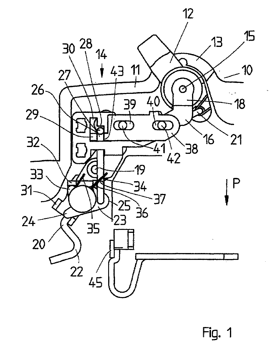
Es wird ein Schaltwerk für ein elektrisches Schaltgerät, insbesondere für einen Leitungsschutzschalter
beschrieben, der einen Schaltknebel (12) aufweist, der über ein
Schaltschloß ein bewegliches Kontaktstück (22) in Einschaltstellung bringt, wobei bei
der Einschaltbewegung eine Totpunktlage des Schaltschlosses überquert wird. Das
Schaltwerk besitzt eine erste Verklinkungsstelle, die das Schaltschloß in der Einschaltstellung
hält, und die von einem thermischen Auslöser geöffnet wird. Zur Erzielung einer
bestimmten Einschaltgeschwindigkeit zumindest im letzten Abschnitt der Einschaltbewegung
ist eine zweite Verklinkungsstelle (27, 28) vorgesehen, die eine ortsfeste Anlagestelle
(28) für einen mit dem beweglichen Kontaktstück (22) gekuppelten Bügel (26)
aufweist. Mit dem Schaltknebel (12) ein als Schieber ausgebildetes Auslöseelement
(38) gekuppelt, daß die zweite Verklinkungsstelle (28, 27) entriegelt, so daß sich das
bewegliche Kontaktstück (22) beschleunigt in Einschaltstellung bewegen kann.
Applications Claiming Priority (2)
| Application Number | Priority Date | Filing Date | Title |
|---|---|---|---|
| DE19933110 | 1999-07-15 | ||
| DE19933110A DE19933110A1 (en) | 1999-07-15 | 1999-07-15 | Switchgear for an electrical switching device, in particular for a circuit breaker |
Publications (2)
| Publication Number | Publication Date |
|---|---|
| EP1069583A2 EP1069583A2 (en) | 2001-01-17 |
| EP1069583A3 true EP1069583A3 (en) | 2003-03-12 |
Family
ID=7914847
Family Applications (1)
| Application Number | Title | Priority Date | Filing Date |
|---|---|---|---|
| EP00113129A Withdrawn EP1069583A3 (en) | 1999-07-15 | 2000-06-29 | Switch mechanism for an electrical switchgear particularly for a circuit breaker |
Country Status (4)
| Country | Link |
|---|---|
| EP (1) | EP1069583A3 (en) |
| DE (1) | DE19933110A1 (en) |
| HU (1) | HUP0002636A2 (en) |
| PL (1) | PL341470A1 (en) |
Families Citing this family (4)
| Publication number | Priority date | Publication date | Assignee | Title |
|---|---|---|---|---|
| DE10337661A1 (en) * | 2003-08-16 | 2005-03-10 | Abb Patent Gmbh | Circuit breaker, has pawl lever with catch which releases contact lever to trip switch to latching point |
| DE102005029059A1 (en) * | 2005-06-23 | 2006-12-28 | Abb Patent Gmbh | Switchgear, circuit breaker and the like |
| CN109243882B (en) * | 2018-09-26 | 2023-11-21 | 天佑电器(苏州)有限公司 | Switch box device and power tool |
| CN113963966B (en) * | 2020-07-20 | 2022-09-06 | 上海良信电器股份有限公司 | Separating brake switch and remote circuit breaker |
Citations (4)
| Publication number | Priority date | Publication date | Assignee | Title |
|---|---|---|---|---|
| FR2628261A1 (en) * | 1988-03-02 | 1989-09-08 | Legrand Sa | Circuit breaker with quick-make switching action - moving contact is positioned by spring linkage, compressed against mid-point checks which causes movement when latter are overcome |
| EP0338930A1 (en) * | 1988-04-22 | 1989-10-25 | Hager Electro S.A. | Circuit breakers or differential circuit breakers |
| WO1994017545A1 (en) * | 1993-01-21 | 1994-08-04 | Felten & Guilleaume Austria Ag | Line safety switch |
| EP0897186A2 (en) * | 1997-08-14 | 1999-02-17 | Siemens Aktiengesellschaft | Switch mechanism for a circuit breaker |
Family Cites Families (1)
| Publication number | Priority date | Publication date | Assignee | Title |
|---|---|---|---|---|
| DE4016364A1 (en) * | 1989-06-30 | 1991-01-03 | Siemens Ag | CIRCUIT BREAKER WITH TURN ON |
-
1999
- 1999-07-15 DE DE19933110A patent/DE19933110A1/en not_active Withdrawn
-
2000
- 2000-06-29 EP EP00113129A patent/EP1069583A3/en not_active Withdrawn
- 2000-07-14 PL PL00341470A patent/PL341470A1/en unknown
- 2000-07-14 HU HU0002636A patent/HUP0002636A2/en unknown
Patent Citations (4)
| Publication number | Priority date | Publication date | Assignee | Title |
|---|---|---|---|---|
| FR2628261A1 (en) * | 1988-03-02 | 1989-09-08 | Legrand Sa | Circuit breaker with quick-make switching action - moving contact is positioned by spring linkage, compressed against mid-point checks which causes movement when latter are overcome |
| EP0338930A1 (en) * | 1988-04-22 | 1989-10-25 | Hager Electro S.A. | Circuit breakers or differential circuit breakers |
| WO1994017545A1 (en) * | 1993-01-21 | 1994-08-04 | Felten & Guilleaume Austria Ag | Line safety switch |
| EP0897186A2 (en) * | 1997-08-14 | 1999-02-17 | Siemens Aktiengesellschaft | Switch mechanism for a circuit breaker |
Also Published As
| Publication number | Publication date |
|---|---|
| HUP0002636A2 (en) | 2001-03-28 |
| HU0002636D0 (en) | 2000-09-28 |
| DE19933110A1 (en) | 2001-01-18 |
| EP1069583A2 (en) | 2001-01-17 |
| PL341470A1 (en) | 2001-01-29 |
Similar Documents
| Publication | Publication Date | Title |
|---|---|---|
| KR920001591A (en) | Electrical circuit breaker operation block | |
| EP0897186A3 (en) | Switch mechanism for a circuit breaker | |
| ATE22748T1 (en) | ELECTRICAL SWITCHING DEVICE, PARTICULARLY CONTACTOR. | |
| EP1069583A3 (en) | Switch mechanism for an electrical switchgear particularly for a circuit breaker | |
| DE68916815D1 (en) | Automatic switches, especially differential and circuit breakers. | |
| EP0884747A3 (en) | Switchgear for an electric installation | |
| EP1542254A3 (en) | Slot motor including legs engaging openings of circuit breaker housing and electrical switching apparatus employing the same | |
| GB1264603A (en) | ||
| US3796844A (en) | Multiple circuit control switch assembly with momentary action interlocking means | |
| EP0398461A3 (en) | Circuit breaker with an actuating and a locking device for a moving contact | |
| ATE173354T1 (en) | LOW VOLTAGE CIRCUIT BREAKER WITH RELATIVE AUXILIARY SWITCH | |
| ATE424619T1 (en) | SWITCHGEAR FOR AN ELECTRICAL INSTALLATION SWITCHGEAR | |
| EP0820084A3 (en) | Operating device for circuit breakers | |
| EP0956575B1 (en) | Power breaker switching an electric circuit | |
| ATE68909T1 (en) | OVERCURRENT PROTECTION SWITCH. | |
| DK0693220T3 (en) | Electromagnetic circuit breaker for electrical circuit breakers | |
| WO2003041100A3 (en) | Electric switch | |
| EP0884927A3 (en) | Switching element for electrical appliances, such as electrical heaters | |
| US3591745A (en) | Manually operated toggle acting switch having a job function lever | |
| PL316654A1 (en) | Actuating device for vacuum-type power disconnector switch especially three-pole one | |
| ATE73263T1 (en) | PUSH-BUTTON ACTUATED OVERCURRENT PROTECTION SWITCH. | |
| DE893835C (en) | Manually operated motor protection switch | |
| ATE138760T1 (en) | SWITCHING DEVICE, IN PARTICULAR CIRCUIT BREAKERS | |
| SU736198A1 (en) | Multi-row change-over switch with automatic release | |
| KR970071879A (en) | Actuators of electrical appliances such as breakers and motors |
Legal Events
| Date | Code | Title | Description |
|---|---|---|---|
| PUAI | Public reference made under article 153(3) epc to a published international application that has entered the european phase |
Free format text: ORIGINAL CODE: 0009012 |
|
| AK | Designated contracting states |
Kind code of ref document: A2 Designated state(s): AT BE CH CY DE DK ES FI FR GB GR IE IT LI LU MC NL PT SE |
|
| AX | Request for extension of the european patent |
Free format text: AL;LT;LV;MK;RO;SI PAYMENT 20000705 |
|
| PUAL | Search report despatched |
Free format text: ORIGINAL CODE: 0009013 |
|
| AK | Designated contracting states |
Kind code of ref document: A3 Designated state(s): AT BE CH CY DE DK ES FI FR GB GR IE IT LI LU MC NL PT SE Designated state(s): AT BE CH CY DE DK ES FI FR GB GR IE IT LI LU MC NL PT SE |
|
| AX | Request for extension of the european patent |
Extension state: AL LT LV MK RO SI |
|
| STAA | Information on the status of an ep patent application or granted ep patent |
Free format text: STATUS: THE APPLICATION IS DEEMED TO BE WITHDRAWN |
|
| 18D | Application deemed to be withdrawn |
Effective date: 20021231 |