EP1069561A1 - Dispositif de commande de vitesse de disque - Google Patents
Dispositif de commande de vitesse de disque Download PDFInfo
- Publication number
- EP1069561A1 EP1069561A1 EP00113990A EP00113990A EP1069561A1 EP 1069561 A1 EP1069561 A1 EP 1069561A1 EP 00113990 A EP00113990 A EP 00113990A EP 00113990 A EP00113990 A EP 00113990A EP 1069561 A1 EP1069561 A1 EP 1069561A1
- Authority
- EP
- European Patent Office
- Prior art keywords
- disc
- data
- rotation speed
- speed
- frequency
- Prior art date
- Legal status (The legal status is an assumption and is not a legal conclusion. Google has not performed a legal analysis and makes no representation as to the accuracy of the status listed.)
- Granted
Links
- 230000003287 optical effect Effects 0.000 claims description 4
- 238000000034 method Methods 0.000 claims description 3
- 230000001105 regulatory effect Effects 0.000 description 6
- 230000001133 acceleration Effects 0.000 description 2
- 239000000969 carrier Substances 0.000 description 1
- 230000002093 peripheral effect Effects 0.000 description 1
- 230000000704 physical effect Effects 0.000 description 1
Images
Classifications
-
- G—PHYSICS
- G11—INFORMATION STORAGE
- G11B—INFORMATION STORAGE BASED ON RELATIVE MOVEMENT BETWEEN RECORD CARRIER AND TRANSDUCER
- G11B19/00—Driving, starting, stopping record carriers not specifically of filamentary or web form, or of supports therefor; Control thereof; Control of operating function ; Driving both disc and head
- G11B19/20—Driving; Starting; Stopping; Control thereof
- G11B19/28—Speed controlling, regulating, or indicating
Definitions
- the invention relates to a playing and/or recording device for a disc shaped information carrier, and more precisely to a disc speed control device.
- a playing and/or recording device for a disc shaped carrier is known to adjust the disc rotation speed depending on the nature of the disc.
- two modes are used, namely Constant Angular Velocity and Constant Linear Velocity mode.
- a leading value output means In a start phase after the disc has been inserted in the CD-ROM player and is ready to be read, a leading value output means generates a determined start rotation speed value. This value is output to speed servo means which regulate disc actuating means such to rotate the disc at the start rotation speed.
- An instantaneous disc rotation speed may be obtained from a frequency signal which is generated by frequency generating means.
- the frequency generating means may for example be realized by a device which is directly measuring the rotations of a motor shaft in the disc actuating means.
- the speed servo means receive the frequency signal, compare the determined start rotation speed with the instantaneous disc rotation speed calculated from the frequency signal, and consequently regulate the disc actuating means such that the disc keeps rotating at the determined start rotation speed. Any other speed may now be adjusted by using the leading value output means.
- Disc players and/or recording devices typically comprise a pick up which may be moved relative to the rotating disc in order to be positioned for reading and/or recording data at a determined location of the disc.
- the pick up comprises optical means which receive light reflected by the disc and project it on light detecting means. This way an output of the light detecting means is indicative of data scanned by the reflected light.
- the data may for example be recorded along tracks.
- the tracks form circles or a spiral having a center substantially located at a center of the disc rotation.
- the disc In CLV mode the disc is rotated such that data being read and/or recorded using the pick-up appears to be passing by the pick-up at a constant speed. This means that the disc rotation speed is actually higher when the pick-up accesses data near the center of the disc than when it accessed data near a periphery of the disc. This is for example the case in audio Compact Disc players.
- the disc rotation speed must be adjusted depending on where on the disc the pick-up is to access data.
- an output of the pick-up i.e., an output of the light detecting means is processed using signal processing means and a data frequency signal showing at which frequency data is read by the pick-up is obtained.
- the data frequency signal is compared to a desired frequency corresponding to a determined linear velocity and a speed servo circuit regulates the disc actuating means in a known manner such that the disk rotations speed remains adapted to have a data frequency signal substantially equal to the desired frequency.
- a disc speed control device is for use in a player and/or recorder of a disc shaped information carrier to be recorded or recorded with data along data tracks, the data being read and/or recorded using a pick-up, and comprises frequency generating means for generating a frequency signal having a frequency representative of a rotation speed of the disc, disc actuating means for rotating the disc, leading value output means for generating a determined rotation speed value, speed servo means which receive the frequency signal and the determined rotation speed value, and which regulate the disc actuating means to the determined rotation speed value, signal processing means which process an output of the pick-up when the data is being read and deliver a data frequency signal, and speed processing means which receive and use the data frequency signal to compute the determined rotation speed value.
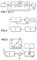
- Fig.1 shows a schematic representation of known disc actuating means 1 which are used to rotate a disc shaped data carrier (not shown).
- a frequency generating means 2 measures for example the rotations of a motor shaft (not shown) which rotates in the disc actuating means 1.
- the frequency generating means 2 thereby generate a frequency signal which has a frequency representative of a rotation speed of the disc, and transmit this to speed servo means 3.
- a leading value output means 4 generates a determined rotation speed value which is transmitted to the speed servo means 3.
- the determined rotation speed value corresponds to a desired rotation speed in CAV mode.
- the speed servo means 3 comprises a comparator means 5 which receives both the frequency signal and the determined rotation speed value, compares both inputs and delivers the result of the comparison to a regulating means 6.
- the regulating means 6 outputs a regulating signal to the disc actuating means 1 through an amplifier 7 such that a rotation of the disc shaped data carrier at the determined rotation speed value is obtained.
- the disc actuating means will accelerate or decelerate the disc rotation depending on respectively if the frequency signal indicates an instantaneous speed smaller or greater than the determined rotation speed value.
- a CAV mode operation is achieved because the disc rotating is regulated at a constant determined rotation speed.
- the determined rotation speed value is provided to the speed servo means 3 by speed processing means 8.
- a pick-up 9 is used to read data from the rotating disk shaped carrier (not shown) and delivers to a signal processing means 10 a signal representative of the data scanned from the disc.
- the signal processing means 10 allows to generate a data frequency signal which depends on the frequency at which data is scanned by the pick-up, i.e., on the linear velocity at which the disc passes by the pick-up 9.
- the speed processing means 8 receives the data frequency signal and computes the determined rotation speed value. In case a CLV mode is to be achieved, the determined rotation speed value will depend on the location of the disc at which the pick-up 9 reads the data.
- the speed servo means 3 then regulates the disc actuating means 1 to rotate the disc at the determined rotation speed value.
- To read includes reading data stored in the form of pits in the form of depressions or elevations, dark or bright areas, areas differing in other physical properties as for example magnetic properties, optical properties, electrical properties or geometric properties, like a differently wobbled track.
- data is also read during a recording process. For example during following the track prerecorded areas in the form of pits or wobble information are read and evaluated, even when recording is performed.
- the described example in fact acts as a system of two loops: an inner loop comprising the speed servo means 3, the disc actuating means 1 and the frequency generating means 2, and receiving a determined rotation speed value at its input.
- the second loop may be called outer loop or control loop and provides the determined rotation speed value to the input of the inner loop.
- the outer loop and more precisely the speed processing means 8 which is part of it, may typically provide processing of the data frequency signal for achieving CLV mode.
- the outer loop may also provide processing for one or many of the following situations:
- Fig. 3 shows a preferred embodiment of an outer loop.
- a data Phase Locked Loop 11 receives an output from the pick-up 9.
- the data PLL 11 comprises means for generating a voltage U depending on a frequency of the read data rate which is defined as a PLL frequency f.
- the data PLL 11 outputs the voltage U according to a voltage curve 12.
- the voltage curve 12 shows that PLL frequencies f-, f0 and f+ correspond to voltage U-, U0 and U+.
- the speed processing means 8 receives at its input the voltage output by the data PLL 11 and a reference voltage Uv ; the input voltages are compared and depending on the result the speed processing means 8 output a higher or smaller determined disc rotation value, such that the PLL frequency remains substantially at the frequency f0.
- a CLV mode may be achieved.
- the disc speed control device is particularly advantageous in that it may easily be used for various kinds of recording and/or playing modes. This is especially useful in multi-standard disc drives which need to adjust many different disc speeds to read or record data.
Landscapes
- Rotational Drive Of Disk (AREA)
Priority Applications (1)
| Application Number | Priority Date | Filing Date | Title |
|---|---|---|---|
| EP20000113990 EP1069561B1 (fr) | 1999-07-13 | 2000-07-01 | Dispositif de commande de vitesse de disque |
Applications Claiming Priority (3)
| Application Number | Priority Date | Filing Date | Title |
|---|---|---|---|
| EP99401755 | 1999-07-13 | ||
| EP99401755A EP1069562A1 (fr) | 1999-07-13 | 1999-07-13 | Dispositif de commande de vitesse de disque |
| EP20000113990 EP1069561B1 (fr) | 1999-07-13 | 2000-07-01 | Dispositif de commande de vitesse de disque |
Publications (2)
| Publication Number | Publication Date |
|---|---|
| EP1069561A1 true EP1069561A1 (fr) | 2001-01-17 |
| EP1069561B1 EP1069561B1 (fr) | 2006-10-04 |
Family
ID=26071109
Family Applications (1)
| Application Number | Title | Priority Date | Filing Date |
|---|---|---|---|
| EP20000113990 Expired - Lifetime EP1069561B1 (fr) | 1999-07-13 | 2000-07-01 | Dispositif de commande de vitesse de disque |
Country Status (1)
| Country | Link |
|---|---|
| EP (1) | EP1069561B1 (fr) |
Citations (3)
| Publication number | Priority date | Publication date | Assignee | Title |
|---|---|---|---|---|
| US5051976A (en) * | 1987-05-15 | 1991-09-24 | Pioneer Electronic Corporation | Disk recording and reproducing apparatus with speed compensation for CAV and CLV disks in accordance with signals recorded on the disks |
| JPH10106136A (ja) * | 1996-09-30 | 1998-04-24 | Sanyo Electric Co Ltd | 光ディスク用スピンドルモータのサーボ制御装置 |
| EP0878795A2 (fr) * | 1997-05-13 | 1998-11-18 | Matsushita Electric Industrial Co., Ltd. | Système de commande de moteur de broche pour tourne-disque |
-
2000
- 2000-07-01 EP EP20000113990 patent/EP1069561B1/fr not_active Expired - Lifetime
Patent Citations (3)
| Publication number | Priority date | Publication date | Assignee | Title |
|---|---|---|---|---|
| US5051976A (en) * | 1987-05-15 | 1991-09-24 | Pioneer Electronic Corporation | Disk recording and reproducing apparatus with speed compensation for CAV and CLV disks in accordance with signals recorded on the disks |
| JPH10106136A (ja) * | 1996-09-30 | 1998-04-24 | Sanyo Electric Co Ltd | 光ディスク用スピンドルモータのサーボ制御装置 |
| EP0878795A2 (fr) * | 1997-05-13 | 1998-11-18 | Matsushita Electric Industrial Co., Ltd. | Système de commande de moteur de broche pour tourne-disque |
Non-Patent Citations (1)
| Title |
|---|
| PATENT ABSTRACTS OF JAPAN vol. 1998, no. 09 31 July 1998 (1998-07-31) * |
Also Published As
| Publication number | Publication date |
|---|---|
| EP1069561B1 (fr) | 2006-10-04 |
Similar Documents
| Publication | Publication Date | Title |
|---|---|---|
| US6195322B1 (en) | Disk drive device and method of setting rotational speed thereof | |
| US5161142A (en) | Disk playing apparatus for playing CLV disks | |
| US5745460A (en) | Disk discriminating method and apparatus | |
| US6128261A (en) | Disk unit and rotating motor control apparatus for recordable optical disk unit | |
| EP0193961A2 (fr) | Procédé pour sélectionner des informations d'un appareil de reproduction à disques | |
| KR0176599B1 (ko) | 씨디-롬 드라이브의 구동방법 | |
| US6952386B1 (en) | Disc speed control device | |
| US5802026A (en) | Disk player for constant angular velocity reproduction of a disk | |
| EP1069561B1 (fr) | Dispositif de commande de vitesse de disque | |
| KR0162374B1 (ko) | 디스크 재생시 모터 제어장치 및 방법 | |
| KR19980042575A (ko) | 디스크 재생 장치 및 헤드 위치 계산 방법 | |
| JP2000311361A (ja) | 光ディスク装置のピックアップ制御装置 | |
| JP3801621B2 (ja) | アクセス時間の短縮方法 | |
| JP3673520B2 (ja) | 再生装置のアクセス時間短縮方法 | |
| US6633524B1 (en) | Method for controlling rotation of an optical disk during a zone change in a data read out operation | |
| US6917577B2 (en) | Method for determining position of optic pick-up head and device of the same | |
| KR0131416B1 (ko) | 광디스크 재생장치의 트랙점프 제어회로 및 방법 | |
| KR20010024928A (ko) | 디스크 장치 | |
| US20040156287A1 (en) | Method of accelerating a track-following process for an optical drive | |
| JPH1186430A (ja) | 光ディスク再生装置 | |
| JP3124220B2 (ja) | 光ディスク再生装置 | |
| JP3689990B2 (ja) | Pll回路 | |
| KR100624274B1 (ko) | 광 디스크 기록/재생 장치의 제어 방법 | |
| KR20010092257A (ko) | 디스크 장치 | |
| JP3649172B2 (ja) | ディスク記録装置 |
Legal Events
| Date | Code | Title | Description |
|---|---|---|---|
| PUAI | Public reference made under article 153(3) epc to a published international application that has entered the european phase |
Free format text: ORIGINAL CODE: 0009012 |
|
| AK | Designated contracting states |
Kind code of ref document: A1 Designated state(s): DE FR GB IT |
|
| AX | Request for extension of the european patent |
Free format text: AL;LT;LV;MK;RO;SI |
|
| 17P | Request for examination filed |
Effective date: 20010703 |
|
| AKX | Designation fees paid |
Free format text: DE FR GB IT |
|
| GRAP | Despatch of communication of intention to grant a patent |
Free format text: ORIGINAL CODE: EPIDOSNIGR1 |
|
| GRAS | Grant fee paid |
Free format text: ORIGINAL CODE: EPIDOSNIGR3 |
|
| GRAA | (expected) grant |
Free format text: ORIGINAL CODE: 0009210 |
|
| AK | Designated contracting states |
Kind code of ref document: B1 Designated state(s): DE FR GB IT |
|
| PG25 | Lapsed in a contracting state [announced via postgrant information from national office to epo] |
Ref country code: IT Free format text: LAPSE BECAUSE OF FAILURE TO SUBMIT A TRANSLATION OF THE DESCRIPTION OR TO PAY THE FEE WITHIN THE PRESCRIBED TIME-LIMIT;WARNING: LAPSES OF ITALIAN PATENTS WITH EFFECTIVE DATE BEFORE 2007 MAY HAVE OCCURRED AT ANY TIME BEFORE 2007. THE CORRECT EFFECTIVE DATE MAY BE DIFFERENT FROM THE ONE RECORDED. Effective date: 20061004 |
|
| REG | Reference to a national code |
Ref country code: GB Ref legal event code: FG4D |
|
| REF | Corresponds to: |
Ref document number: 60031046 Country of ref document: DE Date of ref document: 20061116 Kind code of ref document: P |
|
| ET | Fr: translation filed | ||
| PLBE | No opposition filed within time limit |
Free format text: ORIGINAL CODE: 0009261 |
|
| STAA | Information on the status of an ep patent application or granted ep patent |
Free format text: STATUS: NO OPPOSITION FILED WITHIN TIME LIMIT |
|
| 26N | No opposition filed |
Effective date: 20070705 |
|
| PGFP | Annual fee paid to national office [announced via postgrant information from national office to epo] |
Ref country code: FR Payment date: 20090722 Year of fee payment: 10 |
|
| PGFP | Annual fee paid to national office [announced via postgrant information from national office to epo] |
Ref country code: DE Payment date: 20090721 Year of fee payment: 10 Ref country code: GB Payment date: 20090629 Year of fee payment: 10 |
|
| GBPC | Gb: european patent ceased through non-payment of renewal fee |
Effective date: 20100701 |
|
| REG | Reference to a national code |
Ref country code: FR Ref legal event code: ST Effective date: 20110331 |
|
| PG25 | Lapsed in a contracting state [announced via postgrant information from national office to epo] |
Ref country code: DE Free format text: LAPSE BECAUSE OF NON-PAYMENT OF DUE FEES Effective date: 20110201 |
|
| REG | Reference to a national code |
Ref country code: DE Ref legal event code: R119 Ref document number: 60031046 Country of ref document: DE Effective date: 20110201 |
|
| PG25 | Lapsed in a contracting state [announced via postgrant information from national office to epo] |
Ref country code: FR Free format text: LAPSE BECAUSE OF NON-PAYMENT OF DUE FEES Effective date: 20100802 |
|
| PG25 | Lapsed in a contracting state [announced via postgrant information from national office to epo] |
Ref country code: GB Free format text: LAPSE BECAUSE OF NON-PAYMENT OF DUE FEES Effective date: 20100701 |